Note : Les descriptions sont présentées dans la langue officielle dans laquelle elles ont été soumises.
CA 02920542 2016-02-04
WO 2015/023922 PCT/US2014/051217
Catheter Connection and Stabilization Device and Methods of Using Same
Priority
[0001] This patent application claims priority from United States Provisional
Patent
Application number 61/866,686, filed August 16, 2013, entitled, "Catheter
Connection and
Stabilization Device and Methods of Using Same," and naming Luis Maseda, Todd
Chelak, Nick Dennis, and Ian Kimball as inventors, the disclosure of which is
incorporated
herein, in its entirety, by reference.
Technical Field
[0002] The present invention relates to devices for securing a catheter to a
patient,
and more particularly to devices that stabilize and secure catheters to a
patient and allow for
connection of a medical implement.
Background Art
[0003] In instances in which a patient will need regular administration of
fluid or
medications (or regular withdrawal of fluids/blood), catheters are often
inserted into the
patient and used to administer the fluids/medications. The catheter may remain
in the patient
for extended periods of time (several hours to several days). Additionally, an
extension tube
may be connected to the catheter to facilitate use of the catheter and
connection of a medical
implement (e.g., a syringe). To ensure that the catheter and/or extension tube
remain in place
and are not accidentally removed, some prior art systems secure the catheter
and/or extension
tube to the patient using tape or similar adhesive materials (e.g., a film
dressing).
[0004] Tapes and adhesive film dressings can be problematic in that they may
not
firmly secure the catheter in place. Additionally, in some instances, the
manner in which the
tape is applied and the positioning/location of the catheter and/or extension
tube may cause
the catheter and/or extension tube to be bent. This, in turn, increases the
risk of kinking
i
CA 02920542 2016-02-04
WO 2015/023922 PCT/US2014/051217
(which can reduce/stop flow through the catheter and/or extension tube) and
makes it more
difficult to connect the medical implement required to introduce the
fluid/medication.
Summary of the Embodiments
[0005] In a first embodiment of the invention there is provided a catheter
connection
and stabilization device that includes a medical valve, a male luer connector
for connection
to a catheter, and an adherent substrate (e.g., a dressing, tape, or similar
substrate having an
adhesive). The medical valve may have an open mode that permits fluid flow
through the
valve and a closed mode that prevents fluid through the valve. The medical
valve may also
include a housing having an inlet and an outlet. The dressing may have a first
and at least a
second film layer that at least partially define at least one fluid pathway.
The at least one
fluid pathway may extend through the dressing between at least two film layers
and fluidly
connect the outlet of the medical valve and the male luer connector.
Alternatively, the fluid
path may be formed by the first and second film layers overlaying a third film
layer
containing a void, the void being encapsulated by the first and second layers.
The dressing
may also include an adhesive layer located on an underside of the second film
layer that is
configured to secure the dressing to a patient.
[0006] In some embodiments, the medical valve may include a split septum
obstructing the inlet of the medical valve, and connection of a medical
implement to the inlet
of the medical valve may deform the split septum to transition the medical
valve from the
closed mode to the open mode. The stabilization device may also include a
docking pod
located between the male luer connector and the at least one fluid pathway.
The docking pod,
in turn, may include (1) a docking pod adhesive layer located at least
partially on the
underside of at least a portion of the docking pod for securing the docking
pod to the patient,
and (2) a pressure activated valve. Alternatively, the docking pod may be
mechanically
joined to the topside of the dressing with the docking pod adhesive then
located on the
underside of the dressing for securing the docking pod to the patient. The
pressure activated
valve may include a diaphragm with a slit through it. The slit may have a
cracking pressure
above which the slit opens to allow fluid flow through the pressure activated
valve. For
example, the backward cracking pressure may be greater than the venous
pressure of the vein
in which the catheter is inserted and may be greater than the forward cracking
pressure.
2
CA 02920542 2016-02-04
WO 2015/023922 PCT/US2014/051217
[0007] The at least one fluid pathway may have a first fluid volume when the
medical
implement is connected to the medical valve and a second fluid volume when the
medical
implement is disconnected from the medical valve. The first fluid volume may
be greater
than the second fluid volume. Additionally or alternatively, the first film
layer and/or the at
least second film layer may be formed with a channel that defines at least
part of the at least
one fluid pathway. The at least one fluid pathway may be resistant to kinking,
and the
catheter stabilization device may have a neutral fluid displacement at the
male luer connector
upon disconnection of the medical implement from the medical valve.
[0008] The stabilization device may also include an opening extending through
the
dressing, and a proximal portion of the catheter may extend through the
opening when
connected to the male luer connector. The dressing may also have a strain
relief member that
extends from the opening, and allows the dressing to conform to the catheter.
The strain
relief member may be a notched feature. The dressing may be transparent.
[0009] In some embodiments, one or more auxiliary fluid pathways may extend
from
the at least one fluid pathway through the dressing or adherent substrate. The
first and at least
second film layers may at least partially define the auxiliary fluid
pathway(s). Additionally or
alternatively, more than two film layers may define the auxiliary fluid
pathways. The
auxiliary fluid pathways may extend from the at least one fluid pathway
through the dressing
between at least two film layers to an internal reservoir and/or an access
port. The internal
reservoir may provide a means for interacting with a fluid within the fluid
pathway, and the
access port may be a medical valve. The means for interacting with the fluid
within the
internal reservoir may include mixing and/or reconstitution of a lyophilized
drug contained
within the reservoir, analyzing the fluid that comes in contact with an
analyzing element
contained within and/or forming a wall of the reservoir, and/or other
physical, chemical, and
biological interactions known in the art of fluid handling.
[0010] In accordance with further embodiments, a method for stabilizing a
catheter
within a patient may include providing a catheter stabilization device. The
catheter
stabilization device may include a medical valve, a male luer connector and a
dressing or an
adherent substrate. The medical valve may have an open mode that permits fluid
flow
through the valve and a closed mode that prevents fluid through the valve. The
medical valve
may also include a housing having an inlet and an outlet. The dressing may
have a first film
3
CA 02920542 2016-02-04
WO 2015/023922 PCT/US2014/051217
layer and at least a second film layer that at least partially define at least
one fluid pathway
extending through the dressing and fluidly connecting the medical valve and
male luer
connector. The method may also include connecting the catheter to the male
luer connector,
and adhering at least a portion of the dressing to the patient to secure the
catheter
stabilization device to the patient and stabilize the catheter.
[0011] In some embodiments, the method may also include connecting a medical
implement to the inlet of the medical valve, and priming the catheter
stabilization device, for
example, prior to connection of the catheter to the male luer connector. In
such
embodiments, the stabilization device may include a vented priming cap located
on the male
luer connector. The method may remove the priming cap after priming and before
connection
of the catheter to the male luer connector. Additionally or alternatively, a
venting element
(e.g., hydrophobic membrane) may form a portion of the catheter stabilization
device and
may be located within a wall of the at least one fluid pathway between the
male luer
connector and the valve and therefore, not require removal before connection
of the catheter
to the male luer connector.
[0012] The stabilization device may also include a docking pod (e.g., located
between the male luer connector and the at least one fluid pathway) having an
internal fluid
path and a pressure activated valve mechanism. The docking pod may also have
an adhesive
at least partially located on at least a portion of an underside of the
docking pod, and the
method may include securing the docking pod to the patient via the adhesive
(e.g., prior to
securing the at least a portion of the dressing to the patient). The method
may also include
checking for flow through the catheter stabilization device and vein by
injecting fluid into the
vein. If the flow through the catheter stabilization device and vein is
inadequate, the method
may remove the docking pod from the patient, adjust the location of the
catheter within the
vein, and re-secure the docking pod to the patient via the adhesive.
[0013] In further embodiments, the pressure activated valve mechanism may
include
a diaphragm with a slit through it. The slit may have a cracking pressure
above which the slit
opens to allow fluid flow through the pressure activated valve. For example,
the backward
cracking pressure may be greater than the venous pressure of the vein in which
the catheter is
inserted and may be greater than the forward cracking pressure. The dressing
may include an
adhesive layer located on an underside of the second film layer, and adhering
the dressing to
4
CA 02920542 2016-02-04
WO 2015/023922 PCT/US2014/051217
the patient may include adhering the dressing to the patient via the adhesive
layer. At least a
portion of the adhesive layer may contain an antimicrobial agent or antiseptic
that interacts
with the patient's skin after adhering the dressing to the patient.
[0014] The medical valve may include a split septum obstructing the inlet of
the
medical valve, and connection of the medical implement to the inlet of the
medical valve
may deform the split septum to transition the medical valve from the closed
mode to the open
mode. Additionally, the at least one fluid pathway may have a first fluid
volume when the
medical implement is connected to the medical valve and a second fluid volume
when the
medical implement is disconnected from the medical valve. The first fluid
volume may be
greater than the second fluid volume. The catheter stabilization device may
have neutral fluid
displacement at the male luer connector upon disconnection of the medical
implement from
the medical valve.
[0015] The first film layer and/or the second film layer may be formed with a
channel
that defines at least part of the at least one fluid pathway. The
stabilization device may also
include an opening extending through the dressing. A proximal portion of the
catheter may
extend through the opening when connected to the male luer connector.
Additionally, a strain
relief member extending from the opening may allow the dressing to conform to
the catheter.
The dressing may be transparent, and the fluid pathway may be resistant to
kinking.
[0016] In accordance with additional embodiments, a device for stabilizing a
patient
catheter may include (1) a medical valve having an open mode that permits
fluid flow
through the valve and a closed mode that prevents fluid flow through the
valve, and (2) a
male luer connector that connects to the catheter. The medical valve may
include a housing
having an inlet and an outlet. The device may also include a docking pod, and
a docking pod
adhesive layer. The docking pod may have an internal fluid path and may
fluidly connect to
the male luer connector. The docking pod adhesive layer may be at least
partially located
beneath at least a portion of the docking pod, and may secure the docking pod
to the patient.
The device may further include an adherent substrate with a first film layer
and at least a
second film layer. The first and second film layers may at least partially
define a fluid
pathway that extends through the adherent substrate and fluidly connects the
outlet of the
medical valve and the docking pod.
CA 02920542 2016-02-04
WO 2015/023922 PCT/US2014/051217
[0017] In some embodiments, the device may also have an adhesive layer located
on
an underside of the first film layer. The adhesive layer may secure the
adherent substrate or a
dressing to the patient. The medical valve may also include a split septum
obstructing the
inlet of the medical valve, and connection of a medical implement to the inlet
may deform
the split septum to transition the medical valve from the closed mode to the
open mode.
Additionally or alternatively, the docking pod may include a pressure
activated valve with a
diaphragm. The diaphragm may have a slit through it, and the slit may have a
cracking
pressure above which the slit opens to allow fluid flow through the pressure
activated valve.
For example, the cracking pressure may be greater than a venous pressure of a
vein in which
the catheter is inserted.
[0018] The fluid pathway may have a first fluid volume when the medical
implement
is connected to the medical valve and a second fluid volume when the medical
implement is
disconnected from the medical valve. The first fluid volume may be greater
than the second
fluid volume. The first film layer and/or the second film layer may be formed
with a channel
that defines at least part of the fluid pathway.
[0019] In further embodiments, the device may include an opening that extends
through the dressing, and the catheter may extend through the opening when
connected to the
male luer connector. Additionally or alternatively, the device may also have a
strain relief
member extending from the opening. The strain relief member may allow the
dressing to
conform to the catheter. The dressing may be transparent and the fluid pathway
may be
resistant to kinking. The device may also have neutral fluid displacement upon
disconnection
of a medical implement from the medical valve, and may include a venting
element located
within a wall of the fluid pathway. The venting element may allow priming of
the fluid
pathway.
[0020] In some embodiments, the device may include a third layer located
between
the first and second layers. The third layer may have a channel that at least
partially defines
the fluid pathway. Additionally, the second film layer may include a first
hole and a second
hole extending through the second film layer. The first hole may be configured
to create fluid
communication between an inlet of the docking pod and the fluid pathway. The
second hole
may be configured to create fluid communication between the outlet of the
medical valve and
the fluid pathway.
6
CA 02920542 2016-02-04
WO 2015/023922 PCT/US2014/051217
[0021] In accordance with still further embodiments, a method for stabilizing
a
patient catheter may include providing a catheter stabilization device having
a medical valve,
a male luer connector, a docking pod, a docking pod adhesive layer, and an
adherent
substrate. The medical valve may have an open mode that permits fluid flow
through the
valve and a closed mode that prevents fluid through the valve, and may include
a housing
with an inlet and an outlet. The male luer connector may connect to a
catheter. The docking
pod may have an internal fluid path, and may fluidly connect to the male luer
connector. The
docking pod adhesive layer may be at least partially located beneath at least
a portion of the
docking pod, and may secure the docking pod to the patient. The adherent
substrate may
have a first film layer and a second film layer that at least partially define
a fluid pathway
that extends through the adherent substrate and fluidly connects the medical
valve and
docking pod.
[0022] The method may also include connecting the catheter to the male luer
connector, and adhering at least a portion of the adherent substrate to the
patient to secure the
catheter stabilization device to the patient and stabilize the catheter. The
adherent substrate
may also include a third layer located between the first and second layers.
The third layer
may have a channel that at least partially defines the fluid pathway.
Additionally, the second
film layer may include a first hole and a second hole extending through the
second film
layer. The first hole may be configured to create fluid communication between
an inlet of the
docking pod and the fluid pathway, and the second hole may be configured to
create fluid
communication between the outlet of the medical valve and the fluid pathway.
Brief Description of the Drawings
[0023] The foregoing features of embodiments will be more readily understood
by
reference to the following detailed description, taken with reference to the
accompanying
drawings, in which:
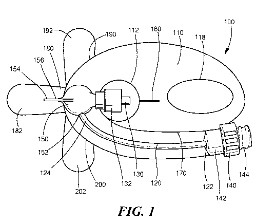
[0024] Fig. 1 schematically shows a catheter connection and stabilization
device, in
accordance with various embodiments of the present invention.
[0025] Fig. 2 schematically shows a side view of the catheter connection and
stabilization device shown in Figure 1, in accordance with some embodiments of
the present
invention.
7
CA 02920542 2016-02-04
WO 2015/023922 PCT/US2014/051217
[0026] Fig. 3 schematically shows a cross-sectional view of the docking pod
shown
in Figs. 1 and 2, in accordance with some embodiments of the present
invention.
[0027] Figure 4A schematically shows a first embodiment of a fluid pathway
formed
within the catheter connection and stabilization device, in accordance with
some
embodiments of the present invention.
[0028] Figure 4B schematically shows an alternative embodiment of a fluid
pathway
formed within the catheter connection and stabilization device, in accordance
with some
embodiments of the present invention.
[0029] Figure 5 schematically shows an alternative embodiment of a catheter
connection and stabilization device having multiple fluid pathways, in
accordance with
additional embodiments of the present invention.
[0030] Figures 6A schematically shows a first multiple fluid pathway
configuration
formed within the catheter connection and stabilization device, in accordance
with some
embodiments of the present invention.
[0031] Figures 6B schematically shows an alternative view of the multiple
fluid
pathway configuration shown in Figure 6A, in accordance with some embodiments
of the
present invention.
[0032] Figures 6C schematically shows a further alternative multiple fluid
pathway
configuration formed within the catheter connection and stabilization device,
in accordance
with some embodiments of the present invention.
[0033] Figure 7 schematically shows an alternative embodiment of a catheter
connection and stabilization device having multiple fluid pathways and medical
valves, in
accordance with additional embodiments of the present invention.
[0034] Figure 8A schematically shows an exploded view of an alternative
embodiment of an adherent substrate portion of catheter connection and
stabilization device,
in accordance with some embodiments of the present invention.
[0035] Figure 8B schematically shows an assembled top view of the adherent
substrate portion shown in Figure 8A, in accordance with some embodiments of
the present
invention.
8
CA 02920542 2016-02-04
WO 2015/023922 PCT/US2014/051217
[0036] Figure 8C schematically shows a cross sectional view of the adherent
substrate portion shown in Figures 8A and 8B along line A-A, in accordance
with
embodiments of the present invention.
[0037] Figure 9 is a flowchart showing a method of securing a catheter
connection
and stabilization device to a patient to stabilize a catheter, in accordance
with illustrative
embodiments of the present invention.
[0038] Figures 10A-10L show the catheter connection and stabilization device
shown
in Figure 1 being secured to a patient and stabilizing a catheter, in
accordance with
illustrative embodiments of the present invention.
Detailed Description of Specific Embodiments
[0039] In illustrative embodiments, a catheter connection and stabilization
device
may be secured to a patient to hold a catheter inserted into a patient's body
in place. Some
embodiments may include a medical valve and a male luer connector that are
fluidly
connected to one another via a fluid pathway extending through an adherent
substrate (e.g., a
dressing, tape, or similar substrate having an adhesive). In this manner,
various embodiments
may provide for the connection of a medical implement (e.g., a syringe) and
the transfer of
fluids in/out of the patient through the catheter and stabilization device.
Details of illustrative
embodiments are discussed below.
[0040] Fig. 1 schematically shows a catheter connection and stabilization
device 100
in accordance with some embodiments of the present invention. The
stabilization device 100
may include a dressing portion 110 (e.g., a transparent dressing or an
adherent substrate) that
may be applied to the patient. To that end, the dressing portion 110 may
include an adhesive
layer on the underside of the dressing portion 110 to secure the stabilization
device 100 to the
patient. Although any number of adhesives may be used to secure the
stabilization device
100 to the patient, the adhesive should be strong enough such that the
dressing portion 110
and the stabilization device 100 do not peel off the patient's skin during
regular movement
by the patient (e.g., manipulation of the hand, arm etc.). In some
embodiments, the portion of
the dressing portion 110 containing the fluid pathway 120 and medical valve
(discussed in
greater detail below) can have a skin contacting adhesive (e.g., a tacky
silicone adhesive) that
9
CA 02920542 2016-02-04
WO 2015/023922 PCT/US2014/051217
allows that portion of the dressing portion 110 to be removed from the skin
(e.g., to allow
access to the medical valve 140) and re-adhered to the skin once the medical
valve has been
accessed.
[0041] The dressing portion 110 may also have an opening 112 extending through
it
that allows a proximal portion of the catheter to pass through the
stabilization device 100.
Additionally, as discussed in greater detail below, the dressing portion 110
can be made from
multiple layers of film (e.g., a first layer 114 and a second layer 116, Figs.
4A/B) that define
a fluid pathway 120 extending through the dressing portion 110. The layers of
film (and thus
the dressing portion 110) should be flexible so that the dressing portion 110
can conform to
the contours of the patient's skin and allow for manipulation by the user when
attaching the
stabilization device 100 to the catheter. The layers of film can be made from
any number of
materials including, but not limited to polyurethane, polyester, polyethylene,
and/or PVC. To
prevent inadvertent stoppage of fluid flow through the stabilization device
100 and catheter,
the fluid pathway 120, in some embodiments, may be resistant to kinking. It is
important to
note that, although Figures 4A and 4B show only two layers of film, as
discussed in greater
detail below, other embodiments can have more than two layers and the fluid
pathways may
extend through the various layers of film.
[0042] The dressing portion 110 may be transparent so that the user is able to
see and
monitor the catheter insertion site, as well as view the fluid flow through
the fluid pathway
120. Additionally or alternatively, the dressing portion 110 may include a
transparent
window 118 on/through part of the dressing portion 110 for viewing/monitoring
the insertion
site. Although the size of this window 118 can depend on the type of catheter
used (e.g., a
long hub or a short hub catheter) and the specific application, in preferred
embodiments, the
window 118 should be at least 1" in diameter and/or length to provide a
sufficient viewing
area. Additionally, the window 118 may include an adhesive layer on at least a
portion of the
underside of the window 110. The adhesive layer may contain an antimicrobial
agent and/or
antiseptic (e.g., Chlorhexidine Gluconate) that interacts with the patient's
skin at the catheter
insertion site.
[0043] As mentioned above, some embodiments provide for the connection of a
medical implement and the transfer of fluids through a catheter inserted into
a patient. To
that end, the stabilization device 100 may include a male luer connector 130
that may be
CA 02920542 2016-02-04
WO 2015/023922 PCT/US2014/051217
connected to the catheter, and a medical valve 140 that may be connected to
the medical
implement and used to introduce fluids into and/or withdraw fluids from the
patient. As
shown in Figure 1, the fluid path 120 may extend between the valve 140 and the
male luer
connector 130 to allow the flow of fluid into/out of the patient and through
the stabilization
device 100. For example, the first end 122 of the fluid path 120 may be
fluidly connected to
the outlet 142 of the valve 140 and the other end 124 of the fluid path 120
may be fluidly
connected to the inlet of the male luer connector 130 (or a docking pod 150
which, in turn, is
fluidly connected to the male luer connector 130, discussed in greater detail
below).
[0044] Although any number of medical valves 140 can be used (e.g., positive
displacement valves, negative displacement valves, neutral displacement
valves, etc.), some
embodiments may use a simple split septum valve 140. As is known in the art, a
split septum
valve includes a septum obstructing the inlet 144 of the valve 140. To allow
flow through the
valve 140, the septum may include an aperture or a slit extending through it.
To that end, as
the medical implement (e.g., a needleless syringe) is connected to the valve
140, the medical
implement will deform the septum to open the aperture/slit and will partially
enter the inlet
144 of the valve 140. Once connected, the medical implement may be used to
transfer fluid
to/from the patient. Additionally or alternatively, some embodiments may
include a female
luer connector (not shown) located between the fluid pathway 120 and the valve
140 to allow
the medical valve 140 to be removed and/or replaced.
[0045] As mentioned above and as shown in Figures 1-3, some embodiments may
also include a docking pod 150 located between the second end 124 of the fluid
path 120 and
the male luer connector 130. In such embodiments, the fluid path 120 may be
fluidly
connected to the inlet 152 of the docking pod 150. To control fluid flow
through the
stabilization device 100 and the docking pod 150, the interior of the docking
pod 150 may
include a valve mechanism 157 and internal fluid path 151. For example, the
docking pod
150 may include a two-way pressure activated valve 157 (PAV) that includes a
flat
diaphragm 158 with a slit 159. The valve mechanism 157 prevents fluid flow
through the
docking pod 150 (e.g., through the internal fluid path 151) until it is
exposed to a large
enough pressure to open the slit through the diaphragm (e.g., a cracking
pressure). It is
important to note that a diaphragm 158 and slit 159 configuration should be
chosen such that
the patient's venous pressure is below the backward cracking pressure of the
valve
11
CA 02920542 2016-02-04
WO 2015/023922 PCT/US2014/051217
mechanism 157 to prevent the venous pressure from opening the slit
159/pressure activated
valve 157. Although a flat diaphragm 158 with a slit 159 may achieve the
functionality of a
two-way pressure activated valve, other two-way PAVs known in the art may also
be used
within the docking pod 150.
[0046] Like the dressing portion 110, the docking pod 150 may also include
adhesive
on the underside to allow the docking pod 150 to be secured to the patient.
Alternatively, the
docking pod may be mechanically joined to the topside of the dressing with the
docking pod
adhesive then located on the underside of the dressing for securing the
docking pod to the
patient (e.g., the docking pod adhesive may be located at least partially
beneath the docking
pod 150). Additionally, as discussed in greater detail below, the docking pod
150 may also
include a grasping fin 154 that may be used to hold the stabilization device
100 and help the
user secure the stabilization device 100 to the patient. To allow the grasping
fin 154 to be
moved/adjusted (e.g., when securing the stabilization device 100 to the
patient), the grasping
fin 154 may include a hinge 156 (e.g., a living hinge) that allows the fin 154
to flex/move
with respect to the rest of the docking pod 150.
[0047] The stabilization device 100, and particularly the dressing portion
110, can
also include a number of other features that make the stabilization device 100
easier to
connect to and stabilize the catheter, and secure to the patient. For example,
the dressing
portion 110 can include a strain relief member 160 (e.g., a cut partially
extending through the
dressing portion 110, a perforated area, a C-shaped notch, a V-shaped notch,
etc.) extending
from the opening 112 in the dressing portion 110. The strain relief member 160
allows the
dressing portion 110 to conform to the shape of the catheter without
wrinkling/folding or
tenting (e.g., creation of an air gap between the dressing portion 110 and the
skin of the
patient) of the dressing portion 110. Additionally, the dressing portion 110
can include a
perforated slit extending from the opening 112 and along the portion of the
dressing 110 that
defines the fluid path 120. Like the strain relief member 160, the perforated
slit 170 allows
the dressing portion 110 and the stabilization device 100 to better conform to
the contours of
the patient (e.g., the patient's arm). Additionally, if the perforated slit
170 is at least partially
separated, the slit 170 may allow for separation of the valve 140 from the
dressing portion
110 to facilitate connection to the valve 140 and reduce incidental forces
applied to the
dressing portion 110 adjacent to the transparent window 118.
12
CA 02920542 2016-02-04
WO 2015/023922 PCT/US2014/051217
[0048] A number of the components of the stabilization device 100 may include
one
or more adhesive formulations to secure the stabilization device 100 to the
patient. To
prevent the adhesive from inadvertently sticking to the wrong surface and/or
to prevent
bacteria and other contamination from sticking to the adhesive, the
stabilization device 100
may include one or more liners covering the adhesive. Each of the liners may
include a tab so
that the liner can be easily removed (discussed in greater detail below). For
example, the
stabilization device 100 can include a docking pod liner 180 and docking pod
liner tab 182
for the adhesive located beneath the docking pod 150 (e.g., on the bottom of
the docking pod
150 itself or on the underside of the portion of the dressing on which the
docking pod 150
sits), a dressing liner 190 and dressing liner tab 192 for the adhesive
located on the underside
of the dressing 110, and a fluid pathway liner 200 and fluid pathway liner tab
202 for the
adhesive area under the fluid pathway 120. Alternatively, a single liner may
be removed to
expose multiple adhesive locations and/or formulations.
[0049] As mentioned above, the at least two film layers 114/116 of the
dressing
portion 110 can define the at least one fluid pathway 120 extending between
the medical
valve 140 and the male luer connector 130 (or docking pod 150). To that end,
the fluid
pathway 120 may be an area in which the first and second layers 114/116 are
not adhered to
one another and/or one or more of the layers can be formed with a channel that
defines the
fluid pathway 120. For example, as shown in Figure 4A, the second layer 116
(or the first
layer 114) can be formed such that it defines a channel 117 through which the
fluid may
flow. In such embodiments, the first layer 114 (or the second layer 116 if the
first layer 114
is formed with the channel) may cover the channel 117 to complete the fluid
pathway 120.
Alternatively, as shown in Figure 4B, both the first layer 114 and the second
layer 116 may
be formed with a channel (e.g., the first layer 114 may be formed with a first
channel 115
and the second layer 116 may be formed with a second channel 117) that define
the fluid
pathway 120. To avoid/minimize device failure, the fluid pathway 120 should be
able to
withstand high pressures (e.g., at least 325 PSI). Additionally, to allow the
stabilization
device 100 and the fluid pathway 120 to be primed (discussed in greater detail
below), the
pathway 120 may include a venting element (not shown) within a wall of the
fluid pathway
that allows air to pass until the priming fluid contacts (and opens) the valve
mechanism 157
13
CA 02920542 2016-02-04
WO 2015/023922 PCT/US2014/051217
in the docking pod 150. In this manner, some embodiments of the fluid pathway
120 may be
self- priming.
[0050] As mentioned above, some embodiments of the present invention can have
more than one fluid pathway extending between the layers of the dressing
portion 110. For
example, as shown in Figure 5, some embodiments may include an additional
fluid pathway
125 (or multiple additional fluid pathways) fluidly connected to and extending
from the first
fluid pathway 120. This additional fluid pathway 125 may lead to a reservoir
126 (or an
access port, medical valve, etc.) that, in turn, may contain a liquid to be
administered to the
patient via the additional fluid pathway. Additionally or alternatively, the
reservoir 126 may
contain a drug (e.g., a lyophilized drug) that is to be mixed with the fluid
entering the
reservoir 126 and subsequently administered to the patient. The reservoir 126
and/or the
additional fluid pathway can also include an analyzing element that analyzes
the fluid that
comes into contact with the element. For example, the analyzing element may be
contained
within and/or form a wall of the reservoir 126 or the additional fluid pathway
125.
[0051] It is important to note that the additional fluid pathway 125 may
extend
through the same two layers of film as the first fluid pathway 120 (e.g.,
layers 114 and 116)
or the additional fluid pathway 120 may extend between different layers of
film. For
example, as shown in Figures 6A through 6C, the additional fluid pathway 125
may extend
between the second layer of film 116 and a third layer of film 119. To
facilitate fluid flow
between the fluid pathways 120/125 and between the film layers, as best shown
in Figure 6B,
the second film layer 114 can include an opening 113 that fluidly connects the
first fluid
pathway 120 and the additional fluid pathway 125 through the second film layer
114. In
some embodiments, the additional fluid pathway 125 can be a one-way fluid path
that allows
fluid to flow from the first fluid pathway 120 to the second fluid pathway 125
and/or
reservoir 126, but not back to the first fluid pathway 120.
[0052] Although Figures 6A-6C show embodiments having three layers 114/116/119
and two fluid paths (e.g., fluid pathway 120 and additional fluid pathway
125), other
embodiments can have more than three layers and more than two pathways. For
example,
some embodiments may include 4 or more layers of film and three or more fluid
pathways.
The fluid pathways may extend between (and be formed by) the same layers of
film or they
may extend between different layers of film (e.g., there may only be a single
fluid pathway
14
CA 02920542 2016-02-04
WO 2015/023922 PCT/US2014/051217
between any two layers, multiple fluid pathways between any two layers, or a
single fluid
pathway between some layers and multiple pathways between others).
[0053] As shown in Figure 7, in some embodiments, the catheter stabilization
device
100 may have multiple medical valves. In such embodiments, in addition to the
medical
valve 140 shown in Figure 1, the stabilization device 100 may include a second
medical
valve 145 to which a medical implement may be connected (e.g., to the inlet
146 of the
medical valve 145). Like the first medical valve 140, the second medical valve
145 may be
fluidly connected to the docking pod 150 via a fluid pathway 127 extending
between the two
or more film layers 114/116/119 forming the dressing portion 110 (e.g.,
between the first and
second film layers 114/116, between the second and third film layers 116/119,
etc.). Like the
first medical valve 140, the second medical valve 145 can be used to transfer
fluid between
the patient (e.g., into or out of the patient) and a medical implement.
[0054] As noted above, some embodiments of the catheter stabilization device
100
can have more than two layers of film, and the fluid pathway(s) can extend
within/through
the various layers. For example, as shown in Figures 8A-8C, the catheter
stabilization device
100 can have three layers of film that make up the dressing portion 110 (or
just the portion
containing the fluid path 120 extending between the valve 140 and the docking
pod 150, and
the portion on which the docking pod 150 resides). The dressing portion 110
(or just the
portion containing the flow path 120) may have a first/bottom layer 210 on
which the various
adhesive areas discussed above may be located (e.g., on the underside of the
first/bottom
layer 210), and a second/top layer 230. The first layer 210 and the second
layer 230 may be
essentially flat and envelope a third/middle layer 220 between them.
[0055] As best shown in Figure 8A, the third/middle layer 220 includes a
channel
222 formed within it. This channel 222 may form the fluid pathway 127, and may
extend
between two enlarged areas 224A/224B at either end of the channel 222.To
facilitate the
flow of fluid through the second/top layer 230 and facilitate fluid
communication with the
docking pod 150 and valve 140, the second/top layer may include through holes
232A/232B
that are aligned with the enlarged areas 224A/224B within the channel 222,
Figs. 8A and 8B.
For example, the docking pod 150 may be located at one end 240 of the
second/top layer
230, and the second/top layer 230 may have a first hole 232A that is aligned
with enlarged
area 224A to facilitate fluid communication between the channel 222 and the
inlet 152 of the
CA 02920542 2016-02-04
WO 2015/023922 PCT/US2014/051217
docking pod 150. Similarly, the medical valve 140 may be located on/secured to
the
opposing end 250 of the dressing portion 110, and the second/top layer 230 may
have a
second hole 232B that is aligned with enlarged area 224B to facilitate fluid
communication
between the channel 222 and the outlet 142 of the medical valve 140. To that
end, when
transferring a fluid to the patient, fluid may pass through the medical valve
140 and second
hole 232B, and into the channel 222. The fluid may then flow through the
channel 222, out
of the first hole 232A, and enter the inlet 152 of the docking pod 150.
[0056] Although Figures 8A-8C only show the portion of the dressing 110 on
which
the docking pod 150 is located and through which the fluid pathway 127
extends, it is
important to note that the three layer configuration may extend to the rest of
the dressing
portion 110 (e.g., the dressing portion shown in Figure 1). Alternatively, in
some
embodiments, only the first/bottom layer 210 and/or the second/top layer 230
may extend
further to form the remainder of the dressing portion 110 (e.g., the
third/middle layer may
only be located in the portion shown in Figures 8A to 8C and may not extend to
the rest of
the dressing portion 110).
[0057] It is important to note that, depending on the valve mechanism used
within the
docking pod 150 (if equipped) and/or the type of medical valve 140 used, the
stabilization
device 100 and the fluid pathway 120 may be exposed to changing pressures
during
disconnection and connection of the medical implement. For example, if the
medical valve
140 is a split septum valve, connection of the medical implement to the valve
140 may
increase the pressure within the fluid pathway 120 (e.g., because the medical
implement will
take up volume within the medical valve 140 and the pressure activated valve
in the docking
pod 150 is closed). Furthermore, once fluid transfer is complete and the
pressure activated
valve closes, removal of the medical implement from the valve 140 will create
a negative
pressure/vacuum within the fluid pathway 120.
[0058] To compensate for this change in pressure, in some embodiments, the
fluid
pathway 120 may be compliant such that it has a first volume when the medical
implement is
connected to the valve 140 and a second volume when the medical implement is
disconnected. For example, as the medical implement is connected to the valve
140 and the
pressure within the fluid pathway 120 increases, the fluid pathway 120 may
expand to
compensate for the increase in pressure. Conversely, as the medical implement
is
16
CA 02920542 2016-02-04
WO 2015/023922 PCT/US2014/051217
disconnected from the medical valve 140 and the pressure decreases, the fluid
pathway 120
may decrease in volume (but not fully collapse) to compensate for the decrease
in pressure.
In this manner, various embodiments of the present invention are able to
ensure that the
pressure differential between the downstream and upstream side of the pressure
activated
valve is not above the cracking pressure. Furthermore, by compensating for the
change in
pressure and volume created by connection/disconnection of the medical
implement, some
embodiments can attain neutral fluid displacement performance at the male luer
connector
130 upon connection and/or disconnection of the medical implement to the valve
140.
[0059] Figure 9 is a flowchart depicting a method for stabilizing a catheter
using a
stabilization device 100 in accordance with various embodiments of the present
invention.
Figures 10A-10L schematically show the catheter connection and stabilization
device 100 at
various stages of securement and stabilizing of the catheter. First, the user
(e.g., the medical
personnel) may connect a medical implement 610 to the valve 140 and flush
(e.g., prime) the
stabilization device 100, for example, with saline (Step 405, Fig. 10A). As
shown in Figure
10A, the stabilization device 100 may include a priming cap 620 located
on/secured to the
male luer connector 130. The priming cap 620 may be a vented cap that allows
air (and
priming fluid) to escape (e.g., as saline is introduced into the stabilization
device 100), but
helps prevent particulates from entering the male luer connector 130. If the
stabilization
device 100 has a second medical valve 145, a similar priming procedure may be
performed
on the second medical valve 145. Additionally, it is important to note that,
if the fluid
pathway 120 or the additional fluid pathway 145 includes a venting element,
air will exit the
fluid pathway(s) 140/145 via the venting element during the priming process to
prime the
fluid pathways 140/145.
[0060] Once the stabilization device is flushed/primed, the user may remove
the
priming cap 620 (Step 410, Figure 10B) and insert the catheter 630 into the
patient (e.g., into
the patient's arm) (Step 415, Figure 10C). It is important to note that prior
to inserting the
catheter 630, the insertion site should be properly cleaned per acceptable
medical practice.
Additionally, to preserve the injection site after insertion of the catheter
630, the user may
place gauze over the injection site and the location where the stabilization
device 100 will be
placed. The user may then connect the male luer connector 130 to the catheter
630 (Step 420;
Figure 10D).
17
CA 02920542 2016-02-04
WO 2015/023922 PCT/US2014/051217
[0061] As shown in Figure 10D-10H, when attaching the catheter 630 and
securing
the stabilization device 100, it may be helpful to fold a portion of the
stabilization device 100
over (or the stabilization device 100 can be packaged in the folded
configuration). For
example, the dressing portion 110 can be folded over such that the opening 112
is located
over the docking pod 150 and the grasping fin 154 extends through the opening
112 and
contacts the underside of the dressing portion 110. In this manner, the
grasping fin 154 acts
to keep the dressing portion 110 out of the way of the user during connection
of the catheter
630. Once the catheter 630 is attached to the male luer connector 130, the
user may then
remove the docking pod liner 180 (e.g., by pulling on the docking pod liner
tab 182) to
expose at least a portion of the adhesive beneath the docking pod, and press
the docking pod
150 against the skin of the patient to secure the docking pod 150 to the
patient (Step 425,
Figure 10E). It is important to note that the adhesive beneath the docking pod
may not be a
single adhesive formulation. For instance, a first portion may consist of a
low securement
strength adhesive, such as a silicone gel, and a second portion may consist of
a higher
securement strength adhesive, such as a high peel strength acrylic.
[0062] Once the docking pod 150 is adhered to the patient, it is desirable to
check
that the fluid flow through the stabilization device 100 and in the vein is
acceptable/adequate
(Step 430; Figure 10F). To that end, the user may gently inject 1-2 ml of
saline into the vein
to confirm adequate fluid flow. If the fluid flow is not adequate, the user
may adjust the
positioning of the catheter 630 within the vein by gently lifting the docking
pod 150 to
release the docking pod 150 from the patient's skin, and move the catheter 630
forward into
the vein while gently injecting another 1-2 ml of saline solution (Step 435).
Once the flow is
adequate, the user may, once again, secure the docking pod 150 to the
patient's skin (Step
440).
[0063] After the docking pod 150 is secured (or re-secured) and there is
adequate
flow within the vein, the user may disconnect the medical implement 610 from
the valve 140
(Step 445; Figure 10G), and tighten the luer connector 130 by turning the lock
collar 132
(Step 450; Figure 10H). To disconnect the medical implement 610, the user may
grasp the
valve 140 and turn the medical implement 610 counter-clockwise. As mentioned
above,
depending on the type of valve 140 used, disconnection of the medical
implement 610 may
decrease the pressure/create a vacuum within the fluid pathway 120 and the
fluid pathway
18
CA 02920542 2016-02-04
WO 2015/023922 PCT/US2014/051217
120 may decrease in volume to compensate for the pressure change. To tighten
the luer
connector 130, the user may grasp the catheter hub 632 (best shown in Figures
10E-G) and
turn a locking collar 132 on the male luer connector 130 clockwise until snug.
[0064] Once the medical implement 610 is disconnected and the male luer
connector
130 is tightened, the user may then secure the dressing portion 110 to the
patient (Step 455,
Figures 10I-10L). As mentioned above, in some embodiments, the dressing
portion 110 may
be folded over during connection of the male luer connector 130 to the
catheter 630. In such
embodiments, to secure the dressing portion 110 to the patient, the user may
flip the dressing
portion 110 back over and unfold the stabilization device 100 such that it
encompasses the
catheter insertion site (Figure 10I). To maintain control over and manipulate
the stabilization
device 100, the user may grasp the docking pod 150 and/or the grasping fin
154.
[0065] To begin securing the dressing portion 110 to the patient, the
user may
remove the dressing liner 190 (e.g., by pulling the dressing liner tab 192)
while applying a
slight pressure on the docking pod 150. The user may then gently rub down all
sections of
the dressing portion 110 to secure the dressing portion 110 to the patient's
skin (Figure 10J).
Similarly, the user can also remove the fluid pathway liner 200 (e.g., by
pulling the fluid
pathway liner tab 202) while applying a slight pressure on the docking pod
150, and rubbing
the fluid pathway 120 surface to secure the fluid pathway area to the
patient's skin (Figure
10K). The user may then re-rub all adhesive areas to ensure all of the
adhesive areas are fully
adhered to the patient (Figure 10L). If desired, the user may then
attach/secure additional
dressings to the patient to further cover the insertion site and stabilize the
catheter 630.
[0066] As mentioned above, once the stabilization device 100 is fully
secured to the
patient, the catheter 630 cannot be inadvertently moved. Additionally, the
medical implement
610 (e.g., the syringe) may be connected and disconnected as needed without
impacting the
placement/location of the catheter 630 and/or kinking the fluid pathway 120.
This, in turn,
helps to prevent injury to the patient and ensures that adequate fluid flow
through the
stabilization device 100, catheter 630, and vein is maintained. Furthermore,
because the
stabilization device 100 includes a medical valve 140, the medical implement
610 can be
easily re-attached to the stabilization device 100 at a later time to
introduce fluids into the
patient and/or withdraw fluids from the patient.
19
CA 02920542 2016-02-04
WO 2015/023922 PCT/US2014/051217
[0067] It is important to note that because various embodiments of the
present
invention encompass the catheter insertion site and secure the catheter 630 in
place, some
embodiments of the present invention are able to minimize bio-burden concerns,
reduce the
frequency of site infection (or other complication such as infiltration),
reduce catheter related
blood stream infections, and reduce clinical variation.
[0068] Additionally, embodiments of the present invention have numerous
advantages/benefits over prior art catheter stabilization device and
techniques. For example,
the above described embodiments are significantly easier to apply and provide
superior
catheter stabilization. Furthermore, some embodiments of the present invention
eliminate the
undesirable tube kinking and re-taping associated with prior art extension
sets that must be
intermittently pulled against the catheter hub (e.g., because of improper
placement).
[0069] The embodiments of the invention described above are intended to be
merely
exemplary; numerous variations and modifications will be apparent to those
skilled in the art.
All such variations and modifications are intended to be within the scope of
the present
invention as defined in any appended claims.