Note : Les descriptions sont présentées dans la langue officielle dans laquelle elles ont été soumises.
CA 02922450 2016-02-25
DESCRIPTION
PANEL DEVICE
TECHNICAL FIELD
[0001]
The present invention relates to panel devices, such as
breaker panels and control panels, incorporating an
interlocking mechanism that provides protection against
electric shock from any live part in conjunction with ON/OFF
movement of a molded case circuit breaker knob.
BACKGROUND ART
[0002]
A device is known as a conventional breaker panel,
in which protective covers of molded case circuit
breakers (hereinafter referred to as breakers) are
attached to an inner door in the housing side, the inner
door is locked by a tool-operating knob but can be opened
by releasing the tool-operating knob, and when the inner
door is opened, all of the protective covers of the
breakers are brought into an open state regardless of
the ON/OFF state of the breakers. Moreover, a control
center has been known which is configured in such a way
that breakers are provided with a handle for interlocking
1
CA 02922450 2016-02-25
linked with a safety door, the safety door is prohibited
from opening when the breakers are in the ON state, but
when in the OFF state, the safety door can be opened with
the internal interlock released (see Patent document 1,
for example).
PRIOR ART DOCUMENT
Patent document
[0003]
Patent document 1: Japanese laid-open Patent
Publication No. S61-236312 (see pp. 2-3, FIGs. 1-4)
DISCLOSURE OF THE INVENTION
Problem to be solved by the invention
[0004]
In a device using conventional technology as
described above, the door in the housing side can be
opened regardless of the ON/OFF state of the breakers,
if the lock of the tool-operating knob is released;
therefore, there has been a dander that live parts of
the breakers in the ON state can be touched in maintenance.
Moreover, the interlocking mechanism of the conventional
control center as described above is configured in such
a way that the door cannot be opened when the breakers
are in the ON state, but can be opened with the internal
2
CA292245020171
= interlock released when the breakers are in the OFF
state; therefore, the handle for interlocking is
necessary for each breaker, and some extra parts for
constituting the interlock are required in the housing
door side, thereby causing a problem in that the number
of parts increases and its configuration also becomes
complicated.
[0005]
The present invention has been made to solve the
foregoing problem, and aims at providing a panel device
that has a simple configuration and in addition can avoid
such a danger as its live parts being mistakenly touched,
thereby enabling maintenance to be carried out in safe.
Means for solving the problem
[0006]
A panel device according to the present invention
comprises a protective cover that has an insertion hole
for an ON/OFF knob of a molded case circuit breaker and
is formed to cover an exposed live part of the molded
case circuit breaker and provided with an engaging part
at a predetermined portion thereof; a cover support
member that openably and closably supports the protective
cover; and a cover locking member that engages with and
physically contacts the engaging part when the protective
cover is closed, so as to restrict turning of the
protective cover, and the cover locking member is
released from physical contact with the engaging part
when the protective cover is opened; wherein
3
either one of the protective cover, and the cover support
member is movably provided in conjunction with movement of
the ON/OFF knob, and the engaging part and the cover locking
member are engaged with each other or released from each
other by the movement of the any one of those.
In another embodiment, the present invention provides a
panel device, comprising:
a protective cover including a front face that has an
insertion hole for an ON/OFF knob of a molded case circuit
breaker, the protective cover formed to cover an exposed
live part of the molded case circuit breaker and provided
with an engaging part at a predetermined portion thereof;
a cover support member that openably and closably
supports the protective cover; and
a cover locking member that engages with and physically
contacts the engaging part when the protective cover is
closed, so as to restrict turning of the protective cover,
and the cover locking member is released from physical
contact with the engaging part when the protective cover is
opened; wherein
the cover locking member is movably provided in
conjunction with movement of the ON/OFF knob, the engaging
part and the cover locking member are engaged with each
other or released from each other by the movement of the
cover lock member, and the protective cover is opened and
closed as turnably supported by the cover support member.
Advantage of the invention
[0007]
According to the present invention, since the interlock
of the protective cover provided for each molded case
circuit breaker can be released one by one; therefore, the
4
CA 2922450 2018-04-30
C4,1292245020171
danger of mistakenly touching live parts of other breakers
can be avoided, so that maintenance can be carried out in
safe. In
addition, any one of the protective cover, the
cover support member and the cover locking member is movably
provided in conjunction with the movement of the ON/OFF
knob, and the engaging part and the cover locking member can
be engaged with each other or released from each other by
the movement of the any one of those, so that the
configuration of the device becomes simple and the number of
parts can be decreased.
BRIEF DESCRIPTION OF THE DRAWINGS
4a
CA 02922450 2016-02-25
[0008]
FIGS. lA and 1B are views showing the entire configuration
of a panel device according to Embodiment 1 of the present
invention;
FIGS. 2A, 2B, and 2C are views for explaining an
interlocking mechanism of a protective cover of the panel device
according to Embodiment 1 of the present invention;
FIGS .3A, 3B, 3C, and 3D are views for explaining in
detail the essential part of the interlocking mechanism
shown in FIGS. 2A, 2B, and 20;
FIGS. 4A, 4B, and 40 are views for explaining an
interlocking mechanism of a protective cover of a panel
device according to Embodiment 2 of the present
invention;
FIGS. 5A, 5B, 50, and 5D are views for explaining in
detail the essential part of the interlocking mechanism
shown in FIGS. 4A, 4B, and 40;
FIGS. 6A, 6B, and 6C are views for explaining an
interlocking mechanism of a protective cover of a panel
device according to Embodiment 3 of the present
invention;
FIGS. 7A, 7B, and 7C are views for explaining in detail
the essential part of the interlocking mechanism shown
in FIGS. 6A, 6B, and 60;
FIGS. 8A, 8B, and BC are views for explaining an
5
CA 02922450 2016-02-25
interlocking mechanism of a protective cover of a panel
device according to Embodiment 4 of the present
invention;
FIGS. 9A and 9B are views for explaining in detail
the essential part of the interlocking mechanism shown
in FIGS. 8A, 8B, and 8C;
FIGS. 10A and 10B are views for explaining an
interlocking mechanism of a protective cover of a panel
device according to Embodiment 5 of the present
invention;
FIGS. 11A and 11B are views for explaining in detail
the essential part of the interlocking mechanism shown
in FIGS. 10A and 10B;
FIGS. 12A and 12B are another views for explaining in
detail the essential part of the interlocking mechanism
shown in FIGS. 10A and 10B;
FIGS. 13A and 13B are views for explaining an
interlocking mechanism of a protective cover of a panel
device according to Embodiment 6 of the present
invention;
FIGS. 14A and 14B are views for explaining in detail
the essential part of the interlocking mechanism shown
in FIGS. 13A and 13B;
FIGS. 15A, 15B, 15C, and 15D are another views for
explaining in detail the essential part of the
6
CA 02922450 2016-02-25
interlocking mechanism shown in FIGS. 13A and 133;
FIGS. 16A, 163, and 160 are views for explaining an
interlocking mechanism of a protective cover of a panel
device according to Embodiment 7 of the present
invention;
FIGS. 17A and 17B are views for explaining in detail
the essential part of the interlocking mechanism shown
in FIGS. 16A, 163, and 160;
FIGS. 18A and 18B are another views for explaining in
detail the essential part of the interlocking mechanism
shown in FIGS. 16A, 163, and 160;
FIGS. 19A, 19B, and 190 are views for explaining an
interlocking mechanism of a protective cover of a panel
device according to Embodiment 8 of the present
invention;
FIGS. 20A and 20B are views for explaining in detail
the essential part of the interlocking mechanism shown
in FIGS. 19A, 193, and 190; and
FIGS. 21A and 21B are another views for explaining in
detail the essential part of the interlocking mechanism
shown in FIGS. 19A, 19B, and 190.
BEST MODE FOR CARRYING OUT THE INVENTION
[0009]
Embodiment 1.
7
CA 02922450 2016-02-25
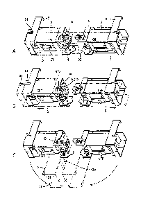
FIGS. lA and 1B are views showing the entire configuration
of a panel device according to Embodiment 1 of the present
invention; FIG. lA is a plan view and FIG. 13 is a
perspective view. FIGS. 2A, 28, and 2C are views for
explaining an interlocking mechanism of a protective
cover of the panel device according to Embodiment 1 of
the present invention; FIG. 2A is a perspective view
showing a state of a breaker being ON and a protective
cover closing; FIG. 2B is a perspective view showing a
state of the breaker being OFF and the protective cover
sliding outward; and FIG. 2C is a perspective view
showing a state of the breaker being OFF and the
protective cover opening. In FIGS. lA and 113, a breaker
panel 1as the panel device is configured using a housing
11 with an opening/closing door ha at its front part,
breakers 2, which are a plurality of molded case circuit
breakers housed inside the housing 11, and a protective
cover 3 that individually covers an exposed live part
of each of the breakers 2.
[0010]
Additionally, the paired breakers 2 arranged right
and left are disposed in this example point-symmetrically
to each other in such a way that one of the breakers
becomes ON when its ON/OFF knob 21 is moved inward (toward
the other breaker of the breakers 2 arranged right and
8
CA 02922450 2016-02-25
left) and becomes OFF when the ON/OFF knob 21 is moved
outward of the breaker panel 1. Additionally, for the
sake of convenience, when the paired breakers 2 are
arranged right and left so that ON/OFF directions of the
ON/OFF knob 21 become the right and left directions, a
direction toward the other breaker viewed from any one
of the breakers is referred to as the "inward" direction
and the opposite direction of that is referred to as the
"outward" direction in this document.
[0011]
FIGS.3A, 3B, 30, and 3D are views for explaining in
more detail the interlocking mechanism shown in FIGS. 2A,
2B, and 2C; the protective cover 3 is formed in a U-shape
in cross section as shown in FIG. 30; elongated holes
3a through which the turning central axis for opening
and closing the protective cover passes are made
vertically symmetrically in the upper side and lower side
sections shown in FIG. 30; in addition, round holes 3b
(holes for circling screws, hereinafter referred to as
the same) are similarly made vertically symmetrically,
through which sems screw 92a that engages with a cover
support member 4 described later is inserted; and in the
front section of the cover is provided an insertion hole
3c through which the ON/OFF knob, an ON/OFF lever of the
breakers 2, is inserted. Furthermore, engaging parts 31,
9
CA 02922450 2016-02-25
which are tongue-shaped protrusions, are formed as shown
in FIG. 3C symmetrically facing each other at upper and
lower end portions in the opposite side of the elongated
holes 3a (outer side of the panel) in the upper side and
lower side sections of the protective cover 3; a
monitoring window 32 for monitoring the live part is
formed in the front section in the side of the elongated
holes 3a (inner side). The engaging parts 31 can be
provided in predetermined portions decided at suitable
required locations distant from the turning center of
the protective cover 3 so as to match with the location
and shape of locking parts 51 of a cover locking member
5 described later.
[0012]
Additionally, the insertion hole 3c is shaped in a
rectangular elongated in the moving directions of the
ON/OFF knob 21 (right and left directions here). Taking
the left-hand side breaker of the breakers 2 in the figure,
for example, the insertion hole is formed in such a way
that when the ON/OFF knob 21 is brought into the ON state
(turned on) after the protective cover 3 is slid to the
inner end portion (in the right direction) and closed,
the right end portion of the insertion hole nearly touches
the right lateral face of the ON/OFF knob 21. Thereby,
the protective cover 3 is restricted not to slide outward
CA 02922450 2016-02-25
(in the left direction) when the ON/OFF knob 21 is in
the ON state. Additionally, the insertion hole 3c is
formed to have a length in the right and left directions
in such a way that the left end portion thereof touches
the left lateral face of the ON/OFF knob 21 even when
the ON/OFF knob 21 is brought down in the OFF direction
from the foregoing state, thereby prohibiting the
protective cover 3 from moving outward.
[0013]
The cover support member 4 made of a sheet metal is
fixed to the housing 11 together with the breakers 2,
and screw holes 4a for supporting the protective cover
3 and arc-shaped grooves 4b centering at these screw holes
4a are provided vertically symmetrically in upper and
lower bent sections protruding frontward as shown in FIG.
3D. The cover locking member 5 that is made of a sheet
metal and U-shaped in a size capable of fitting inside
the protective cover 3 formed in the U-shape in cross
section is fixed to suitable fixing portions of the
breakers 2, the housing 11 or the like as shown in FIGS.
2A, 2B, and 20, and provided with the locking parts 51,
such as notches or grooves, which are formed at upper
and lower two locations by cutting away portions thereof
from the outer side toward the inner side, and engage
with their respective engaging parts 31 of the protective
11
CA 02922450 2016-02-25
cover 3 when the cover is closed, so as to restrict turning
of the protective cover 3.
[0014]
As shown in FIGS.3A, 3B, 30, and 3D, a cylindrical
spacer 91 is inserted through each of the elongated holes
3a of the protective cover 3, furthermore a sems screw
920, which is a screw assembled with a washer, is inserted
through the center of the spacer 91, and fastened and
fixed via a nylon washer 93 to the screw holes 4a made
in the cover support member 4. Thereby, the protective
cover 3 becomes able to slide along the elongated holes
3a and also turn around the sems screw 920. On the other
hand, sems screw 92a inserted through each of the round
holes 3b of the protective cover 3 from the front side
is fitted with the cylindrical spacer 91 and a washer
94 from the back side and then fastened and fixed by a
nut 96 as shown in FIG. 3B.
[0015]
Additionally, in order to distinguish two sems screws
numbered with 92 from each other for the sake of
convenience in explaining operation, the screw that
serves as the turning central axis when the protective
cover 3 is opened/closed is referred to as the "sems screw
920" and the screw that circles around the sems screw
920 together with the protective cover 3 is referred to
12
CA 02922450 2016-02-25
as the "sems screw 92a" in this Embodiment 1. Since
configurations other than the above-described
interlocking mechanism are the same as those of the
conventional device, their explanation will be omitted.
[0016]
Next, the operation of Embodiment 1 configured as
described above will be explained. First, when the
breakers 2 are in the ON state, the spacer 91 fixed at
the round holes 3b part of the protective cover 3 lies
at the position A shown in FIG. 2A and FIG. 3A, and the
s ems screw 920 part that is inserted through the elongated
holes 3a of the protective cover 3 and slidably and
turnably fixes the protective cover 3 lies at the position
in the outer side of the elongated holes 3a (left side
in FIG. 3A). The engaging parts 31, which are protrusions
formed at the upper and lower portions in the back side
of the protective cover 3, are fitted into the locking
parts 51 of the cover locking member 5 and locked in this
state as shown in FIG. 2A; therefore, the protective cover
3 cannot be opened.
[0017]
The ON/OFF knob 21 is brought down inward when the
breakers 2 are in the ON state, the inner side end portion
(right end portion in FIG. 30) of the insertion hole 3c
that is made in the front section of the protective cover
13
CA 02922450 2016-02-25
3 and through which the ON/OFF knob 21 is inserted touches
the ON/OFF knob 21 and is restrained, whereby the
protective cover 3 cannot be slid outward, and as a result,
the protective cover is brought into a state of being
unable to open. Therefore, the not-shown live part of
the breakers 2 is covered by the protective cover 3.
[0018]
Next, when the breakers 2 are brought into the OFF
state, the ON/OFF knob 21 is brought down outward as shown
in FIG. 2B, whereby the protective cover 3 becomes ready
to slide outward by the same distance as the ON/OFF knob
21 has moved from the inner side to the outer side. When
the protective cover 3 is manually slid outward as shown
by the arrow in FIG. 2B, the spacer 91 and the sems screw
92a that are fixed at the round holes 3b come to the
position B; meanwhile, the s ems screw 920 that is inserted
through the elongated holes 3a and serves as the turning
central axis of the protective cover 3 moves to the inner
position of the elongated holes 3a. The engaging parts
31, which are protrusions formed at the upper and lower
portions in the back side of the protective cover 3, are
released from the locking parts 51 of the cover locking
member 5, so that the protective cover 3 becomes able
to be opened.
[0019]
14
CA 02922450 2016-02-25
When the end portion in the outer side of the
protective cover 3 is pulled frontward (front side), the
protective cover 3 turns around the sems screw 920 that
has moved to the position in the inner side of the
elongated holes 3a, and the spacer 91 inserted through
the round holes 3b of the protective cover 3 moves to
the position C along the arc-shaped grooves 4b of the
cover support member 4, thereby enabling the protective
cover 3 to open. The spacer 91 and the sems screw 92a
at the round holes 3b part of the protective cover 3 stop
at the position C that is the end portion of the grooves
4b, whereby the opening angle of the protective cover
3 is restricted, and also the sems screw 920 part inserted
through the elongated holes 3a of the protective cover
3 serves as a fulcrum; therefore, when the protective
cover 3 is in the open state, the protective cover 3
becomes unable to move inward, so as to avoid interfering
with its neighboring protective cover.
[0020]
If the breakers 2 are mistakenly turned on when the
protective cover 3 is in the open state and then the
protective cover is intended to be closed in that state,
the ON/OFF knob 21 hits the back of the protective cover
3 and the cover cannot be closed. Furthermore, if the
protective cover 3 is intended to be closed with the cover
CA 02922450 2016-02-25
slid inward, the engaging parts 31 provided at the upper
and lower portions in the back side of the protective
cover 3 hit the cover locking member 5; the protective
cover 3 is structurally made unable to be closed even
in either case. Moreover, by providing the protective
cover 3 with the monitoring window 32, change in color
and the like of terminals of the internal live part can
be inspected in safe from the outside.
[0021]
In Embodiment 1 as described above, the elongated
holes 3a are made in the protective cover 3 so as to
provide the cover slidably with respect to the cover
support member 4, and also the insertion hole 3c of the
protective cover 3 interferes with the ON/OFF knob 21
when the breakers 2 are in the ON position, thereby making
the protective cover 3 unable to slide. Furthermore, the
engaging parts 31, which are protrusions formed at the
upper and lower portions in the back side of the
protective cover 3, are fitted into the locking parts
51 of the cover locking member 5, thereby making the
protective cover 3 unable to open.
[0022]
By doing in this way, opening/closing conditions of
the protective cover 3 can be set, without providing the
breaker 2 with a handle for interlocking, using only
16
CA 02922450 2016-02-25
ON/OFF movement of the ON/OFF knob 21; the protective
cover 3 cannot be opened when the breakers are in the
ON state, but can be opened only when the breakers in
the OFF state. Since the interlocking mechanism for the
protective cover 3 provided on each of the breakers 2
can be released breaker by breaker, there is no danger
such as mistakenly touching live parts of other breakers
during maintenance, so that maintenance can be carried
out in safe. Moreover, every member necessary for the
above can be easily formed by, for example, metal pressing
and the configuration can be simplified, so that the
number of parts can be decreased. Furthermore, the
breakers can use regular standardized parts, so that an
effect of providing breakers at low cost can be also
produced.
[0023]
Embodiment 2.
FIGS. 4A, 4B, and 4C are views for explaining an
interlocking mechanism of a protective cover of a panel
device according to Embodiment 2 of the present
invention; FIG. 4A is a perspective view showing a state
of the breaker being ON and the protective cover closing;
FIG. 48 is a perspective view showing a state of the
breaker being OFF and the protective cover sliding
17
CA 02922450 2016-02-25
outward; and FIG. 40 is a perspective view showing a
state of the breaker being OFF and the protective cover
opening. FIGS. 5A, 55, 50, and 5D are views for explaining
in more detail the interlocking mechanism shown in FIGS.
4A, 4B, and 40; FIG. 5A is a detailed perspective view
of the interlocking mechanism; FIG. 5B is an arrow view
taken in the X direction of FIG. 5A; FIG. 50 is a detailed
view of the portion A encircled in FIG. 55; and FIG. 5
D is a detailed view of the portion B encircled in FIG.
5R. Additionally, the protective cover 3 in Embodiment
1 is made to be manually slid outward after the breakers
2 are brought into the OFF state; however, in this
Embodiment 2, when the breakers 2 are brought into the
OFF state, the protective cover 3A also slides at the
same time so as to be able to open.
[0024]
As shown in FIGS. 4A, 4B, and 40, a cover support
member 4A is provided with a rectangular hole 4c that
is formed to engage with the ON/OFF knob 21 so that the
cover support member 4A itself can slide in the right
and left directions of the figure in conjunction with
the ON/OFF knob 21, the screw holes 4a (shown in FIG.
5A , FIG. 50) at which the protective cover 3A is screwed
by a screw 97 that turnably supports the cover at upper
and lower two locations as shown in FIG. 5B, and elongated
18
CA 02922450 2016-02-25
holes 4d made at two locations through which the sems
screw 92 that slidably supports the cover support member
4A with respect to the breakers 2 is inserted. The
insertion hole 3c (shown in FIG. 4C), which is the same
as that of Embodiment 1, is made in the front section
of the protective cover 3A; at the upper and lower
sections thereof are provided round holes 3d each of which
the screw 97 that turnably supports the protective cover
3A is inserted. The cylindrical spacer 91 is inserted
through each of the round holes 3d at the upper and lower
sections of the protective cover 3A as shown in FIG. 5
C, furthermore the screw 97 is inserted through the spacer
91, and the protective cover is fixed to the upper and
lower screw holes 4a of the cover support member 4A by
the screw 97 via the nylon washer 93, thereby enabling
the protective cover 3A to turn with the spacer 91 (screw
97) serving as the axis.
[0025]
The ON/OFF knob 21 of the breakers 2 is inserted
through the rectangular hole 4c of the cover support
member 4A, and the elongated holes 4d made at the two
locations are fixed as shown in FIG. 5D. First, a large
washer 94L that is larger than the washer 94 in diameter,
the cylindrical spacer 91 and the washer 94 are stacked
up in this order at each of fixing holes 22 of the breakers
19
CA 02922450 2016-02-25
2, on which another spacer 91 is placed, and this spacer
91 is made to pass through the elongated holes 4d of the
cover support member 4A. Then, another washer 94 is placed
on this spacer 91 and these are fastened together with
the breakers 2 by the sems screw 92. By doing in this
way, the cover support member 4A becomes able to slide
right and left in conjunction with ON/OFF movement of
the breakers 2. Since the protective cover 3A is fixed
to the cover support member 4A, the cover slides right
and left in FIGS. 4A, 4B, and 4C together with the cover
support member 4A. Other configurations, such as the
cover locking member 5, are the same as those of
Embodiment 1, so their explanation will be omitted.
[0026]
In Embodiment 2 as configured above, the ON/OFF knob
is brought down inward when the breakers 2 are in the
ON state, and at the same time, the cover support member
4A and the protective cover 3A also slide inward. In this
state, the enqaging parts 31, which are tongue-shaped
protrusions provided at the upper and lower portions in
the back side of the protective cover 3A, are fitted into
the locking parts 51 of the cover locking member 5,
thereby making the protective cover 3A unable to open.
When the breakers 2 are brought into the OFF state, the
ON/OFF knob is brought down outward, and the cover support
CA 02922450 2016-02-25
member 4A and the protective cover 3A also slide outward
at the same time. When these slide outward, the engaging
parts 31 provided at the upper and lower portions in the
back side of the protective cover 3A are released from
the locking parts 51 of the cover locking member 5,
thereby enabling the protective cover 3A to open by
pulling it frontward.
[0027]
If the breakers 2 are mistakenly turned on when the
protective cover 3A is in the open state and then the
protective cover 3A is intended to be closed in this state,
the ON/OFF knob 21 is brought down inward, and at the
same time, both of the cover support member 4A and the
protective cover 3A come into a state of sliding inward.
Even if the protective cover 3A is intended to be closed
in this state, the engaging parts 31 provided at the upper
and lower portions in the back side of the protective
cover 3A hit an upper end portion of the cover locking
member 5, thereby making the protective cover 3A unable
to close. Additionally, the same as Embodiment 1, change
in color and the like of internal terminals can be
inspected in safe, without opening the protective cover
3A, from the outside through the monitoring window 32
provided in this protective cover 3A.
[0028]
21
CA 02922450 2016-02-25
According to Embodiment 2 as described above,
opening/closing conditions of the protective cover 3 can
be set, without providing a handle for interlocking on
the breakers 2, by only the ON/OFF movement of the ON/OFF
knob 21; the protective cover 3A cannot be opened when
the breakers 2 are in the ON state, but can be opened
only when the breakers 2 in the OFF state. Since the
interlocking mechanism for the protective cover 3A
provided on each of the breakers 2 can be released breaker
by breaker, there is no danger such as mistakenly touching
live parts of other breakers during maintenance, so that
maintenance can be carried out in safe. Moreover, the
configuration of the device becomes simple, the number
of parts can be decreased, and the breakers 2 can use
regular standardized parts, which will also produce an
effect capable of providing breakers at low cost.
[0029]
Embodiment 3.
FIGS. 6A, 6B, and 6C are views for explaining an
interlocking mechanism of a protective cover of a panel
device according to Embodiment 3 of the present
invention; FIG. 6A is a perspective view showing a state
of the breaker being ON and the protective cover closing;
FIG. 6B is a perspective view showing a state of the
22
CA 02922450 2016-02-25
breaker being OFF and the protective cover opening; and
FIG. 6C is a perspective view showing in detail the
interlocking mechanism. FIGS. 7A, 7B, and 70 are views
for explaining in detail the essential part of the
interlocking mechanism shown in FIGS. 6A, 63, and 60;
FIG. 7A is a detailed view of the portion A encircled
in FIG. 6A; and FIG. 7B is an arrow view taken in the
Y direction of FIG. 63. Additionally, the main difference
between Embodiment 3 and Embodiments 1 and 2 described
above is that a protective cover 3B does not slide but
is made to open from the upper side toward the lower side,
and a cover locking member 53 is configured to be able
to slide in conjunction with the ON/OFF knob 21, thereby
controlling opening/closing of the protective cover 33.
[0030]
In FIGS. 6A, 6B, and 60, the cover locking member 5B
is provided with in the front section thereof a
rectangular hole 5a that is formed to engage with the
ON/OFF knob 21 so as to be able to move right and left
in conjunction with movement of the knob, and at two
locations thereof elongated holes 5b that support the
cover locking member 5B slidably with respect to the
breakers 2, and furthermore locking parts 51T, which are
tongue-shaped protrusions projecting upward, are
provided at two locations. The protective cover 3B is
23
CA 02922450 2016-02-25
provided with in the right and left lower sections thereof
round holes 3d (not shown) for turning, in the front
section thereof the insertion hole 3c through which the
ON/OFF knob 21 shown in FIG. 6C is inserted (see FIG.
6B), and at right and left two locations in the upper
section thereof engaging parts 31B, which are L-shaped
notches for receiving and engaging with the locking parts
51T, as well as the monitoring window 32. As shown in
FIG. 6C, a support member that turnably supports the
protective cover 3B includes a cover support member 4B1
that is attached to both outer side portions of the paired
breakers 2 arranged side by side and a cover support
member 482 that is attached to the central portion
thereof; both are rigidly fixed to the breakers 2 and
cannot be moved. Additionally, the nearly T-shaped cover
support member 4B2 is shared between the breakers 2 in
the right and left sides.
[0031]
In assembling, the spacer 91 and the washer 94 are
placed at first on a fixing part of the breakers 2 as
shown in FIG. 7B, furthermore another spacer 91 is placed
on that, and this spacer 91 is inserted through one of
the elongated holes 5b of the cover locking member 5B.
Then, another washer 94 is placed on this spacer 91, and
these are fixed together with the breakers 2 by the sems
24
CA 02922450 2016-02-25
screw 92. The ON/OFF knob 21 of the breakers 2 is inserted
through the rectangular hole 5a in the front section of
the cover locking member 5B. Thereby, the cover locking
member 5B becomes able to slide right and left in
conjunction with the movement of the ON/OFF knob 21.
[0032]
An internally-threaded screw hole 4a (not shown) is
made in the cover support member 4B1 attached to both
sides of the breakers, and the cover support member 4B2
attached to the central part is provided with a round
hole 4e. (Additionally, none of round hole, spacer,
washer, nut, etc are not given reference numerals in the
drawings in this paragraph.) In both sides of the
protective cover 3B, the spacer 91 is inserted through
the round holes 3d made in the protective cover 3B, and
the sems screw 92 is inserted through the spacer 91 and
screwed to the screw hole 4a of the cover support member
4B1. In the central side of the protective cover 3B, the
spacer 91 is inserted through the round holes 3d in the
central side of the right-hand side and the left-hand
side protective cover 3B and the round hole 4e of the
cover support member 4B2 at the same time so as to fix
these using the sems screw 92, the washer 94 and the nut
96. By doing in this way, the right-hand side and the
left-hand side protective cover 3B become able to open
CA 02922450 2016-02-25
from the upper side toward the lower side.
[0033]
In Embodiment 3 as configured above, the ON/OFF knob
is brought down inward when the breakers 2 are in the
ON state, and accordingly the cover locking member 5B
also slides inward at the same time. In this state, the
locking parts 51T provided at the two locations in the
upper side of the cover locking member 5B are fitted into
the engaging parts 31B provided at the two locations in
the upper side of the protective cover 3B, thereby making
the protective cover 3B unable to open (see FIG. 6C).
When the breakers 2 are brought into the OFF state,
the ON/OFF knob 21 of the breakers 2 is brought down
outward, and accordingly the cover locking member 5B
slides outward at the same time. When the cover locking
member 5B slides outward, the locking parts 51T provided
at the two locations in the upper side of the cover locking
member 5B are released from the engaging parts 31B
provided at the two locations in the upper side of the
protective cover 3B, thereby making the protective covers
3B able to open.
[0034]
If the breakers 2 are mistakenly turned on when the
protective cover 3B is in the open state and then the
protective cover 3B is intended to be closed in this state,
26
CA 02922450 2016-02-25
the ON/OFF knob 21 is brought down inward by the turn-on
operation, and accordingly the cover locking member 5B
is also brought into a state of sliding inward. Therefore,
if the protective cover 3B is intended to be closed in
this state, the locking parts 51T provided at the two
locations in the upper side of the cover locking member
5B are brought into a state of not engaging with the
engaging parts 31B provided at the two locations in the
upper side of the protective cover 3B, thereby making
the protective cover 3B unable to close. In addition,
change in color and the like of internal terminals can
be inspected in safe, without opening the protective
cover 3B, from the outside through the monitoring window
32.
[0035]
According to Embodiment 3 as described above,
opening/closing conditions of the protective cover 3 can
be set, without providing a handle for interlocking on
the breakers 2, by only the ON/OFF movement of the ON/OFF
knob 21; the protective cover 3B cannot be opened when
the breakers 2 are in the ON state, but can be opened
only when the breakers 2 are in the OFF state. Since the
interlocking mechanism for the protective cover 3B
provided on each of the breakers 2 can be released breaker
by breaker, there is no danger such as mistakenly touching
27
CA 02922450 2016-02-25
live parts of other breakers during maintenance, so that
maintenance can be carried out in safe. Moreover, the
configuration of the device becomes simple, the number
of parts can be decreased, and the breakers 2 can use
regular standardized parts, thereby also producing an
effect of providing breakers at low cost.
[0036]
Embodiment 4.
FIGS. 8A, 8B, and 8C are views for explaining an
interlocking mechanism of a protective cover of a panel
device according to Embodiment 4 of the present
invention; FIG. 8A is a perspective view showing a state
of the breaker being ON and the protective cover closing;
FIG. 8B is a perspective view showing a state of the
breaker being OFF and the protective cover sliding
outward; and FIG. 8C is a perspective view showing a
state of the breaker being OFF and the protective cover
opening. FIGS. 9A and BE are views for explaining in
more detail the interlocking mechanism shown in FIGS.
8A, 8B, and BC; FIG. 9A is a detailed perspective view
of the interlocking mechanism; and FIG. 9B is an arrow
view of the essential part thereof taken in the Z
direction in FIG. 9A. Additionally, in this Embodiment
4, a protective cover 3C and its turning central axis
28
CA 02922450 2016-02-25
are made movable in conjunction with movement of the
ON/OFF knob 21, and an engaging part 31C is configured
using an engaging pin disposed in parallel to the turning
central axis at a radially predetermined distance from
the axis. On the other hand, a cover locking member 5C
is configured using a sheet guide member having a locking
part 51S made of a slit guide groove formed including
a straight section that is parallel to the directions
to guide to slide the engaging pin and has the same length
as the sliding distance of the engaging pin and an arc
section that continuously connects to the straight
section.
[0037]
As shown in FIG. 9A, the protective cover 3C with a
U-shaped cross section is provided with round holes 3d
each located in the upper side and lower side sections
thereof and an engaging part 31C that is the engaging
pin and erected at the radially predetermined distance
from the round holes 3d; in the front section thereof
is provided the insertion hole 3c, the same as that of
Embodiment 1 (shown in FIG. 8C), through which the ON/OFF
knob 21 is inserted. Acover support member 4C is provided
with the elongated holes 4d that are elongated in the
right and left directions and each located in the upper
and lower sections thereof. As shown in FIG. 9B, the round
29
CA 02922450 2016-02-25
holes 3d of the protective cover 30 are laid on their
respective elongated holes 4d (not shown) via the nylon
washer 93, the cylindrical spacer 91 is inserted from
the back side, and these are fixed together by the sems
screw 92, the washer 94 and the nut 96. The cover support
member 40 is fixed to the breakers 2 and does not move.
The cover locking member 50 is made of a sheet material
having the locking part 51S provided with the guide groove
that engages with the engaging part 310 and is formed
including the straight section 51a that is parallel to
the elongated directions of the holes 4d, that is, the
sliding directions of the protective cover 30, and has
the same length as the sliding distance of the cover,
and the arc section 51b that continuously connects to
the straight section 51a. The cover locking member 50
is fixed to the housing 11 (shown in FIGS. 1A and 1B)
by a not-shown fixing member.
[0038]
Then, the engaging part 31C erected on the protective
cover 30 is fitted into the locking part 51S of the cover
locking member 50 as shown in FIG. 9A. Additionally, let
one end portion of the straight section 51a of the locking
part 51S be a position A, the connecting point of the
straight section Sla with the arc section 51b, a position
B, the other end portion of the arc section 51b, a position
CA 02922450 2016-02-25
C, the inner end portion of the elongated holes 4d, a
position E, and the outer end portion thereof, a position
F. In a state of the protective cover 30 sliding inward
and closing, the turning central axis of the protective
cover 30 lies at the position E and the engaging part
310, which is the engaging pin, lies at the position A.
The turning central axis of the protective cover 30 moves
to the position F and the engaging part 310 to the position
B when the protective cover 30 is slid outward. The
curvature center of the arc section 51b is formed to
coincide with the turning center when the turning central
axis is at the position F. By doing in this way, the
protective cover 30 becomes able to move along the
elongated holes 4d of the cover support member 40 and
the locking part 51S of the cover locking member 50. The
ON/OFF knob 21 of the breakers 2 is inserted through the
insertion hole 3c in the front face of the protective
cover 30. The protective cover 30 is provided with the
monitoring window 32.
[0039]
In Embodiment 4 as configured above, when the
breakers 2 are in the ON state, the ON/OFF knob 21 is
brought down inward, and the protective cover 30 is also
in a state of having moved inward, the turning central
axis of the protective cover 30 lies at the position E
31
CA 02922450 2016-02-25
in the inner side of the elongated holes 4d, and as a
result, the engaging part 310 of the protective cover
30 comes to the position A. At this moment, the inner
side end portion of the insertion hole 3c of the
protective cover 30 touches the ON/OFF knob 21, so that
the protective cover 30 is in a state of being unable
to slide outward. If the protective cover 3 is intended
to be opened frontward in this state, the engaging part
31C of the protective cover 3C interferes with a face
D of the locking part 51S of the cover locking member
50, in the turning central axis side of the straight
section 51a, thereby making the protective cover 3C
unable to open. In this example, the straight section
51a of the locking part 51S serves as a practical locking
part.
[0040]
When the breakers 2 are brought into the OFF state,
the ON/OFF knob 21 is brought down outward, thereby making
the protective cover 30 ready to slide outward. Then,
when the protective cover 30 is manually slid outward,
the position of the turning central axis of the protective
cover 30 comes to the position F in the outer side of
the elongated holes 4d of the cover support member 40,
and the engaging part 310 of the protective cover 30 comes
to the position B. If the protective cover 30 is opened
32
CA 02922450 2016-02-25
frontward in this state, the sems screw 92, which is the
turning central axis of the protective cover 30, serves
as a fulcrum, the engaging part 310 moves from the
position B to the position C along the arc section 51b
of the locking part 51S, thereby making the protective
cover 30 able to open. Then, the engaging part 310 of
the protective cover 30 stops at the position C, whereby
the opening angle of the protective cover 30 can be
restricted. Even if the protective cover 30 is pulled
inward when in the open state, the engaging part 310 at
the position C is restrained by the locking part 51S of
the cover locking member 50, and the protective cover
3C cannot move inward; therefore, the protective cover
30 can be prevented from interfering with that of the
neighboring breaker of the breakers 2 arranged side by
side.
[0041]
If the breakers 2 are mistakenly turned on when the
protective cover 30 is in the open state and then the
protective cover 30 is intended to be closed in this state,
the ON/OFF knob 21 hits the back of the protective cover
30, and as a result, the cover is brought into a state
of being unable to completely close. The engaging part
310 of the protective cover 30 stops on the arc section
of the locking part 51S of the cover locking member 50;
33
CA 02922450 2016-02-25
therefore, the engaging part 31C cannot move to the
position B, and the protective cover 30 cannot slide
inward, thereby making the protective cover 30 unable
to close.
[0042]
According to Embodiment 4 as described above, the
same effects as those of Embodiments 1 to 3 can be produced,
such as the protective cover 30 cannot be opened when
the breakers 2 are in the ON state, but can be opened
only when the breakers 2 are in the OFF state.
Additionally, the engaging part 310 of the protective
cover 30 is made of an engaging pin, and the locking part
51S of the cover locking member 50 is made of a slit guide
groove formed of the straight section and the arc section
continuously connecting to the straight section; however,
it is also possible to provide a guide groove in the
protective cover 30 side and configure the locking part
51S of the cover locking member 50 using a locking pin.
.. [0043]
Embodiment 5.
FIGS. 10A and 10B are views for explaining an
interlocking mechanism of a protective cover of a panel
device according to Embodiment 5 of the present
invention; FIG. 10A is a perspective view showing a state
34
CA 02922450 2016-02-25
of the breaker being ON and the protective cover closing;
and FIG. 10B is a perspective view showing a state of
the breaker being OFF and the protective cover opening.
FIGS. 11A and 11B are views for explaining in more detail
the interlocking mechanism shown in FIGS. 10A and 10B;
FIG. 11A is a detailed perspective view of the
interlocking mechanism; and FIG. 11B is a detailed view
of the portion G encircled in FIG. 10A. FIG. 12A is an
arrow view taken from the direction R of FIG. 11A; FIG.
12B is a detailed view of the portion E encircled in FIG.
12A. Additionally, this Embodiment 5 is an example in
which the arrangement of the breakers 2 in Embodiment
3 described above is turned by 180 . Although the breakers
2 in Embodiment 3 are arranged in such a way that they
are in the ON state when the ON/OFF knob 21 is in the
inner side and in the OFF state when the knob in the outer
side, the breakers in this Embodiment 5 are in the ON
state when the ON/OFF knob 21 is in the outer side and
in the OFF state when the knob is in the inner side.
[0044]
The interlocking mechanism is basically the same as
that of Embodiment 3; a cover locking member 5D is
provided with in its front section the rectangular hole
5a that engages with the ON/OFF knob 21, at two locations
thereof the elongated holes 5b that slidably support the
CA 02922450 2016-02-25
cover locking member 5D with respect to the breakers 2,
and furthermore at two locations thereof the locking
parts 51T made of the tongue-shaped protrusions
projecting upward. With ON/OFF directions of the ON/OFF
knob 21 reversed with respect to those in Embodiment 3,
the direction of grooves of the engaging parts 31D, which
are L-shaped notches and provided at two locations to
receive and engage with the locking parts 51T, is reversed
as shown in FIG. 11B with respect to that in Embodiment
3 shown in FIG. 60. Other configurations, such as the
opening direction of the protective cover 3D and the
monitoring window 32, are the same as those of Embodiment
3, so their explanation will be omitted.
[0045]
In Embodiment 5 as configured above, the locking
parts 51T provided at the two locations of the cover
locking member 5D that moves, when the breakers 2 are
in the ON state, in conjunction with the ON/OFF knob 21
of the breakers 2 are fitted into the engaging parts 31D
provided at the two locations of the protective cover
3D, thereby making the protective cover 3D unable to open,
so that the same effects as those in Embodiments 1 to
3 can be produced.
[0046]
36
CA 02922450 2016-02-25
Embodiment 6.
FIGS. 13A and 13B are views for explaining an
interlocking mechanism of a protective cover of a panel
device according to Embodiment 6 of the present
invention; FIG. 13A is a perspective view showing a
state of the breaker being ON and the protective cover
closing; and FIG. 13B is a perspective view showing a
state of the breaker being OFF and the protective cover
opening. FIGS. 14A and 14B are views for explaining in
more detail the interlocking mechanism shown in FIGS.
13A and 13B; FIG. 14A is a detailed perspective view of
the interlocking mechanism; and FIG. 14B is a detailed
view of the portion H encircled in FIG. 13A. FIG. 15A
is an arrow view taken in the direction S in FIG. 14A;
FIG. 15B is a detailed view of the portion F encircled
in FIG. 15A; FIG. 15C is an arrow view taken in the
direction T in FIG. 14A; and FIG. 15D is a detailed view
of the portion I encircled in FIG. 15C. Additionally,
Embodiment 6 is, the same as Embodiment 5, an example
in which the breakers 2 are arranged in such a way that
they are in the ON state when the ON/OFF knob 21 is in
the outer side; meanwhile in the OFF state when the knob
is in the inner side.
[0047]
A cover locking member 5E is provided with in its
37
CA 02922450 2016-02-25
front section the rectangular hole 5a that engages with
the ON/OFF knob 21, at two locations thereof the elongated
holes 5b for sliding, and upper and lower portions thereof
the locking parts 51T, which are tongue-shaped
protrusions. A protective cover 3E is provided with in
upper and lower sections thereof engaging parts 31E,
which are L-shaped notches, and the round holes 3d for
turning (not shown in the figure), and in the front
section thereof the insertion hole 3c for the ON/OFF knob
21 merely to pass therethrough. First, a cover support
member 4E is placed on each inner side fixing hole of
the fixing holes 22 of the breakers 2 (shown in FIG. 15
B), and on which are stacked up the cylindrical spacer
91 and the washer 94. Furthermore, another spacer 91 is
placed on that, and this spacer is inserted through one
of the elongated holes 5b of the cover locking member
5E. At this moment, the ON/OFF knob 21 is also kept
inserted through the rectangular hole 5a of the cover
locking member 5E. After the insertion, the washer 94
is placed and these are collectively fastened by the sems
screw 92.
[0048]
The large washer 94L, which is larger than the washer
94, is place on each outer side fixing hole of the fixing
holes 22 of the breakers 2, and on which are stacked up
38
CA 02922450 2016-02-25
the cylindrical spacer 91 and the washer 94. Furthermore,
another spacer 91 is placed on that and this spacer is
inserted through the other hole of the elongated holes
5b of the cover locking member 5E. After the insertion,
the washer 94 is placed and these are collectively
fastened by the sems screw 92. By doing in this way, the
cover locking member 5E becomes able to slide right and
left in conjunction with ON/OFF movement of the ON/OFF
knob 21. Next, as shown in FIG. 14A, the spacer 91 (not
shown) is inserted through each of the round holes 3d
(not shown) in the upper and lower sections of the
protective cover 3E, furthermore the sems screw 92 (not
shown) is inserted through this spacer 91 (not shown),
and then these are fastened to the upper and lower screw
holes 4a of the cover support members 4E. By doing so,
the protective cover 3E becomes able to turn.
Additionally, configurations, such as the monitoring
window, are the same as those of other embodiments.
[0049]
In Embodiment 6 as configured above, the ON/OFF knob
is brought down outward when the breakers 2 are in the
ON state, and the cover locking member 5E also slides
outward accordingly. When the cover locking member 5E
slides outward, the locking parts 51T in the upper and
lower portions of the cover locking member 5E are fitted
39
CA 02922450 2016-02-25
into the upper and lower engaging parts 31E of the
protective cover 3E, thereby making the protective cover
unable to open. When the breakers 2 are brought into the
OFF state, the ON/OFF knob 21 is brought down inward,
and the cover locking member 5E slides inward accordingly.
When the cover locking member 5E slides inward, the
locking parts 51T in the upper and lower portions of the
cover locking member 5E are released from the upper and
lower engaging parts 31E of the protective cover 3E,
thereby enabling the protective cover to open. Then, when
the protective cover 3E is pulled frontward, the
protective cover 3E opens.
[0050]
If the breakers 2 are mistakenly turned on when the
protective cover 3E is in the open state and then the
protective cover 3E is intended to be closed in this state,
the ON/OFF knob 21 is brought down outward when the
breakers 2 are in the ON state, and accordingly the cover
locking member 5E comes into the state of sliding outward
at the same time. If the protective cover 3E is intended
to be closed in this state, the locking parts 51T provided
at the two locations in the upper and lower portions of
the cover locking member 5E are brought into a state of
not engaging with the engaging parts 31E provided at the
two locations in the upper and lower sections of the
CA 02922450 2016-02-25
protective cover 3E, thereby making the protective cover
3E unable to close.
[0051]
According to Embodiment 6 as described above,
opening/closing conditions of the protective cover 3 can
be set by only the movement of the ON/OFF knob 21; the
protective cover 3E cannot be opened when the breakers
2 are in the ON state, but can be opened only when the
breakers 2 are in the OFF state. Since the interlocking
mechanism for the protective cover 3E provided on each
of the breakers 2 can be released breaker by breaker,
maintenance can be carried out in safe, the configuration
of the device becomes simple, the number of parts can
be decreased, and regular standardized parts can be used
for the breakers 2, so that the same effects as those
of Embodiment 1, such as providing breakers at low cost,
can be produced.
[0052]
Embodiment 7.
FIGS. 16A, 16E, and 16C are views for explaining an
interlocking mechanism of a protective cover of a panel
device according to Embodiment 7 of the present
invention; FIG. 16A is a perspective view showing a
state of the breaker being ON and the protective cover
41
CA 02922450 2016-02-25
closing; FIG. 16B is a perspective view showing a state
of the breaker being OFF and the protective cover opening;
and FIG. 16C is a detailed view of the portion J encircled
in FIG. 16A. FIGS. 17A and 17B are views for explaining
in more detail the interlocking mechanism shown in FIGS.
16A, 16B, and 16C; FIG. 17A is a detailed perspective
view of the interlocking mechanism; and FIG. 17B is a
detailed view of the portion C encircled in FIG. 16A.
FIG. 18A is an arrow view of the essential part taken
from the direction Q in FIG. 17A; FIG. 18B Is a detailed
view of the portion D encircled in FIG. 18A. Additionally,
Embodiment 7 is an example in which the breakers 2 are
placed in portrait orientation and arranged right and
left; the breakers are turned on when the ON/OFF knob
21 is brought down downward; meanwhile turned off when
the knob is brought down upward; and a cover locking
member 5F slides in the up and down directions in
conjunction with the ON/OFF knob 21. When the breakers
2 are in the ON state, the tongue-shaped locking parts
51T protruding right and left of the cover locking member
5F are fitted into engaging parts 31F, which are L-shaped
notches formed in right and left sections of a protective
cover 3F, thereby making the protective cover 3F unable
to open.
[0053]
42
CA 02922450 2016-02-25
The cover locking member SF is provided with in the
front section thereof the rectangular hole 5a that
engages with the ON/OFF knob 21, at two locations thereof
the elongated holes 5b for sliding, and in the right and
left portions thereof the tongue-shaped locking parts
51T that are fitted into the engaging parts 31F of the
protective cover 3F. On the other hand, the protective
cover 3F is provided with in the front section thereof
the insertion hole 3c through which the ON/OFF knob merely
passes, and in the right and left sections thereof the
engaging parts 31F into which the locking parts 51T of
the cover locking member 5F are fitted and the round holes
3d (not shown) for the protective cover 3F to turn. In
addition, the round holes 4e (not shown) for turnably
fixing the protective cover 3F are made in right and left
sections of a cover support member 4F. Additionally,
configurations, such as the monitoring window, are the
same as those of other embodiments.
[0054]
In assembling, the large washer 94L is placed at first
on each of the fixing holes 22 of the breakers 2 (shown
in FIG. 18B) , and on which are stacked up the spacer 91
and the washer 94. Furthermore, another spacer 91 is
placed on that, and this spacer 91 is inserted through
each of the elongated holes 5b of the cover locking member
43
CA 02922450 2016-02-25
5F, and at the same time, the ON/OFF knob 21 is also
inserted through the rectangular hole 5a of the cover
locking member 5F. Then, these are collectively fixed
by the sems screw 92. Thereby, the cover locking member
5F becomes able to slide up and down in conjunction with
ON/OFF movement of the ON/OFF knob 21. Next as shown in
FIGS. 16A, 16B, and 160, the spacer 91 (not shown) is
inserted at the same time through each of the round holes
3d (not shown) in the right and left sides of the
protective cover 3F and the round holes 4e (not shown)
for fixing the protective cover 3F in the right and left
sides of the cover support member 4F, and these are fixed
by the sems screw 92 and the nut 96. By doing in this
way, the protective cover 3F becomes able to turn from
the upper side toward the lower side of the breakers 2.
[0055]
In Embodiment 7 as configured above, the ON/OFF knob
is brought down downward when the breakers are in the
ON state, and the cover locking member 5E also slides
downward accordingly. When the cover locking member 5F
slides downward, the locking parts 51T provided in the
right and left sides of the cover locking member 55 are
fitted into the engaging parts 31F provided in the right
and left sides of the protective cover 35, thereby making
the protective cover 35 unable to open. When the breakers
44
CA 02922450 2016-02-25
2 are brought into the OFF state, the ON/OFF knob 21 is
brought down upward, and the cover locking member 5F also
slides upward accordingly. When the cover locking member
5F slides upward, the locking parts 51T of the cover
locking member 5F are released from the engaging parts
31F of the protective cover 3F, and the protective cover
3F thereby becomes able to open. When the protective cover
is pulled frontward, the protective cover 3F opens.
[0056]
If the breakers 2 are mistakenly turned on when the
protective cover 3F is in the open state and then the
protective cover 3F is intended to be closed in this state,
the ON/OFF knob 21 is brought down downward when the
breakers 2 are in the ON state, and accordingly the cover
locking member 5F comes into the state of sliding downward
at the same time. If the protective cover 3F is intended
to be closed in this state, the locking parts 51T provided
at the two locations in the right and left sides of the
cover locking member 5F are brought into a state of not
engaging with the engaging parts 31F provided at the two
locations in the right and left sections of the protective
cover 3F, thereby making the protective cover 3F unable
to close.
[0057]
According to Embodiment 7 as described above,
CA 02922450 2016-02-25
opening/closing conditions of the protective cover 3F
can be set by only the ON/OFF movement of the ON/OFF knob
21; the protective cover 3F cannot be opened when the
breakers 2 are in the ON state, but can be opened only
when the breakers 2 are in the OFF state. Since the
interlocking mechanism for the protective cover 3F
provided on each of the breakers 2 can be released breaker
by breaker, maintenance can be carried out in safe, the
configuration of the device becomes simple, the number
of parts can be decreased, and regular standardized parts
can be used for the breakers 2, thereby producing the
same effects as those in Embodiment 1, such as enabling
the provided breakers to be provided at low cost.
[0058]
Embodiment 8.
FIGS. 19A, 193, and 19C are views for explaining an
interlocking mechanism of a protective cover of a panel
device according to Embodiment 8 of the present
invention; FIG. 19A is a perspective view showing a state
of the breaker being ON and the protective cover closing;
FIG. 19B is a perspective view showing a state of the
breaker being OFF and the protective cover opening; and
FIG. 19C is a detailed view of the portion K encircled
in FIG. 19A. FIGS. 20A and 20B are views for explaining
46
CA 02922450 2016-02-25
in more detail the interlocking mechanism shown in FIGS.
19A, 19B, and 190; FIG. 20A is a detailed perspective
view of the interlocking mechanism; and FIG. 20B is a
detailed view of the portion A encircled in FIG. 19A.
FIG. 21A is an arrow view of the essential part taken
from the direction P in FIG. 20A; FIG. 21B is a detailed
view of the portion B encircled in FIG. 21A. Additionally,
Embodiment 8 represents an interlocking mechanism in
which the breakers 2, the same as Embodiment 7, are placed
in portrait orientation and arranged right and left;
however, this is an example in which the breakers 2 are
arranged such that the ON/OFF directions of the breakers
are reversed, so the ON/OFF knob 21 is brought down upward
when the breakers are in the ON state and the knob is
brought down downward when in the OFF state. A cover
locking member 5G is made to move in conjunction with
the ON/OFF knob 21; when the breakers 2 are in the ON
state, a locking part 51T, which is a tongue-shaped
protrusion projecting upward of the cover locking member
5G, is fitted into an engaging part 310, which is a slit
hole provided in the upper side of a protective cover
3G, thereby making the protective cover 3G unable to open.
[0059]
In the front section of the cover locking member 5G
are provided the rectangular hole 5a that engages with
47
CA 02922450 2016-02-25
the ON/OFF knob 21 and the elongated holes 5b that
slidably support the cover locking member 5G at two
locations, and in the upper side thereof is provided the
locking part 51T that is fitted into the engaging part
31G of the protective cover 3G. In the protective cover
3G are provided in the front section thereof the insertion
hole 3c through which the ON/OFF knob merely passes, in
the upper side thereof the engaging part 31G into which
the locking part 51T of the cover locking member 5G is
fitted, and in right and left sections thereof round holes
3d (not shown) for the protective cover 3G to turn. The
round holes 4e (not shown) for fixing the protective cover
3G are provided in right and left sections of a cover
support member 4G.
[0060]
Additionally, structures enabling the cover locking
member 5G to slide up and down with respect to the breakers
2 in conjunction with ON/OFF movement of the ON/OFF knob
21 and the protective cover 3G to turn from the upper
side toward the lower side of the breakers 2 are the same
as those in Embodiment 7, so their explanation will be
omitted. Additionally, the difference other than the
above between Embodiments 8 and 7 is whether the locking
parts 51T project in the right and left directions or
the locking part 51T projects in the upward direction,
48
CA 02922450 2016-02-25
and whether the engaging part 31G is formed of an L-shaped
notch or of a slit hole in a bent section formed in the
back side of the upper end face of the protective cover
3G.
[0061]
In Embodiment 8 as configured above, the ON/OFF knob
is brought down upward when the breakers 2 are in the
ON state, and the cover locking member 5G also slides
upward accordingly. When the cover locking member 5G
slides upward, the locking part 51T provided in the upper
side of the cover locking member 5G is fitted into the
engaging part 31G provided in the upper side of the
protective cover 3G, thereby making the protective cover
3G unable to open. When the breakers 2 are brought into
the OFF state, the ON/OFF knob 21 is brought down downward,
and the cover locking member 50 also slides downward
accordingly. When the cover locking member 50 slides
downward, the locking part 51T of the cover locking member
5G is released from the engaging part 310 of the
protective cover 3G, thereby making the protective cover
3G ready to open. Then, when the protective cover 3E is
pulled frontward, the protective cover 3G opens.
[0062]
If the breakers 2 are mistakenly turned on when the
protective cover 3G is in the open state and then the
49
CA 02922450 2016-02-25
protective cover 3G is intended to be closed in this state,
the ON/OFF knob 21 is brought down upward when the
breakers 2 are in the ON state, and accordingly the cover
locking member 5G slides upward at the same time. If the
protective cover 3G is intended to be closed in this state,
the bent section in which the engaging part 31G of the
protective cover 3G is provided interferes with the
locking part 51T of the cover locking member 5G that has
slid upward, thereby making the protective cover 3G
unable to close.
[0063]
According to Embodiment 8 as described above,
opening/closing conditions of the protective cover 3 can
be set by only the ON/OFF movement of the ON/OFF knob
21; the protective cover 3G cannot be opened when the
breakers 2 are in the ON state, but can be opened only
when the breakers 2 are in the OFF state. Since the
interlocking mechanism for the protective cover 3G
provided on each of the breakers 2 can be released breaker
by breaker, maintenance can be carried out in safe, the
configuration of the device becomes simple, the number
of parts can be decreased, and regular standardized parts
can be used for the breakers 2, thereby producing the
same effects as those in Embodiment 1, such as providing
breakers at low cost.
CA 02922450 2016-02-25
[0064]
As described above, in each embodiment exemplifying
a panel device related to the present invention, the
interlocking mechanism for the protective cover 3 is
configured in such a way that any one of the protective
cover 3, the cover support member 4 and the cover locking
member 5 is slidably provided, in conjunction with the
movement of the ON/OFF knob 21, in parallel to the moving
directions of the ON/OFF knob 21, and in each of the
foregoing cases, the engaging parts 31 of the protective
cover 3 are locked by the cover locking member 5 when
the ON/OFF knob 21 is in the turned-on position, thereby
making the cover unable to open. In this connection, the
device is configured as follows: the protective covers
3 and 3C are made to slide in Embodiments 1 and 4,
respectively, the cover support member 4E is made to slide
in Embodiment 2, and the cover locking members 5B and
5D to 5G are made to slide in Embodiment 3 and Embodiments
5 to 8, respectively. The interlocking mechanism for the
protective cover is provided for each breaker in all of
the above cases, whereby danger of touching live parts
of other breakers can be avoided, so that maintenance
can be carried out in safe. Moreover, not only the
configuration of the device becomes simple and the number
of parts can be decreased, but also a remarkable effect
51
CA 02922450 2016-02-25
of coping with various breaker layouts can be produced.
[0065]
Additionally, it is possible without departing from
the scope and spirit of this invention for those skilled
in the art to freely combine part of or the whole of each
embodiment, or amend or delete each embodiment as needed.
For example, it goes without saying that the type and
the shape of screws, such as the sems screw 92 and the
screw 97, materials for these screws, and how to fix these
screws can be altered as needed. Explanations have been
made on cases of the panel device being a breaker panel;
however, the device will be preferably applied to panels
such as control panels. Moreover, the breakers 2 are not
necessarily arranged in a pair, and in addition, it goes
without saying that the breakers can be operated
independently of each other even when they are paired
and arranged right and left. Furthermore, alterations,
such as interchanging the shape of the engaging parts
31 (31B to 31F) with that of the locking parts 51 (51T,
51S), will be possible.
DESCRIPTION OF THE REFERENCE NUMERALS
[0066]
1: breaker panel
11: housing
52
CA 02922450 2016-02-25
ha: opening/closing door
2: breakers
21: ON/OFF knob
22: fixing holes
3, 3A, 3B, 30, 3D, 3E, 3F, 3G: protective cover
3a; elongated holes
3b: round holes (for circling screw)
3c: insertion hole
3d: round holes (for turning)
31, 313, 310, 31D, 31E, 31F, 31G: engaging part/engaging
parts
32: monitoring window
4, 4A, 40, 4E, 43, 4G: cover support member
4131: cover support member
4B2: cover support member
4a: screw hole/screw holes
4b: grooves
4c: rectangular hole
4d: elongated holes
4e: round hole/round holes
5, 5B, 50, 5D, 5E, 53, 50: cover locking member
5a: rectangular hole
5b: elongated holes
51: locking parts (groove)
51T: locking part/locking parts (tongue-shaped
53
CA 02922450 2016-02-25
protrusion)
51S: locking part (slit)
51a; straight section
51b: arc section
91: spacer
92, 92a, 920: sems screw
93: nylon washer
94: washer
94L: large washer
96: nut
97: screw
54