Note : Les descriptions sont présentées dans la langue officielle dans laquelle elles ont été soumises.
CA 02922454 2016-02-25
WO 2015/032642 PCT/EP2014/067979
-1-
Energy Transmission Efficient Drill String Coupling
Field of invention
The present invention relates to a drill string coupling for connecting
individual elongate
drill string members and in particular, although not exclusively, to an energy
transmission
efficient coupling that minimises impedance mismatch between the coupled
members.
Background art
Percussive drilling is an established technique designed to break rock by
impact forces
transferred from the drill string to the drill bit at the bottom of a
borehole. Typically, the
energy required to break the rock is generated by a pneumatic or hydraulic
actuated
hammer mounted at a ground level end of the string. In particular, a pressured
piston is
driven forward to contact a shank adaptor at the end of the string such that
kinetic energy
of the piston is translated to a stress (or shock) wave that travels through
the drill string to
the drill bit mounted at the furthest end of the string. To maximise energy
transfer
efficiency, energy loss due to reflections between the coupled drill string
members should
be minimised.
In particular, it is well established that impedance mismatch in a percussive
drill system
will reduce the transmitted energy due specifically to reflections that occur
at each
threaded coupling. For example, a typical energy wave loses an appreciable
percentage of
its energy each time it passes through a coupling. This loss is due partly to
the difference
in cross sectional area between the threaded male and female connectors and
partly to the
imperfect contact between the rod ends. Efficiency of the percussive drilling
of rock with
regard to the drill rod joints is discussed by: B. Lundberg: "Efficiency of
percussive
drilling with extension rods", International Journal of Rock Mechanics and
Mining
Sciences & Geomechanics Abstracts, Vol. 24, no. 4, 1 August 1987, pages 213-
222, ISSN:
0148-9062, DOI: 10.1016/0148-9062(87)90176-8; and also by E. Beccu ET AL:
"Efficiency of percussive drilling of rock with dissipative joints",
International Journal of
Impact Engineering, vol, 9 no. 3, 1 January 1990, pages 277-287, ISSN: 0734-
743X, DOI:
CA 02922454 2016-02-25
WO 2015/032642 PCT/EP2014/067979
-2-
10.1016/0734-743X(90)90003-E. Example drill string systems having threaded end
connections are described in US 6,485,061 and US 2006/0032629.
Non percussive drill systems also utilise rods having threaded ends with
example rods
described in: Anonymous: "Drill Rod & Casing Dimensions", 1 December 2012,
pages 1-
1: URL:http://www.mobilethill.net/pagekkill-rod-and-casing-dimensions; "Tool
Joint
Dimensional Data", 1 December 2003, pages 1-3: ; "ROTARY SHOULDER
HANDBOOK", 1 November 2011, pages 1-116:
URL:http//www.nov.com/uploadedFiles/Business Groups/Grant
Prideco/Drilling_Tubula
rs/Cata1og/D392002466-MKT-001 Rev 02 Rotary Shoulder Handbook RS.pdf.
To optimise drilling performance, drilling parameters associated with
percussion pressure,
feed force and rotation are specifically selected by an operator. However, the
maximum
efficiency is limited by the impedance mismatch of the couplings. Moreover,
the
maximum shock wave amplitude is restricted by the configuration of the male
connector.There is therefore a need to improve the energy transmission between
the
coupling regions of drill string system.
Summary of the Invention
It is an objective of the present invention to maximise the energy
transmission through a
male and female threaded coupling of a drill string to maximise drilling
efficiency. It is a
further objective to minimise impedance mismatch whilst providing a drill
string member
that is compatible with existing drill apparatus and methods such that the
present invention
is suitable for use with existing machinery and procedures. It is a further
objective to
maximise the achievable shock wave amplitude without damaging the coupling
region of
the drill string through which the energy wave is transmitted.
The objectives are achieved by providing a drill string and in particular a
threaded coupling
for connecting drill string members in which male and female coupling parts
are adapted
specifically to maximise energy transmission in the longitudinal axis
direction of the drill
string.
CA 02922454 2016-02-25
WO 2015/032642 PCT/EP2014/067979
-3-
According to a first aspect of the present invention there is provided a drill
string for
percussive drilling comprising: a first elongate drill string member having a
main section
and a male end; a second elongate drill string member having a main section
and a female
end; an outside diameter of the female end being greater than an outside
diameter of the
main section and an outside diameter of the male end comprises an outside
diameter that is
approximately equal to an outside diameter of the main section; the male and
female ends
having respective threads to enable the male end to be secured inside the
female end such
that an axial length of the male and female ends overlap axially;
characterised in that: an
axial length of the overlap is less than an outside diameter of the female
end.
By minimising the length of the male connector part of the coupling (that is
responsible for
impedance mismatch) the impedance mismatch is reduced accordingly. The
relationship
between the outside diameter of the female end and the axial length of the
male end has
been found to influence significantly the energy transmission efficiency of
the coupling.
Moreover, shortening the male coupling part also reduces internally generated
stresses in
the coupling. In particular, an incoming compressive stress wave generates
tensile stress in
the male end as the stress wave reaches the 'free' end face of the male
connector.
Effectively the male end is forced to elongate axially forward since there is
no 'stop' at the
free end. This creates tensile stress at the junction between the drill rod
main length and
the male connector. The amplitude of this tensile stress is dependent on the
length, and in
particular, the mass of the male end (the longer/heavier the male end, the
higher the tensile
stress). If unregulated, this tensile stress causes breakage at the drill rod
main length-male
end junction and effectively limits the maximum impact amplitude. The present
configuration, having a relatively 'shorter' male part is configured to
minimise tensile
stresses, increase the lifetime of the drill rod and enable 'higher' impact
amplitudes (that
are desired for maximum rock breaking performance at the borehole bottom).
Within the specification, reference to 'threads' refers to a helical ridge and
groove
extending axially along a length portion of the male and female end. This term
encompasses a thread having a single axially extending helical ridge and a
plurality of
helical ridges having a plurality of entries on the thread.
CA 02922454 2016-02-25
WO 2015/032642 PCT/EP2014/067979
-4-
Optionally, the helical threads at the male and/or female ends comprise
between two to
four complete helical turns. This configuration allows the drill string
members to be
coupled together conveniently and to avoid any axial slippage or decoupling
due to
undesirable rotation about a longitudinal axis extending through the drill
string members.
Optionally, the male end comprises an axial length of between 100 to 150 mm.
The axial
length of the male end is defined as the axial distance between the endmost
part of the drill
string member (at the male end) and the region where the main section (or a
radially
extending shoulder that projects from the main section) decreases representing
a transition
region between the main section and the male end. Optionally, the male end
axial length is
in a range 110 to 140 mm or 120 to 130 mm.
Optionally, a wall thickness of the female end is greater than a wall
thickness of the male
end at the overlap. This configuration is advantageous to provide sufficient
strength at the
region of the coupling overlap to withstand the stresses resultant from the
shock wave and
bending movements that occur along the length of the drill string in use.
Preferably, a radial position of the peak of each respective thread turn (at a
different axial
position along the length of the thread) of the male and female ends is
substantially
uniform, such that an alignment of or a bisecting line through each peak is
substantially
parallel to a longitudinal axis of the first and second members. Accordingly,
an alignment
of the overlap is substantially parallel to the longitudinal axis. Such an
arrangement is
beneficial to reduce the impedance mismatch and provide efficient transfer of
the shock
wave through the coupling region.
Preferably, the male end is hollow and an inside diameter of the male end is
equal to an
inside diameter of the main length section. The respective size of the inside
diameters is
configured to avoid restriction of a flow of flushing fluids through the drill
string.
Preferably, an inside diameter of the main section increases at the junction
with the female
end. The enlarge diameter coupling region is advantageous to provide bending
stiffness of
CA 02922454 2016-02-25
WO 2015/032642 PCT/EP2014/067979
-5-
the string to withstand large bending moments and non-symmetrical forces
acting on the
string. Again, such configuration provides a desired stiffness of the coupling
region
without compromising the efficient transfer of the shock wave between the
coupled drill
string members.
Optionally, the present drill string and threaded coupling arrangement is
suitable for both
'shoulder contact' and 'bottom contact' coupling configurations. As will be
appreciated,
the term 'shoulder contact' refers to a configuration in which the threaded
male end is
terminated at its axially innermost region by a radially projecting shoulder
that is
configured to abut against an axially endmost region of the female end of a
neighbouring
drill string member. The term 'bottom contact' refers to a coupling in which
the endmost
region of the male end abuts against an axially innermost internal end of the
female sleeve.
Optionally, the drill rod may comprise a shoulder projecting radially from one
end of the
main section at the region of the male end wherein an outside diameter of the
shoulder is
greater than an outside diameter of the main section.
Optionally, the male end comprises a non-threaded shank positioned axially
intermediate
the main section and a region of the male end comprising the threads.
Optionally, an axial length of the non-threaded shank is substantially equal
to an axial
length over which the threads extend along the male end.
According to a second aspect of the present invention there is provided a
threaded coupling
for connecting drill string members to form a drill string for percussive
drilling, the
coupling comprising: a male end having an axial length and an outside
diameter; a hollow
female end having an axial length and an outside diameter, the outside
diameter of the
female end being greater than the outside diameter of the male end; the male
and female
ends having respective threads to enable the male end to be secured inside the
female end
such that at least a part of the axial length of the male and female ends
overlap axially to
form a coupling; the outside diameter of the female end being greater than an
outside
diameter of the main section and an outside diameter of the male end comprises
an outside
CA 02922454 2016-02-25
WO 2015/032642 PCT/EP2014/067979
-6-
diameter that is approximately equal to an outside diameter of the main
section;
characterised in that: an axial length of the overlap is less than the outside
diameter of the
female end.
Brief description of drawings
A specific implementation of the present invention will now be described, by
way of
example only, and with reference to the accompanying drawings in which:
Figure 1 is an external view of a drill string formed from a plurality of
elongate drill rods
connected end-to-end by cooperated male and female threaded couplings
according to a
specific implementation of the present invention;
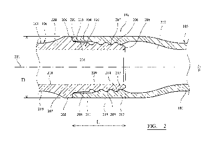
Figure 2 is a cross section through the male and female coupling of the drill
string of figure
1;
Figure 3 is a graph of the energy of an incident shock wave at the coupling
and the energy
transmitted through the coupling to illustrate the transmission efficiency of
the present
invention compared with a drill string having conventional threaded couplings;
Figure 4 is a graph of energy transmission efficiency through a drill string
having different
coupling configurations.
Detailed description of preferred embodiment of the invention
As will be appreciated a stress or shock wave that is transmitted through a
drill string from
the initial impact piston comprises a generally rectangular shape profile
having a
wavelength that is approximately twice the length of the piston and a wave
amplitude that
depends of the speed of the piston on impact and the relationship between the
cross
sectional area of the piston and the drill rod. Typically, the shock wave
loses a significant
percentage of its energy as it is transmitted through the coupling region of
the drill string.
Additionally, it is well established that differences in the cross sectional
area between the
CA 02922454 2016-02-25
WO 2015/032642 PCT/EP2014/067979
-7-
male and female threaded couplings contribute to the impedance mismatch in the
drill
system.
However, the subject invention provides an energy transmission efficient
coupling that
minimises the length of the impedance mismatch by minimising an axial length
of the
overlap region between the threaded male and female coupling ends of the drill
string rods.
Referring to figure 1, a drill string comprises a plurality of interconnected
drill string rods
100. Each rod 100 comprises a main length section 101 having a first end 105
and a
second end 106. An outside diameter of the main length section 101 increases
at each end
105, 106 to form a radially flared end coupling region 103, 104 respectively.
A part of
each coupling end 103, 104 comprises a threaded portion to allow the ends 103,
104 to
engage one another and form a secure threaded coupling 102 to interconnect a
plurality of
rods 100 to form the drill string.
Figure 2 illustrates the coupling region 102 of figure 1 in more detail. In
particular, male
end 103 projects axially from main section end 106. An annular shoulder 203
projects
radially from end 106 such that a diameter of an outer surface 202 of shoulder
203 is
greater than a diameter of main section 101 at external surface 219. The
radially outermost
region of shoulder 203 is bordered at a first side by a concave tapered
surface 220 and at a
second side by an annular abutment surface 201 aligned perpendicular to a
longitudinal
axis 221 extending through the rods 100. Male end 103 comprises a shank 204
aligned
substantially parallel with axis 221 and having an outer surface 215 aligned
substantially
parallel to axis 221. Shank 204 is terminated at its endmost region by a
threaded section
indicated generally by reference 205. In particular, section 205 corresponds
approximately
in shape and configuration to shank 204 but comprises external facing threads
extending
axially between an annular end surface 208 (of male coupling 103) and shank
204.
According to the specific implementation, the thread is formed from two
helices having 1.5
helical turns between shank 204 and end surface 208. An external shape profile
of
threaded section 205 therefore comprises a series of ridges 206 and troughs
207 when the
male end is viewed externally from one side for example. According to the
specific
implementation, the outside diameter of the threaded section 205,
corresponding to an axial
CA 02922454 2016-02-25
WO 2015/032642 PCT/EP2014/067979
-8-
and radial position of the peak of each ridge 206 is approximately equal to an
outside
diameter of main length section 101. Additionally, an outside diameter of
shank surface
215 is approximately equal to the outside diameter of the axial and radial
position
corresponding to each ridge 206. Male end 103 is hollow so as to comprise an
internal
surface 209 that is aligned parallel or coaxially with an internal surface 210
of main length
section 101.
Female end 104 comprises a generally hollow sleeve-like configuration that is
generally
flared radially outward relative to main length section 101 and is coupled to
section 101
via a radially tapered region 217. Sleeve 104 comprises an external surface
218 and a
corresponding internal surface 216. An axially endmost region 211 of sleeve
104
comprises internal surface 216 aligned substantially parallel with axis 221. A
threaded
region 212 is positioned axially between endmost region 211 and flared region
217 and
comprises threads formed at internal surface 216. To correspond to the threads
of the male
end 103, the threads of the female end 104 also comprise 1.5 complete helical
turns to
define a helically extending ridge 213 and trough 214, with ridge 213
projecting radially
inward towards the trough 207 of male end 103.
Male end 103 is fully engaged within the sleeve-like configuration of the
female end 104
when an endmost annular surface 200 of end region 211 abuts against the
annular abutment
surface 201 at the side of shoulder 203. The present implementation is
therefore described
by way of example with reference to a 'shoulder contact' configuration.
However, and as
will be appreciated, the present invention may be equally implemented in a
'bottom
contact' configuration in which male end surface 208 would abut against a
cooperating
abutment surface provided at a part of flared region 217. As indicated, the
subject
invention comprises a coupling region 102 that is optimised to minimise the
length of any
impedance mismatch between the coupled rods 100. That is, a length L that
represents the
axial length of the overlap between the male end 103 and the female end 104 is
maintained
to a minimum without compromising coupling strength and the ability of the
drill string to
withstand stresses and stress concentrations within the coupling region 102
resulting from
tensile and bending forces. In particular, male and female ends 103, 104 are
optimised
such that the axial length L, corresponding to the axial distance between male
end surface
CA 02922454 2016-02-25
WO 2015/032642 PCT/EP2014/067979
-9-
208 and female end surface 200, is less than an outside diameter D of the
female sleeve
104 corresponding to outer surface 218. Additionally, an axial length of the
male spigot
portion comprising a combined axial length of the shank 204 and threaded
section 205 is
less than outside diameter D of the sleeve 104. Such a configuration minimises
the mass
of male end 103 and accordingly the tensile stress created at the junction
between end 103
and shoulder 203 which would otherwise lead to breakage of the shank 204 away
from the
abutment surface 201. The present coupling is therefore configured to
withstand
significantly higher incident compressive shock waves resultant from higher
impact
amplitudes.
According to further specific implementations, each threaded sections 205, 212
may
comprise a single helix having between two to four complete helical turns
extending along
the full axial length of threaded sections 205, 212.
To illustrate the effectiveness of the subject invention to minimise impedance
mismatch
and accordingly reduce any transmission inefficiency through the multiple
coupling
regions 102, a comparison was undertaken between a coupling 102 of the subject
invention
and a conventional coupling in which the overlap distance L was greater. In
particular, and
according to the specific implementation, both sets of rods comprised a total
rod length of
3 m having a main length section 101 with an outside diameter of 110 mm and an
inner
diameter of 80 mm. The outside diameter D of each female coupling 104 was 140
mm.
The axial length of the male spigot 103 (including shank 204 and threaded
section 205)
was 125 mm. A corresponding axial length of a conventional test male spigot
was 190 mm
corresponding to distance L of figure 2. Accordingly, the 'overlap' region of
the two rod
types is represented by distance L of figure 2.
A simulation of the energy transmission was then undertaken using LS-DYNA mpp
R6.1.1
rev. 78769 in single precision and compiled for Linux CentOS 5.3.1. The
calculations
were undertaken by employing 12 Xenon64 CPUs. An inbuilt functionality was
used to
calculate the elastic and kinetic energies. These energies were then summed to
obtain the
total energy of the shock wave generated by the initial piston strike at the
region within the
main length section 101, representing incoming energy together with the
transmitted
CA 02922454 2016-02-25
WO 2015/032642 PCT/EP2014/067979
-10-
energy through the drill string after passing through a single coupling region
102. The
results of the simulation are illustrated in figure 3 where 300 corresponds to
the incoming
energy through section 101. The energy transmission profile for the subject
invention is
shown as 301 and the energy transmission efficiency of the conventional
coupling with a
longer overlap region L is shown as 302. As will be noted, the energy
efficiency of the
conventional coupling is approximately 96%. In contrast, the energy
transmission
efficiency of the subject invention is 98%. Figure 4 illustrates the
cumulative effect of
sequential coupling regions 102 on the total energy transmission efficiency.
In particular,
figure 4 illustrates the system efficiency for four different coupling
configurations in which
distance L is variable corresponding to a system with 99.5% efficiency 400;
99%
efficiency 401; 98% efficiency 402 (the subject invention) and 96% efficiency
403 (of the
simulated prior art coupling detailed above). As will be appreciated,
progression through
forty couplings provides an energy efficiency transmission increase of nearly
30%.