Note : Les descriptions sont présentées dans la langue officielle dans laquelle elles ont été soumises.
CA 02922549 2016-02-26
1
Sliding guide shoe for an elevator
The invention relates to a sliding guide shoe for an elevator for conveying
persons or
goods according to the preamble of claim 1.
Sliding guide shoes are frequently used for the guidance of elevator cars.
Elevator
installations in buildings have an elevator shaft which is usually vertical
and in which a
respective guide rail is arranged at each of mutually opposite shaft walls.
Sliding guide
shoes arranged at the elevator car contain inserts with slide surfaces which
slide with
small play along a guide rail. Sliding guide shoes in which the inserts are
formed as profile
members of U-shaped cross-section are known. By contrast to rolling guide
shoes, the
sliding guide shoe basically manages without movable parts. Since the inserts
wear in the
course of time, used or old slide inserts have to be exchanged.
A sliding guide shoe which is comparable in terms of category has become known
from
WO 2013/060583 A1. The sliding guide shoe comprises a two-part insert, which
is
inserted into a guide shoe housing, with a carrier element and one or more
slide elements.
The slide element can be pushed from a longitudinal side into a recess, which
extends in
longitudinal direction, in the carrier element. Since the recess is open in
the region of the
longitudinal side, the slide element has to be secured with the help of a
retaining part. If
the retaining element is screw-connected with the guide shoe housing, the
slide element is
clamped in place between a shoulder formed by the recess and the retaining
element.
It is an object of the present invention to create a sliding guide ,shoe of
the kind stated in
the introduction which is simple to handle. In particular, slide elements
shall be able to be
inserted in simple manner for the initial assembly of the sliding guide shoe
or old slide
elements shall be able to be rapidly and efficiently replaced for maintenance
or inspection
work.
According to the invention this object is fulfilled by a sliding guide shoe
with the features of
claim 1. The insert inserted or insertable into a guide shoe housing comprises
a slide
element facing the guide rail and a carrier element for carrying the slide
element. The two-
part insert thus has an inner insert part (slide element) and an outer insert
part (carrier
element). The carrier element with the recess is in that case designed in such
a way that
the slide element is introducible in longitudinal direction into the recess or
removable from
CA 02922549 2016-02-26
2
the sliding guide shoe so that after the end of the introduction process the
slide element is
captively fixed in the carrier element at least with respect to the
longitudinal direction. The
special design of the carrier element ensures that on introduction of the
slide element into
the receiving pocket the slide element can be secured in terms of position in
simple
manner in the carrier element solely as a consequence of the introduction
process and
thus, as it were, automatically and without use of further components.
The slide element can be fixed in the carrier element in particularly simple
manner if the
arrangement is designed in such a way that the slide element is detentable by
pushing in
insertion direction along the longitudinal direction into the carrier element.
The carrier element can comprise at least one movable or flexible securing
section for
securing or fixing the slide element inserted into the guide shoe housing,
which securing
section is movable outwardly or deformable for freeing an introduction
opening. The
freeing enables pushing of the slide element in insertion direction into the
recess of the
carrier element, which recess in the installed state extends along the
longitudinal direction.
The slide element can be removed again from the carrier element in the same
mode and
manner. For removal of the slide element, the mutually opposite securing
sections are
urged outwardly, whereby the detent locking is unlocked and the slide element
can be
withdrawn in longitudinal direction without resistance.
The securing section can be a flexible securing section which is preferably
integrally
formed at the carrier element and forms together with the carrier element a
component of
monolithic form. The carrier element can consist of, for example, a plastics
material. For
insertion of a slide element, the securing section is moved or urged outwardly
by hand or
by a tool from a rest setting to an open setting. The slide element can be
pushed in simple
manner into the now-open introduction opening. After or even during pushing-in
of the
slide element the securing section can be released. Thanks to the resilient
characteristics
of the plastics material the securing section returns to the original rest
setting without
further action.
The securing section could, however, also have a detent lug with a run-up
flank which co-
operates with the slide element and which is urged away when the slide element
is
inserted.
CA 02922549 2016-02-26
3
In a further form of embodiment the carrier element in the inserted state can
project
beyond the guide shoe housing by at least a section, whereby the securing
section is
exposed and can be urged away in simple manner from the outside.
If the carrier element at least in the inserted state is designed as a profile
member, which
is U-shaped in cross-section, with two limbs associated with the planoparallel
guide
surfaces of the guide areas of the guide rails and a profile member base
connecting the
limbs and associated with the front guide surface of the guide rail it can be
advantageous if
only the limbs project beyond the guide shoe housing. The profile member base
can thus
be constructed to be shortened relative to the profile member limbs. The
profile member
base is so dimensioned with respect to the longitudinal direction that when
the carrier
element is inserted into the guide shoe housing the profile member base is set
back or
approximately flush with the adjacent housing upper side of the guide shoe
housing.
In addition, it can be advantageous if the carrier element is locally weakened
in the region
of the securing section, whereby the securing section can be more easily moved
for
freeing the introduction opening. It is possible for, for example, a bending
line, about
which the securing section can be kinked, to be predetermined by the local
weakening.
With particular advantage the local weakening can be a recess extending
transversely to
the longitudinal direction. This recess can be arranged at the outer side of
the limb facing
the guide shoe. The recess ensures that, for example, in the case of use of a
plastics
material which is comparatively hard and thus has poor capability of bending
the securing
section nevertheless can be moved outwardly without excessive expenditure of
force and
without the risk of unintended material damage.
In a further form of embodiment a securing part for securing the securing
section in a rest
setting can be mountable or mounted at the guide shoe housing. The securing
section is
supported laterally outwardly by the securing part, whereby an outward
movement or a
deformation of the securing section is prevented.
A lubrication attachment can be fastened or fastenable at the longitudinal end
of the guide
shoe housing preferably in the region of the introduction opening
predetermined by the
securing sections and can in a given case additionally or alternatively to the
securing part
secure the securing section or sections in the rest setting. The lubrication
attachment has
CA 02922549 2016-02-26
=
= ..
4
a support structure with a recess for an oil insert. The oil insert can be
captively inserted,
preferably by light clamping, in the support structure. The oil insert can
consist of, for
example, a felt saturated or saturatable with oil. The felt element has inner
surfaces which
face the slide surfaces of the guide rail and which contact the slide surfaces
and thus the
guide rails are coated with a slight oil film as soon as the car travels.
The slide element can be formed by a U-shaped profile member, which can be of
rigid
form. The slide element can accordingly have two mutually opposite slide
surfaces and a
slide surface extending transversely thereto. In that case it can be a slide
element which
is formed as an integral and preferably monolithic component which
predetermines the
three afore-mentioned slide surfaces.
A further aspect of the invention could relate to a car for an elevator with
at least one
sliding guide shoe in the manner described in the forgoing.
Further advantages and individual features are evident from the following
description of an
embodiment and from the drawings, in which:
Figure 1 shows a simplified illustration of an elevator with an
elevator car guided by
way of sliding guide shoes at guide rails, in plan view,
Figure 2 shows a perspective view of a sliding guide shoe
according to the invention,
Figure 3 shows the sliding guide shoe of Figure 2 with a removed
slide element and
demounted securing part,
Figure 4 shows a sliding guide shoe, which is not yet assembled
to finished state, with
an opened carrier element for reception of the slide element,
Figure 5 shows the sliding guide shoe with partly pushed-in slide
element,
Figure 6 shows a variant of the sliding guide shoe according to
Figure 2 and
Figure 7 shows the sliding guide shoe of Figure 6 with demounted
lubrication
attachment.
CA 02922549 2016-02-26
Figure 1 shows an elevator, which is denoted overall by 1, with an elevator
car 2, which is
vertically guided between two guide rails 3 in an elevator shaft (not shown)
of a building to
be movable up and down. The travel direction of the car is indicated by an
arrow z. The
guide rail 3 is formed, for example, by a T profile member extending in z
direction. At least
one guide shoe 4 for guiding the car 2 at the guide rails 3 is arranged at the
elevator car 2
on each side. The guide shoe is a sliding guide shoe comprising an insert 6,
which is U-
shaped in cross-section and which embraces the guide rail 3 and extends - like
the guide
rails - in longitudinal direction z.
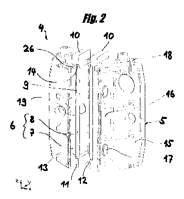
As evident from Figure 2, the sliding guide shoe 4 comprises a metallic guide
shoe
housing 5, which is of one-piece form in the present case, and an insert 6
inserted therein.
The insert 6 is of two-part construction and has, as inner insert part, a
slide element 8
facing the guide rail and, as outer insert part, a carrier element 7 for
carrying the slide
element. The outer insert part 7 consists of a material by which noise and
vibrations can
be damped during car travel. By contrast, the slide element 8 is of
comparatively stiff
form. The slide element has two planoparallel slide surfaces 19 and a slide
surface which
extends transversely to and connects these. The slide element 8 is made from a
plastics
material distinguished by a low coefficient of friction such as, for example,
PTFE or
UHMW-PE.
The guide shoe housing 5 consists of a plate-shaped base 15 and two support
walls 16,
which protrude vertically from the base and which form a channel-shaped
receptacle,
which extends in longitudinal direction z, for the insert 6. The carrier
element 7 has two
bearing pins 17 respectively on the outer sides, which pins engage in
corresponding cut-
outs in the support walls of the guide shoe housing 5, whereby the insert 6 is
fixed in the
guide shoe housing 5. The support element 7 is designed as a monolithic
component
which is U-shaped in cross-section. A resilient synthetic material (for
example TUR,
EPDM, NBR, NR), for example, is usable as material for the carrier element 7.
The
respective guide surfaces of the guide rail are acted on in sliding manner
with small play
by the slide surfaces of the slide element 8 during travel movement in z
direction. The
slide element 8 is received in a recess 9 formed to be complementary to the
slide element.
The recess 9 is formed in the carrier element 7 as a receiving pocket. The
carrier element
7 has a respective abutment for the slide element at each of the upper and
lower ends of
the recess 9. The lower (or upper depending on how the sliding guide shoe has
been
CA 02922549 2016-02-26
. .
= 6
mounted on the car) abutment, which is denoted by 13, is formed by a shoulder
which
downwardly bounds the recess. The slide element 8 is supported on the opposite
side at
a shoulder 14 which is a component of a detent connection described in more
detail in the
following. A securing section 10, thanks to which the slide element 8 is
captively fixed in
the carrier element 7, closes the recess upwardly (or downwardly).
The two mutually opposite securing sections 10 connected with the two limbs 11
of the
carrier element protrude at the longitudinal side beyond the guide shoe
housing 5. A
securing part 18 is screw-connected with the longitudinal end of the guide
shoe housing
for fixing and ensuring a secure seat. The securing sections 10 are supported
laterally at
the securing part 18, whereby the flexible securing sections 10 are prevented
from being
able to move outwardly.
In order that the slide element can be inserted, the securing part has to be
unscrewed and
removed. Figure 3 shows the guide shoe in this state. It is particularly
evident from Figure
3 that the recess 9 for receiving the slide element is designed as a receiving
pocket. The
recess, which extends over the entire width of the limbs 11 in z direction, is
closed with
respect to the longitudinal direction z on each side by the shoulders 13 and
14. For
opening, the securing sections 10 have to be urged outwardly. This can be
carried
manually or possibly with the help of a tool. The corresponding movement
direction is
indicated by the arrows a. Recesses 26 extending transversely to the
longitudinal
direction z produce a local weakening in the carrier element 7, whereby the
securing
sections 10 can be urged outwardly in simple manner and with little
expenditure of force.
However, particularly in the case of thin-walled carrier elements it would
also be
conceivable not to provide recesses or other local weakenings.
As Figure 4 shows, when the securing sections 10 are urged away an
introduction opening
arises, through which or into which the slide element can be pushed in simple
manner in e
direction into the upwardly open recess denoted by 9'. A bending edge about
which the
securing section 10 has been kinked is indicated by 26. However, a sharp kink
of that kind
is not usually present under actual conditions.
Figure 5 shows the sliding guide shoe during a pushing in process. Since the
slide
element 8 can also be withdrawn or inserted when the rest of the sliding guide
shoe
remains at the guide rail, substantial advantages arise for maintenance outlay
with respect
CA 02922549 2016-02-26
7
=
to time saving and manageability. The laborious and time-consuming demounting
of the
entire sliding guide shoe from the car can thus be eliminated. After
completion of the
pushing-in process, the securing sections 10 automatically return to the
original rest
position thereof due to the restoration capability of the material for the
carrier element, an
advantageous detent connection thus arising.
Instead of the simple securing part according to the present embodiment, in
the variant
according to Figure 6 a multi-part element is fastened to the guide shoe
housing 5. The
mentioned multi-part element 20 comprises an insert 22 which, for example,
consists of a
felt saturated with oil. This felt element 22 has inner surfaces which face
the slide
surfaces of the guide rail and which contact the slide surfaces. Through the
contacting
action by the felt element, the guide rails can be coated with a light oil
film as soon as the
car travels. The element, which is denoted in its entirely by 20, is therefore
termed
lubrication attachment in the following.
The lubrication attachment 20, which is attachable at the longitudinal end of
the guide
shoe housing, further consists of a support structure 21 which has a receiving
space 25
adapted to the oil insert. As evident from Figure 7, the oil insert 22 can be
inserted in f
direction into the receiving space 25 of the support structure 21. In the
present
embodiment the support structure 21 consists of two bent parts 27, 28 of metal
(for
example, steel). The bent parts 27, 28 can be placed together in such a way
that a
receiving space 25 is created, in which the oil insert is received or
receivable in sandwich-
like manner between the U-shaped area sections of the bent parts 27, 28. The
oil insert
22 is thus captively retained in the support structure 21, preferably lightly
clamped
between the planoparallel surface sections of the bent parts 27, 28. The bent
part 27 has
a recess 29, in which the securing section 10 is guided and which laterally
supports the
securing section 10 for securing purposes, adapted to the carrier element 7.
The
lubrication attachment 20 can be screw-connected in simple manner by means of
two
fastening screws to the guide shoe housing 5. When the oil insert 22 is dry
and thus
lubrication of the guide rails is no longer guaranteed, the oil inserts have
to be replaced by
oil-saturated felt elements. However, it would obviously also be conceivable
to freshly
saturate the dried-out insert 22 with a lubricating oil. By comparison with
known solutions,
which operate with oil reservoirs and feeds, this solution has the advantage
that on the
one hand it is favourable and simple in handling and on the other hand it is
ensured that
an excessive amount of oil is not applied to the guide rails. It has proved
that even in
CA 02922549 2016-02-26
8
different climatic conditions (for example conditions liable to change;
tropical conditions,
arctic conditions) satisfactory and substantially consistent lubricating
results , can be
achieved. Other materials able to accept lubricating oils would obviously also
be
conceivable instead of a felt part as oil insert 22. For example, foam
materials of synthetic
or animal material are conceivable.