Note : Les descriptions sont présentées dans la langue officielle dans laquelle elles ont été soumises.
CA 02924116 2016-03-11
WO 2015/043730 PCT/EP2014/002524
MOTORIZATION GROUP OF REELS IN A MACHINE FOR WINDING PLASTIC
FILM
The present invention relates to a motorization group
of reels in a machine for winding plastic film onto bobbins.
In the field of machines for winding plastic film onto
bobbins, reels provided with spindles are envisaged, which
effect the winding of plastic film onto the final desired
bobbins.
For this purpose, motors are envisaged, for moving the
single spindle of the single reel, capable of operating
successfully without any problems in the formation of the
bobbins thus obtained.
In these winding machines, the necessity of effecting
extremely rapid bobbin-change cycles leads to the need for
having equally rapid change sequences. During these
sequences, the spindle of the reel, i.e. the bobbin being
formed on the same, loses contact with the contact cylinder,
thus creating so-called "air" winding.
This entails the necessity of having a motorization
connected directly to the spindle of the reel in question,
by means of a frequency controlled motor. Furthermore, the
same configuration of the winding group (of the "revolver"
type, typically used specifically due to the necessity of
having extremely rapid change sequences) imposes the
1
CA 02924116 2016-03-11
WO 2015/043730 PCT/EP2014/002524
relative rotation of the reel spindle with respect to a
rotation centre outside the same.
This could lead to the necessity of having the motors
connected to the single spindles of the single reels, also
rotating around said rotation centre.
This kind of embodiment implies the assembly of all the
control parts of the above-mentioned motors (frequency
variators, control CPUs, remote switches, etc..) on a
rotating plate assembled in axis with the rotation centre
outside the reels. This arrangement leads to the necessity
of using rotating joints (typically of the mercury type)
for conveying signals and power supply to these components,
and also to the motors themselves.
This configuration, especially in the presence of
extremely high velocities, as in this case (up to 800 m/min
and over), consequently entails the extremely high risk of
having significant and damaging vibrations.
These vibrations are caused by an inevitable
unbalancing of the system. A system such as this, in fact,
on the one hand has a considerable constant weight
represented by the above-mentioned components, inevitably
assembled cantilevered with respect to the supporting
structure of the machine. On the other hand, the system has
a second equally considerable weight but extremely variable
during the operational phases, and also unbalanced with
2
respect to the single spindles of the reels, represented by
the bobbins being wound.
Therefore, it would be very useful and advantageous to
solve the above-mentioned drawbacks of the known art, in an
extremely simple, economical and particular functional manner.
More particularly, and according to one aspect of the
present invention, an objective is to provide a machine for
winding plastic film onto bobbins comprising a motorization
group of reels, wherein spindles are positioned on a rotating
plate around a central shaft constrained to a frame of the
machine, a motor being provided for each of said spindles,
each of said motors being constrained to said frame and being
connected to each of said spindles by means of a belt
transmission which comprises a central deflector unit, belts
connecting said central deflector unit, on one side, to said
spindles and on the other, to said motors, wherein said belts
are toothed belts and wherein said rotating plate carries
three spindles positioned at 120 with respect to each other,
characterized in that said central deflector unit is
aligned with a central shaft outside said frame and comprises
three hollow coaxial shafts positioned on an extension of said
central shaft with interposition of end bearings so as to
allow a reciprocal independent rotation with respect to the
extension, said three hollow coaxial shafts each carrying a
pair of toothed pulleys constrained to ends of said shafts
which interact with said belts for rotating said spindles.
Other possible aspect(s), objective(s), embodiment(s),
variant(s) and/or advantage(s) of the present invention, all
3
Date Recue/Date Received 2020-09-17
being preferred and/or optional, are briefly summarized
hereinbelow.
For example, a further objective of the present invention
is to provide a motorization group of reels in a winding
machine of plastic film onto bobbins which does not have heavy
cantilevered components which rotate with respect to the
frame.
Yet another objective of the present invention is to
provide a motorization group of reels in a winding machine of
plastic film onto bobbins which eliminates the vibrations
specifically due to the varied arrangement of weights in the
rotating parts.
In view of the above objectives, according to the present
invention, a motorization group of reels in a winding machine
of plastic film onto bobbins has been conceived, having the
characteristics specified in the present patent specification.
The structural and functional characteristics of the
present invention and its advantages with respect to the known
art will appear even more evident from the following
description, referring to the enclosed drawings which show
3a
Date Recue/Date Received 2020-09-17
CA 02924116 2016-03-11
WO 2015/043730
PCT/EP2014/002524
an embodiment of a motorization group of reels in a winding
machine of plastic film onto bobbins produced according to
the invention.
In the drawings:
figure 1 is a schematic raised side view showing
part of a winding machine comprising a motorization group
of reels in a winding machine of plastic film onto bobbins
produced according to the invention;
figure 2 is an enlarged view of some parts of
figure 1, partially sectioned for a better understanding,
which shows the connection of a single motor to the
respective reel and spindle;
figure 3 is a side view of the motorization group
of reels in a winding machine of plastic film onto bobbins
produced according to the invention;
figure 4 is an enlarged sectioned detail of the
central deflector unit with three coaxial shafts, forming
part of the motorization group of the present invention.
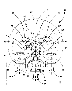
With reference first of all to figure 1, this
illustrates a schematic raised side view showing part of a
winding machine of plastic film onto bobbins, mainly in the
area comprising a motorization group of reels 90 produced
according to the invention.
4
CA 02924116 2016-03-11
WO 2015/043730 PCT/EP2014/002524
The motorization group of reels 90 is arranged outside
the structure consisting of two vertical uprights 12, 13
which form the shoulders of a frame of the winding machine.
The first upright 12 carries cantilevered on a rotating
supporting plate 14, a central shaft 15, supported, at the
other end, by the second upright 13.
The plate 14, rotating around the central shaft 15,
also carries three spindles 16, 17 and 18, arranged at 120
with respect to each other, which complete the winding
reel.
This system is repeated for as many times as the total
number of reels (3 in the example, but which can generally
vary from 2 to 4).
The figures show how, in the example illustrated of
three reels 16, 17 and 18, there are three motors 86, 86'
and 86" for the independent rotational movement of the
spindles 16, 17 and 18. The three motors 86, 86' and 86"
are fixed to the frame of the machine, in the example on
brackets 87 of the first upright 12.
The present invention, in fact, proposes a "static"
solution specifically for preventing the vibrations and
drawbacks mentioned above, i.e. with the assembly of the
motors of the reels and relative command and control
components in a fixed position, firmly anchored to the
supporting structure of the machine.
5
CA 02924116 2016-03-11
WO 2015/043730 PCT/EP2014/002524
This can be effected thanks to the new and original
solution which envisages a central deflector unit 83,
aligned with the central shaft 15, for transmitting the
motion coming from the various motors 86, 86' and 86",
through belts to all of the spindles 16, 17 and 18 of the
reels present.
Figure 2 very clearly illustrates a single reel with
its spindle 16 and its functioning principle with a part
of the arrangement of the motorization group of the reels
90 produced according to the invention, and the central
deflector unit 83 mentioned above.
In the example, the motor 86 effects the rotation
movement of the spindle 16 of this reel. A pulley 88 is in
fact inserted onto a shaft of the motor 86 and controls a
toothed belt 89.
This pulley 88 inserted onto the shaft of the motor 86,
is, in turn, connected by means of the toothed belt 89 to
a pulley 91 assembled in axis on an extension 92 of the
shaft 15. More specifically, there is presence of the
central deflector unit 83 aligned with the central shaft
15 which, as already mentioned, forms the rotation centre
of the rotating plate 14 carrying the spindles of the reels,
outside the structure of the machine, or the first upright
12.
' In particular, the pulley 91 is inserted integrally
6
CA 02924116 2016-03-11
WO 2015/043730
PCT/EP2014/002524
onto a shaft 93 of the central deflector unit 83. A further
pulley 94 is also inserted onto said shaft 93 of the central
deflector unit 83 and, in turn, controls an end of a toothed
belt 95 which is wound, at the other end, onto a pulley 96
inserted in an extension of the spindle 16 of the above-
mentioned reel.
This part of the arrangement of the motorization group
of reels 90 and the deflector unit mentioned above according
to the invention, is repeated for as many times as the
total number of reels (typically three, as illustrated, but
generally varying from 2 to 4) to form the complete
motorization group of reels.
In the embodiment shown, the central deflector unit 83
has three coaxial shafts as is clearly evident in figure
4, which is an enlarged sectioned detail.
In the figures, reference numbers have been used,
without an index or with an index or two
", etc.. for
the various spindles 16, 17 and 18 described and
illustrated.
Said central deflector unit 83, with three coaxial
shafts, allows an easy rotation of the rotating plate 14
carrying the spindles 16, 17 and 18 without any problem for
the various connecting belts 89, 89', 89" and 95, 95',
95" between the motors 86, 86', 86", fixed to the shoulder
7
CA 02924116 2016-03-11
WO 2015/043730 PCT/EP2014/002524
12 of the frame, and the reels 16, 17 and 18 which, on the
contrary, are present on the rotating plate 14.
The coaxial shafts 93, 93' and 93" are hollow and are -
positioned on the extension 92 of the central shaft 15 with
the interpositioning of end bearings 99, 99' and 99", so
as to allow a reciprocal independent rotation with respect
to the extension 92.
Figure 4 shows how this central deflector unit 83 is
produced, by arranging the two toothed end pulleys 91 and
94 which cooperate with the transmission of the motion
coming from the first motor 86, fixed by means of bolts
100, coaxially directed, at the opposite ends of the first
shaft 93. The first shaft 93 has a smaller external diameter
than the other shafts and an internal diameter slightly
larger than the external diameter of the extension 92. End
bearings 99 allow an easy rotation of the pulleys 91 and
94 and hollow shaft 93 during the rotation of the motor 86.
The second shaft 93', also hollow, supported by end bearings
99' which allow it to rotate, is positioned above an
intermediate area of the first shaft 93. This second hollow
shaft 93' carries, at opposite ends, fixed by means of
bolts 100', pulleys 91' and 94' which transmit the rotation
imparted by the second motor 86'.
Finally, the third shaft 93" is hollow and has a larger
internal diameter, which is such as to be able to rotate
CA 02924116 2016-03-11
WO 2015/043730 PCT/EP2014/002524
on the outer surface of the second shaft 93'. This third
shaft 93" also carries, fixed to opposite ends by bolts
100", pulleys 91" and 94" which allow the rotation imparted
by the third motor 86" to be transmitted.
This arrangement with three coaxial shafts, forming
part of the motorization group of the present invention,
is cantilevered towards the outside of the upright 12 of
the frame, and allows an easy transmission of the motion.
As illustrated, the bearings 99, 99', and 99" are housed
in shaped cavities 101, situated in the body of the various
pulleys 91 and 94, 91' and 94', and 91" and 94" positioned
consecutively on the hollow shafts 93, 93' and 93".
Figure 3 clearly shows the example relating to an
embodiment with three reels and relative independent
spindles (also mentioned above), each equipped with and
characterized by the elements previously described and
listed.
In particular, belt-tensioning devices 97 (or "guide
pulleys") are represented in this figure 3, suitable for
guaranteeing the correct tensioning of the toothed
transmission belt between the pulleys of the central
deflector unit 83 with coaxial shafts and the pulleys
inserted onto the spindles 16, 17 and 18. These belt-
tensioning devices also serve to recover the clearances
which are inevitably formed when elements are assembled,
9
CA 02924116 2016-03-11
WO 2015/043730
PCT/EP2014/002524
due to normal construction tolerances or which can be
generated by the consumption of the transmission components
involved in the system described.
Analogously, for the toothed transmission belts
positioned between the pulleys of the central deflector
unit 83 with coaxial shafts and the pulleys inserted on the
motors 86, 86', 86", registration devices 98 can be
envisaged, for example screws, also shown in figure 3.
In this way, for example, the central deflector unit
83 with coaxial shafts, also envisages, in addition to the
shaft 93 with a larger diameter, further shafts 93' and
93", coaxial to the same and having a smaller diameter, in
axis on the extension 92 of the shaft 15.
In this way, the shaft 93' also carries two pulleys 91'
and 94' inserted for the transmission of the motion by
, means of belts 89' and 95', for example to the spindle 17
driven by the motor 86'.
This arrangement is also repeated for the spindle 18
on which a pulley 96" is inserted, which receives the motion
from the belt 95", in turn driven by the pulley 94"
positioned on the shaft 93". This shaft 93" carries another
inserted pulley 91", driven in rotation by a toothed belt
89' controlled by a pulley 88', directly inserted on a
shaft of the motor 86".
CA 02924116 2016-03-11
WO 2015/043730
PCT/EP2014/002524
According to the present invention, therefore, the
driving motors of the spindles of the reels are fixed to
the frame and this arrangement prevents the creation of any
vibration. No relevant rotating masses are in fact present
with a variation in the position of the spindles of the
reels.
The winding machine is consequently well balanced and
functional also with a variation in the rotating weights
formed by the variable size of the bobbins of film being
wound.
The objective mentioned at the preamble of the
description has therefore been achieved.
The forms of the structure for producing a group of the
invention, as also the materials and assembly modes, can
obviously differ from those shown for purely illustrative
and non-limiting purposes, in the drawings.
The protection scope of the invention is therefore
delimited by the enclosed claims.
11