Note : Les descriptions sont présentées dans la langue officielle dans laquelle elles ont été soumises.
CA 02924173 2016-03-17
278482
TRACE GAS MEASUREMENT APPARATUS
FOR ELECTRICAL EQUIPMENT
I. TECHNICAL FIELD
[0001] The technical field relates generally to trace gas measurement
apparatus. In
particularly, the present invention relates to trace gas measurement apparatus
for measuring
and analyzing trace gases in electrical equipment (e.g., a transformer).
BACKGROUND
[0002] Trace gas in electrical equipment is typically generated from
electrical
insulating oil used in electrical equipment, which generates and distributes
electrical
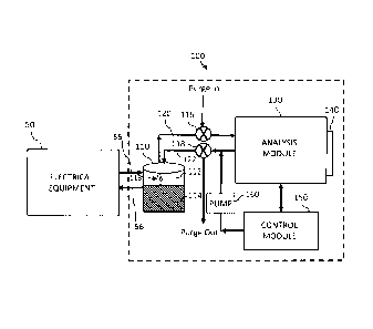
power. Some examples of electrical equipment include transformers, tap-
changers and
circuit breakers. When a fault occurs within the electrical equipment a trace
gas (i.e., a
fault gas) may be generated in the electrical insulating oil. Therefore, trace
gas
measurements are used to provide an operational and health status of the
electrical
equipment.
[0003] For example, in a transformer, when faults e.g., arcing and
overheating occur,
gases such as methane and carbon dioxide or carbon monoxide are present in the
insulating
oil of the transformer. Measurements of these trace gases can be used to
determine the
type and the severity of the faults which occur in the electrical equipment. A
measurement
device such as a photo-acoustic spectroscopy are typically used to obtain
trace gas
measurements where small vibrations of the molecules in trace gases are
generated when
subjected to a particular infrared (IR) frequencies of light, however external
vibrations of
measurement device can interfere with the measurement process.
SUMMARY OF THE EMBODIMENTS
[0004] The various embodiments of the present disclosure are configured to
provide
trace gas measurement apparatus which distinguishes between internal
vibrations of the
1
CA 02924173 2016-03-17
278482
trace gases and external vibrations of the measurement apparatus, to
efficiently measure
trace gases in electrical insulating oil of electrical equipment.
[0005] In one exemplary embodiment, a trace gas measurement apparatus is
provided.
The trace gas measurement apparatus includes a sample cell corresponding and
connectable to the electrical equipment and comprising a head space and
configured to
collect an oil sample from the electrical equipment. The trace gas measurement
apparatus
also includes an analysis module in communication with the sample cell, having
an analysis
chamber that includes a first measuring device at a first side thereof and a
second measuring
device disposed at a second side thereof at an axis that is substantially
perpendicular to the
first measuring device, and configured to measure and analyze trace gases from
an oil
sample received from the head space within the sample cell.
[0006] In one exemplary embodiment, a method is provided. The method
includes
receiving trace gases within the gas cell of the analysis chamber, from a
sample cell in
communication with the electrical equipment; applying infrared signals to
excite the trace
gases and generating pressure waves; detecting amplitudes from the pressure
waves using
a first measuring device in communication with the gas cell; and detecting
signals resulting
from external vibrations via a second measuring device positioned along an
axis that is
substantially perpendicular to the membrane surface of the first measuring
device.
[0007] In another exemplary embodiment, a method is provided. The method
includes
receiving trace gases within the trace gas cell of an analysis chamber, from a
sample cell
in communication with the electrical equipment; detecting signals from a first
measuring
device disposed at a first side of the analysis chamber and the second
measuring device at
a second side of the analysis chamber that is substantially perpendicular to
the membrane
surface of the first side; balancing the signals prior to performing trace gas
measurement
operation; applying infrared signals to excite the trace gases and generating
pressure waves;
detecting amplitudes from the pressure waves using a first measuring device in
communication with the gas cell; and detecting signals resulting from external
vibrations
2
CA 02924173 2016-03-17
278482
via a second measuring device positioned along an axis that is substantially
perpendicular
to that of the membrane surface of the first measuring device.
[0008] The foregoing has broadly outlined some of the aspects and features
of various
embodiments, which should be construed to be merely illustrative of various
potential
applications of the disclosure. Other beneficial results can be obtained by
applying the
disclosed information in a different manner or by combining various aspects of
the
disclosed embodiments. Accordingly, other aspects and a more comprehensive
understanding may be obtained by referring to the detailed description of the
exemplary
embodiments taken in conjunction with the accompanying drawings, in addition
to the
scope defined by the claims.
IV. DESCRIPTION OF THE DRAWINGS
[0009] FIG. 1 is a block diagram illustrating a trace gas measurement
apparatus that
can be implemented within one or more embodiments of the present invention.
[0010] FIG. 2 is a block diagram of an analysis module of the trace gas
measurement
apparatus shown in FIG. 1 that can be implemented within one or more
embodiments of
the present invention.
[0011] FIG. 3 is a flow diagram illustrating an exemplary method of
implementing an
embodiment of the present invention.
[0012] FIG. 4 is a flow diagram illustrating an exemplary method of
implementing an
alternative embodiment of the present invention.
[0013] The drawings are only for purposes of illustrating preferred
embodiments and
are not to be construed as limiting the disclosure. Given the following
enabling description
of the drawings, the novel aspects of the present disclosure should become
evident to a
person of ordinary skill in the art. This detailed description uses numerical
and letter
designations to refer to features in the drawings. Like or similar
designations in the
3
CA 02924173 2016-03-17
278482
drawings and description have been used to refer to like or similar parts of
embodiments
of the invention.
V. DETAILED DESCRIPTION OF THE EMBODIMENTS
[0014] As required, detailed embodiments are disclosed herein. It must be
understood
that the disclosed embodiments are merely exemplary of various and alternative
forms. As
used herein, the word "exemplary" is used expansively to refer to embodiments
that serve
as illustrations, specimens, models, or patterns. The figures are not
necessarily to scale and
some features may be exaggerated or minimized to show details of particular
components.
In other instances, well-known components, systems, materials, or methods that
are known
to those having ordinary skill in the art have not been described in detail in
order to avoid
obscuring the present disclosure. Therefore, specific structural and
functional details
disclosed herein are not to be interpreted as limiting, but merely as a basis
for the claims
and as a representative basis for teaching one skilled in the art.
[0015] Exemplary embodiments of the present invention provides a trace gas
measurement apparatus for performing dissolved gas analysis (DGA) on
electrical
insulating oil flowing within electrical equipment (e.g., transformers,
circuit breakers, or
tap changers). The trace gas measurement apparatus may be implemented within a
portable
gas analyzer (PGA). The DGA process is used to determine the health (e.g., the
occurrence
any faults or failure) of the electrical equipment and the current state of
operation thereof.
The trace gas measurement apparatus effectively performs the DGA testing by
eliminating
vibration signals received externally from an analysis module of the trace gas
measurement
apparatus by employing an accelerometer to detect the external vibrations. The
signals
obtained from the external vibrations by the accelerometer are cancelled from
the signals
obtained from the internal vibrations resulting from pressure wave signals
received at a
microphone of the trace gas measurement apparatus.
[0016] FIG. 1 is a block diagram illustrating a trace gas measurement
apparatus that
can be implemented within one or more embodiments of the present invention. As
shown
in FIG. 1, the trace gas measurement apparatus 100 is connectable to and
communicates
4
CA 02924173 2016-03-17
278482
directly with electrical equipment 50. This communication may be performed in
real-time,
on-line during operation of the electrical equipment 50. The trace gas
measurement
apparatus 100 may be disposed in direct contact with the electrical equipment
50 or in a
remote location while maintaining communication with the electrical equipment
50. The
present invention is not limited to the trace gas measurement apparatus 100
being disposed
in any particular location, the location may be any location suitable for the
purposes set
forth herein. Further, the present invention is not limited to the electrical
equipment
including any particular type or number of electrical equipment components
(e.g.,
transformers, tap changers, and/or circuit breakers), and may vary
accordingly.
[0017] The trace gas measurement apparatus 100 includes at least one sample
cell 110
corresponding to and connectable to the electrical equipment 50, and including
a head
space 112 and an oil sample 114. The sample cell 110 collects the oil sample
114 of
insulating oil flowing through the electrical equipment 50. The trace gas
measurement
apparatus 100 further includes a plurality of valves 116 and 118 within
respective forward
and return paths 120 and 122 connecting the sample cell 110 to an analysis
module 130 for
performing DGA. The present invention is not limited to using any particular
type of
control mechanism for stopping and starting of flow within the forward and
return paths
120 and 122, and may vary accordingly.
[0018] According to one or more embodiments, a first measuring device,
e.g., at least
one microphone 140, is disposed adjacent to the analysis module 130. Any type
of
transducer or sensor for converting sound into electrical signals may be
implement within
the present invention suitable for the purpose set forth herein. According to
some
embodiments, a single microphone 140 is provided, however, the present
invention is not
limited hereto. The present invention is not limited to use of a microphone,
other devices
may be employed such as a laser reflected by a thin reflective membrane, a
strain gauge
attached to a thin membrane, or an inertially small accelerometer attached to
a thin
membrane.
CA 02924173 2016-03-17
278482
[0019] A control module 150 is also provided in communication with the
analysis
module 130, and a circulation pump 160 is connected between the control module
150 and
the forward and/or return paths 120 and 122.
[0020] Further as shown, the oil sample 114 in the sample cell 110 is
supplied via a
forward line 55 from the electrical equipment 50 to the sample cell 110 during
operation
of the trace gas measurement apparatus 100. And the oil may be returned to the
electrical
equipment 50 via the return line 56, if desired. The oil sample 114 resides in
the sample
cell for a predetermined period of time during which a measurement and
analysis operation
is to be performed. Although a single sample cell 110 is provided, a plurality
of sample
cells 110 may be provided to accommodate multiple electrical equipment
components as
needed. Alternatively, multiple electrical equipment components may be
connected to a
single sample cell 110.
[0021] Further in operation, the oil sample 114 which is drawn from the
electrical
equipment 50 is agitated by an agitator (not shown) to cause dissolved gases
(i.e., trace
gases) 113 to be released into the head space 112. When the valve 116 is
opened in a first
position, the trace gases 113 are transferred via the forward path 120 to the
analysis module
130 for performing analysis thereof.
[0022] Depending on the measurement operation being implemented, the return
valve
118 may be set to return trace gases 113 from the analysis module 130 back to
the sample
cell 110 (e.g., in a closed loop arrangement) or to cause the trace gases 113
from the
analysis module 130 to be purged out of the trace gas measurement apparatus
100 via the
valve 118 (e.g., in an open circuit arrangement). Additional details regarding
the
measurement operation will be discussed below with reference to Fig. 2.
[0023] According to one or more embodiments, the control module 150 which
includes
a microcontroller or microprocessor programmed with computer software for
performing
analysis of the gases 113 when supplied to the analysis module 130. The
control module
150 controls the operation of the analysis module 130 and the circulation pump
160. The
6
CA 02924173 2016-03-17
278482
control module 150 may be any type of computing device capable of performing
the
operations of the present invention.
[0024] The circulation pump 160 is disposed within the return path 122
and/or forward
path 120 for controlling the flow of fluid along the forward and return paths
120 and 122
between the electrical equipment to the analysis module 130. The present
invention is not
limited to the use of any particular type of pump device, and therefore any
pump device
suitable for the purposes set forth herein may be employed.
[0025] FIG. 2 is a block diagram of the analysis module 130 of the trace
gas
measurement apparatus 100. As shown in FIG. 2, the analysis module 130
comprises an
analysis chamber 131 housing all of the components of the analysis module 130.
The
analysis chamber 131 includes a trace gas cell 132, having input and output
lines and valves
133 and 134 for controlling the flow of trace gases 113 into the trace gas
cell 132 when
desired. The analysis chamber 131 further includes a photo-acoustic
spectrometer 200
comprising a filter selector 135, a strobe wheel 136, a broadband IR frequency
source 137
and a reflector 138. The microphone 140 is disposed at a surface of the
analysis chamber
131 and in communication with the trace gas cell 132 (as indicated by the
arrow).
[0026] According to an embodiment of the present invention, the analysis
module 130
further comprises a second measuring device 170, e.g., an accelerometer 170,
mounted
either directly on a surface 131a of the analysis chamber 131 via mounting
components
(e.g., bolts), at a manifold of the analysis module 130, or mounted indirectly
to the surface
131a of the analysis chamber 131 via another component (i.e., a printed
circuit board (PCB)
180) mounted to the surface. The accelerometer 170 is aligned so that the axis
thereof is
detecting acceleration.
[0027] According to one embodiment, the accelerometer 170 is aligned so
that the axis
its detecting is on the same axis as that which the microphone 140 is picking
up signals.
According to embodiments, the accelerometer 170 includes its main axis aligned
with the
deflection of the microphone's 140 membrane, adding on more detection axes
onto the
accelerometer 170 allows for less critical placement of the primary
accelerometer axis.
7
CA 02924173 2016-03-17
278482
[0028] During the measurement operation, the photo-acoustic spectrometer
200
performs infrared (IR) photo-acoustic spectroscopy. Within the spectrometer
200, the
broadband IR source 137 supplies IR light to be reflected via the reflector
138 in a direction
trace gas cell 132. The strobe wheel 136 directs the light reflected to pass
through a
sequence of optical filters 135a of the optical filter selector 135. Each
optical filter 135a
is arranged to pass IR light in a respective frequency band associated with a
particular target
trace gas 113 (e.g., methane), to direct radiation into the trace gas cell
132, via window
thereof, which contains a sample of trace gas 113 to be analyzed.
[0029] Each target trace gas 113 within the trace gas cell 132 would then
absorb energy
at its respective resonant frequency, causing a vibration/rotation in the
molecules of the
target trace gas 113. The absorbed energy is then released creating pressure
waves. The
trace gas cell 132 is formed of a cylindrical shape in a vertical direction,
for example
however it is not limited hereto and may vary according. The microphone 140 is
disposed
on a side 132a of the analysis module 130 to be in communication with the
trace gas cell
132 at a side 132a thereof.
[0030] The gas cell 132 is connected to the microphone 140 such that when
the trace
gases 113 in the gas cell 132 are contracting and expanding, pressure waves
therefrom are
directed towards the microphone 140. The microphone 140 detects the pressure
waves and
the amplitudes thereof are used to determine the quantity of the target trace
gases 113.
[0031] According to one or more embodiments, the accelerometer 170 is
disposed at
location on a side 131a of the analysis chamber 131. The axis of the
accelerometer 170 is
perpendicular to an axis of the microphone 140 located at another side 131b of
the analysis
chamber 131.
[0032] The accelerometer 170 is able to detect and monitor external
vibrations external
to the analysis module 130. These external vibrations may interfere with the
measurements
of the internal vibrations of the pressure waves generated within the trace
gas cell 132
during the measurement process. To avoid the interference, embodiments of the
present
invention employ the accelerometer 170. The accelerometer 170 continuously
monitors
8
CA 02924173 2016-03-17
278482
and detects the external vibrations and converts them to electrical signals to
be subtracted
from the electrical signals detected by the microphone 140, to thereby
determine the actual
measurement for the target gases as desired. The measurements are used to
determine the
health of the electrical equipment 50.
[0033] Further, the data associated with the external vibrations as
detected by the
accelerometer 170 may be used to determine any electrical components which
create
interference, e.g., noise during the measurement operation, and to perform
adjustments of
the electrical components as necessary to eliminate the interference. The
present invention
is not limited to the above-mentioned measurement method. A measurement method
according to other embodiments as illustrated in Fig. 4 and discussed below
may also be
implemented. The accelerometer 170 may be a 1-axis type mounted at a location
perpendicular to the axis of the microphone 140 as shown in FIG. 2 and
discussed above,
to prevent external interference with the internal vibrations resulting from
the pressure
waves detection performed by the microphone 140.
[0034] Alternatively, the accelerometer 170 is not limited to any
particular type, and
may be of a 2-axis or 3-axis type or any other type of accelerometer which is
suitable for
the purposes set forth herein. Thus, the accelerometer 170 is not limited to
being disposed
in any particular location along the analysis chamber 131. A 3-axis
accelerometer 170 is
able to resolve and work out the vibration experienced by the microphone's 140
membrane.
[0035] After measurements are taken, valves 116 and 118 are open for
performing a
flushing or purging period under the control of the control module 150, to
thereby obtain a
new trace gas sample (i.e., trace gases 113). The analysis module 130
comprises an inlet
valve 133 for isolating it from the forward flow path 120 and an outlet valve
134 for
isolating it from the return flow path 122. The valves 133 and 134 are open to
allow the
contents in the analysis module 130 to be flushed out by gases or liquid, such
as clean air
or purging fluid received via valve 116 from the "Purge In" flow path, flow
through the
gas cell 132 and out at the "Purge Out" flow path in the open circuit
arrangement.
9
CA 02924173 2016-03-17
278482
[0036] After the flushing period, the inlet and outlet valves 133 and 134
are closed and
the trace gas cell 132 may receive the new gas sample including trace gases
113 for
analysis.
[0037] Trace gas measurement methods performed in the analysis module 130
in
accordance with embodiments of the present invention will now be discussed
with
reference to FIGS. 3 and 4. FIG. 3 is a flow diagram illustrating an exemplary
method 300
of implementing an embodiment of the present invention. FIG. 4 is a flow
diagram
illustrating an exemplary method 400 of implementing an alternative embodiment
of the
present invention.
[0038] As shown in FIG. 3, at operation 305 in method 300, trace gases are
received
within the gas cell of the analysis chamber, from the sample cell in
communication with
the electrical equipment.
[0039] From operation 305, the process continues to operation 310 where IR
signals
are applied to excite the trace gases and generate pressure waves. At
operation 315,
amplitudes from the pressure waves are detected using a first measuring device
(e.g., a
microphone) in communication with the gas cell.
[0040] From operation 315, the process continues to operation 320 where
signals
resulting from external vibrations are detected via a second measuring device
(e.g., an
accelerometer) positioned along an axis that is substantially perpendicular to
that of the
first measuring device.
[0041] At operation 325, trace gas measurements are then performed by
cancelling
(i.e., subtracting) the signals from the external vibrations as detected by
the second
measuring device from the signals resulting from the internal vibrations as
detected by the
first measuring device.
[0042] FIG. 4 is a flow diagram illustrating an exemplary method 400 of
implementing
an alternative embodiment of the present invention. As shown in method 400, at
operation
CA 02924173 2016-03-17
278482
405, trace gases are received within the trace gas cell of the analysis
chamber, from the
sample cell in communication with the electrical equipment.
[0043] From operation 405, the process continues to operation 410 where
signals from
the first measuring device (i.e, the microphone) and the second measuring
device (i.e., the
accelerometer) are balanced prior to performing the measuring operation. The
balancing
operation may be performed by applying a gain, or multiplying via a
multiplier, to the
signal of the accelerometer so that when the trace gas cell is agitated and
not excited, the
two signals can be balanced. Thus, when the signals resulting from the
internal vibrations
are generated only the microphone responds thereto and not the accelerometer.
However,
in the event of external vibration, the accelerometer will read the external
vibration and
cancel it from the signals received at the microphone. Data collection of the
accelerometer
signal may be added for further assessment of the location of the external
vibration.
[0044] From operation 410, the process continues to operation 415, where
infrared (IR)
signals are applied to the trace gases within the gas cell. From operation
415, the process
continues to operation 420 where amplitudes from pressure waves in the gas
cell are
detected using the first measuring device (i.e., the microphone) in
communication with the
gas cell.
[0045] From operation 420, the process continues to operation 425 where
signals
resulting from external vibrations are detected via the second measuring
device (i.e., the
accelerometer) positioned along an axis that is substantially perpendicular to
the first
measuring device's membrane surface. Then at operation 430, trace gas
measurements are
then performed by cancelling (i.e., subtracting) the signals from the external
vibrations as
detected by the second measuring device from the signals resulting from the
internal
vibrations as detected by the first measuring device.
[0046] The measurement apparatus of the present invention may be used in an
on line
measurement type arrangement with electrical equipment such as a main
transformer
and/or tank changer. The measurement apparatus may further be implemented in
real-time
to determine the condition of the total electrical system (e.g., a transformer
system). These
11
CA 02924173 2016-03-17
278482
faults can be detected early, to minimize cost associated with unplanned
outages and any
electrical equipment failure.
[0047] While there
have been described herein what are considered to be preferred and
exemplary embodiments of the present invention, other modifications of these
embodiments falling within the scope of the invention described herein shall
be apparent
to those skilled in the art.
12