Note : Les descriptions sont présentées dans la langue officielle dans laquelle elles ont été soumises.
81795875
- 1 -
Description
Method for setting up a wastewater pumping station in a
wastewater shaft, and associated wastewater pumping station
The invention relates to a method for setting up a wastewater
pumping station in a wastewater shaft, according to which
method at least one solids collecting tank for wastewater which
is guided through the same and is loaded with solids, a liquid
collecting tank for the wastewater which has been rid of solids
and has been pretreated in the solids collecting tank and a
pump which is assigned to the solids collecting tank for
emptying the liquid collecting tank via the solids collecting
tank are produced as separate assemblies for the most part in
each case.
That is to say the solids collecting tank, the liquid
collecting tank and the pump are able to be produced as three
separate assemblies. It is also possible, however, to condense
for example the pump and the solids collecting tank to form one
assembly. Then, with the liquid collecting tank as a further
assembly, a total of two assemblies are realized.
Wastewater pumping stations are generally installed into a
wastewater shaft and are utilized to pump wastewater, which has
collected at the bottom of a wastewater storage chamber, to a
certain level. Further treatment is then effected in the
majority of cases in a wastewater treatment plant. Large pumps,
the efficiency of which, however, leaves a lot to be desired,
are frequently used in practice for this purpose.
A wastewater pumping station where solids are separated
from the conveying medium, as a rule the wastewater, is
employed in the case of the generic method according to
CA 2926541 2019-05-06
cp.029265412016-04-06
WO 2015/055749
PCT/EP2014/072177
EP 1 108 822 Al. Only once this has taken place does
the wastewater, which has been pretreated in such a
manner, enter a regularly used pump. The solids
collecting tank which is connected upstream of the pump
takes care of the described separation of the solids
from the wastewater. A separating screen, by means of
which ideally the solids are held back, is typically
provided in the interior of the solids collecting tank
for this purpose. As a
result, pretreated wastewater
leaves the solids collecting tank and can be
transferred into the liquid collecting tank which is
connected downstream of the solids collecting tank.
In the case of the wastewater pumping stations realized
in practice, the procedure is generally such that the
wastewater shaft, the solids collecting tank, the
liquid collecting tank and the pump are all
prefabricated and installed at the installation site.
This is because this purpose, EP 1 108 822 Al proposes
in one variant that the liquid collecting tank and the
wastewater shaft which receives the wastewater pumping
station are produced from plastics material, the shaft
bottom simultaneously forming the bottom of the liquid
collecting tank. Industrial prefabrication of the
entire wastewater pumping station is able to be
realized in this manner, which simplifies installation
on site.
However, wastewater shafts produced from plastics
material can often not cope with the static and dynamic
loads prevailing on site or cannot cope with them in
the long term. Wastewater shafts produced from concrete
are increasingly used in this context for this reason.
This implies production of the wastewater shaft prior
to installation of the actual wastewater pumping
station because the transport of wastewater shafts
produced from concrete is ultimately prohibited for
reasons of cost. In this context, EP 1 108 822 Al
cA020266412016-04-06
WO 2015/055749 -,3 -
PCT/EP2014/072177
already proposes that the solids collecting tank and
the liquid collecting tank can be realized as
assemblies which are separate from one another by
providing a modular construction unit.
Such separate assemblies provide advantages in
maintenance and construction because maintenance jobs
and also repair jobs can be performed separately from
one another on the aforementioned construction elements
in the wastewater shaft that is present. This has
proved its worth in principle.
However, the handling of the component parts for the
wastewater pumping station in particular during
transport over large distances requires improvement.
This is because individual component parts of the
wastewater pumping station such as, in particular, the
liquid collecting tank, are particularly bulky and
heavy. This is even more valid when, as in the further
prior art according to DE 33 33 883 Al, a tank, which
is used to receive a pump for a wastewater pumping
station, is produced from concrete. Factory-based
series production is to be made possible as a result.
However, the volumes and weights looked at are
exorbitant such that in practice it is not possible to
transport the known tanks over long distances. The
invention aims to create a remedy here.
The technical problem underlying the invention is to
develop further such a method for setting up a
wastewater pumping station in a wastewater shaft such
that a clear reduction in costs is seen in particular
for transport and at the same time the setting up of
new stations as well as the renovation of older
stations is made easily possible.
To solve said technical problem, a generic method for
setting up a wastewater pumping station in a wastewater
c.A029265412016-04-06
WO 2015/055749
PCT/EP2014/072177
shaft within the framework of the invention is
characterized in that at least the solids collecting
tank and the pump are prefabricated as a construction
unit and the relevant construction unit is combined
with the liquid collecting tank, which is already
present on site, in the course of the installation in
the wastewater shaft, which is also already present on
site.
Within the framework of the invention, the wastewater
pumping station is consciously separated into component
parts that are present on site and component parts that
are prefabricated by the manufacturer. In this case,
the component parts that are present on site include
not only the wastewater shaft, as has already been
publicized in practice and described in the prior art,
but also according to the invention said component
parts that are present on site also additionally
include the liquid collecting tank.
Obviously, it is also possible for several liquid
collecting tanks to be present in the wastewater shaft
or realized on site if required. In addition, it is
within the framework of the invention to combine, for
example, several construction units produced in each
case from the solids collecting tank and the pump with
a liquid collecting tank or even several of said liquid
collecting tanks as described. As a result, a parallel
operation of, for example, two construction units can
be realized in order to obtain, for example, increases
in pressure and/or quantities overall. Over and above
this, it is also possible on the part of the
manufacturer to combine, for example, one solids
collecting tank with two or more pumps and likewise
several solids collecting tanks with one pump to form
the prefabricated construction unit. In each case, the
transport costs are significantly reduced because the
liquid collecting tanks are typically designed to be
cA029265412016-04-06
WO 2015/055749
PCT/EP2014/072177
bulky and heavy and according to the invention are
already realized on site.
To this is added that possible problems with the
compressive strength of the liquid collecting tank or
also adaptations on site when installing the liquid
collecting tank are non-existent. Apart from this, the
investment costs are reduced or can be split in terms
of time and function. To this is added that, according
to the described method, it is possible both to
renovate existing installations and produce new
installations. This is because, to do this, all that is
necessary is to adapt the construction unit to the
liquid collecting tank.
As a result of the separation between the component
parts that are present on site and the component parts
that are prefabricated (by the manufacturer) when
realizing the wastewater pumping station according to
the invention, one or several interfaces have
ultimately to be worked with. It is provided here
within the framework of the invention that the
construction unit which is produced from at least the
solids collecting tank and the at least one pump, on
the one hand, and the liquid collecting tank, on the
other hand, are coupled together on site by means of at
least one interface. Said interface can be mounted in
or on a partition wall.
The partition wall addressed is arranged, as a rule, in
the wastewater shaft. The wastewater shaft is able to
be divided into a dry chamber and a wet chamber by
means of the partition wall. The construction unit
which is produced from the solids collecting tank and
the pump is typically placed in the dry chamber. In
contrast, the function of the wet chamber is for
receiving the liquid collecting tank that is provided
there.
CA 0265412,)16-04-
WO 2015/055749
PCT/EP2014/072177
As the construction unit which is produced from at
least the solids collecting tank and the pump is
designed in a particularly compact manner within the
framework of the invention, transport costs can be
reduced and, compared to the prior art, it is possible
to work with a clearly reduced transport volume. This
presupposes at the same time that the liquid collecting
tank is produced on site in the interior of the
wastewater shaft according to corresponding
requirements and in particular the interface between
the construction unit and the liquid collecting tank
fulfills and also is able to fulfill its function.
Effectively, in the simplest case said interface can be
a tube coupling, a flange adapter and, where
applicable, a feedthrough for the partition wall. This
is because, as a rule, the pump is connected to the
liquid collecting tank on the suction side by means of
the interface.
In this case, it is also possible over and above this
to pass an intake for the construction unit through the
liquid collecting tank. The wastewater to be pumped is
supplied to the solids collecting tank by means of said
intake. As, consequently, the intake is expediently
passed through the liquid collecting tank and also
through the partition wall in the interior of the
wastewater shaft, it is once again necessary to work
with an interface to the relevant solids collecting
tank at this location.
On account of said design, it is possible to design the
wastewater shaft in a more compact manner and with a
smaller shaft height than previously. This is because,
as a result of the smaller height of the intake which
is passed through the liquid collecting tank compared
to the prior art, where the intake is arranged above
the liquid collecting tank, the available volume in the
2016-04-06 2015/055749
PCT/E02014/072177
wastewater shaft is able to be utilized in an optimum
manner.
In addition, mounting and arranging the liquid
collecting tank directly in the wastewater shaft
provides the possibility of the installation height of
the construction unit which is produced from the solids
collecting tank and the pump being reduced further.
This is because it is possible to integrate a
connecting line from the pump to the solids collecting
tank and an outlet, which is realized as a by-pass,
into the solids collecting tank. The design, in this
case, may be comparable to that already described in WO
2010/025852 Al.
It is quite particularly preferred when the liquid
collecting tank is integrated into the wastewater shaft
on site. That is to say, in the case of the on-site
production of, on the one hand, the wastewater shaft
and, on the other hand, the liquid collecting tank, the
procedure is such that the liquid collecting tank is
designed as part of or a component part of the
wastewater shaft. In this context, it is recommended
that the liquid collecting tank and the wastewater
shaft are produced for the most part from uniform
materials.
Effectively, such a design corresponds for the most
part to the liquid collecting tank and the wastewater
shaft comprising several common walls. For example, the
liquid collecting tank can be defined in the interior
of the wastewater shaft by the already addressed
partition wall such that the liquid collecting tank
covers simply part of the floor of the wastewater
shaft. The liquid collecting tank is consequently
defined in the wastewater shaft as an open tub which is
able to be closed at the head end by means of a
removable cover.
81795875
- 8 -
In this way, the partition wall carries out its dividing
function so to speak in an automatic manner. This is because
the wet chamber is defined in the region of the liquid
collecting tank, whereas the dry chamber is available for the
arrangement of the construction unit on the other side of the
wet chamber and of the partition wall. That is to say, the
modular solids collecting tank and also the at least one pump,
both of which are consequently accessible in a particularly
simple manner for maintenance and cleaning purposes, are
situated in the dry chamber, even during operation.
The construction unit which is produced from at least the
solids collecting tank and the pump can be produced from
different materials. Metal, plastics material and even concrete
have proved possible here, combinations also being included.
Comparable materials can also be used for the wastewater shaft
and, where applicable, the liquid collecting tank. That is to
say, concrete, metal, plastics material or combinations can be
worked with in this case too. An object of the invention is
also a wastewater pumping station and is set up in a wastewater
shaft in particular according to the previously described
method.
A method for constructing or setting up a wastewater pumping
station in the wastewater shaft and an associated wastewater
pumping station, both of which provide particular advantages
with regard to costs and logistics, are described as a result.
This is because, as a result of the modular design of
individual component parts and of the separation into component
parts which are present on site and component parts which are
prefabricated (by the manufacturer), it is possible not only to
equip new plants in a corresponding manner but also the
renovation of older plants is successful in a particularly
advantageous manner. This is because, in this connection, it is
only a question of making the wastewater shaft available on
CA 2926541 2019-05-06
81795875
- 9 -
site in connection with the liquid collecting tank. In
addition, the at least one interface between the liquid
collecting tank and the at least one solids collecting tank has
to correspond to the requirements.
As a result of the liquid collecting tank being present on site
or being realized on site before the construction unit, which
is produced from the solids collecting tank and the pump, is
installed into the wastewater shaft, it is possible to pass the
intake for the construction unit through the liquid collecting
tank and also to realize it already on site. In this case,
another additional interface, to which the intake is connected,
is then necessary between the intake, on the one hand, and the
solids collecting tank on the other hand. Low intake heights
can be realized as a result and overall the wastewater pumping
station can be designed in a particularly compact manner and
the shaft height of the wastewater shaft can be reduced to a
minimum.
Another advantage to be named is that as a result of the
compact design, it is also possible to work with few individual
parts and small installation openings in the wastewater shaft,
which reduces the costs even further. At the same time, repair
and maintenance are simplified. These are the essential
advantages.
In some embodiments of the present invention there is provided,
a method for setting up a wastewater pumping station in a
wastewater shaft, according to which method at least one solids
collecting tank for wastewater which is guided through the same
and is loaded with solids, a liquid collecting tank for the
wastewater which has been rid of the solids and has been
pretreated in the solids collecting tank and a pump which is
assigned to the solids collecting tank for emptying the liquid
collecting tank via the solids collecting tank are produced as
CA 2926541 2019-05-06
81795875
- 9a -
separate assemblies, wherein at least the solids collecting tank
and the pump are prefabricated by a manufacturer or at a factory
as a construction unit and transported to an installation site
and the construction unit is combined with the liquid collecting
tank, which is already present on site at the installation site,
in the course of the installation in the wastewater shaft, which
is also already present on site, according to which method the
construction unit and the liquid collecting tank are coupled
together on site by means of at least one interface configured as
a tube coupling, the construction unit and the liquid collecting
tank are separated from one another in the wastewater shaft by a
partition wall and the partition wall divides the wastewater
shaft into a dry chamber with the construction unit and a wet
chamber with the liquid collecting tank, wherein the interface is
mounted in the partition wall.
The invention is explained in more detail below by way of a
drawing which only shows one exemplary embodiment and in which:
CA 2926541 2019-12-18
CA 02926541 2016-04-06
WO 2015/055749 - 10 -
PCT/EP2014/072177
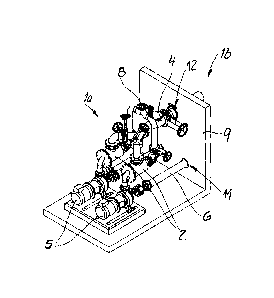
fig. 1 shows a perspective representation of the
wastewater pumping station according to the
invention,
fig. 2 shows a longitudinal section through fig. 1,
fig. 3 shows a top view of the object according to
figs. 1 and 2 and
figs. 4 to 6 show three different variants of the
wastewater pumping station according to figs. 1
to 3, installed in a wastewater shaft.
The figures show a wastewater pumping station which is
installed or can be installed in a wastewater shaft 1.
By way of the exemplary embodiments according to figs.
4 and 5, it can be seen that the wastewater shaft 1 may
be realized in a cylindrical manner (fig. 4) or also
can have the form of a cuboid (figs. 5 and 6). In all
the cases, the wastewater shaft 1 is produced from
concrete.
In its basic design, the wastewater pumping station has
a solids collecting tank 2. Two solids collecting tanks
2 which can be operated in an alternating manner, as is
described in principle in generic EP 1 108 822 Al, are
realized according to the exemplary embodiment. Solids
located in the wastewater are held back via the solids
collecting tank 2. This is because this purpose, the
wastewater which is loaded with solids is supplied via
an intake or an intake pipe 3 and a distributor 4 to
the two solids collecting tanks 2.
In the interior of the respective solids collecting
tank 2, a separating screen typically ensures that the
solids are held back and just pre-filtered wastewater
passes by means of a pump 5, which is assigned to the
solids collecting tank 2, and a suction pipe 6 finally
CA 029265412016-04-06
WO 2015/055749 - 11
PCT/EP2014/072177
into a liquid collecting tank 7. As soon as the pre-
filtered wastewater which is stored in the liquid
collecting tank 7 has reached a certain level, the pump
is activated and sucks in the pre-filtered wastewater
5 by means of the suction pipe 6. The pump 5 then
conducts the wastewater further via the solids
collecting tank 2, thereby entraining the solids there
to a pressure pipe 8, from where the wastewater pumped
in such a manner is supplied, for example, to a
wastewater treatment plant for further treatment. This
is known in principle, for which purpose reference is
made not only to EP 1 108 822 Al but also to WO
2010/025852 Al presented by the applicant.
The liquid collecting tank 7 and the pump or the two
pumps 5 are realized in each case as separately
produced assemblies. In addition, according to the
invention, at least the solids collecting tank 2 or the
two solids collecting tanks 2 and the pump 5 define a
prefabricated construction unit 2, 4, 5, 6, 8, to which
are also added in the exemplary embodiment and in a
non-restricting manner the distributor 4, the suction
pipe 6 and the pressure pipe 8. Said construction unit
2, 4, 5, 6, 8 can be seen in particular in fig. 1.
The relevant construction unit 2, 4, 5, 6, 8, which is
prefabricated for example by the manufacturer or at the
factory, is combined with the liquid collecting tank 7,
which is already present on site, during the course of
the installation of the construction unit 2, 4, 5, 6, 8
into the wastewater shaft 1, which is also already
present on site. In this case, the liquid collecting
tank 7 has been integrated on site into the wastewater
shaft 1.
This is because this purpose, the liquid collecting
tank 7 and the wastewater shaft 1 in the exemplary
embodiment are produced for the most part from uniform
cA029265412016-04-06
WO 2015/055749 - 12 -
PCT/EP2014/072177
materials. This is applicable at any rate to the two
realization variants according to figs. 4 and 5.
Effectively, the design there is such that the
wastewater shaft 1 is divided by means of a partition
wall 9 into a dry chamber la and a wet chamber lb. The
construction unit 2, 4, 5, 6, 8 is situated in the dry
chamber la.
In contrast, the wet chamber lb receives the liquid
collecting tank 7 provided there or the wet chamber lb
and the liquid collecting tank 7 coincide. This is
because, by means of the partition wall 9 (produced
from concrete), in the wastewater shaft 1 (also
produced from concrete) an upwardly open tub is defined
which can be closed by way of a removable cover 10
which is produced, for example, from concrete or metal,
such that overall as a result the closed liquid
collecting tank 7 is available.
The construction unit 2, 4, 5, 6, 8 and the liquid
collecting tank 7 are consequently separated from one
another in the wastewater shaft 1 by the partition wall
9. In addition, at least one interface 11, 12 is
provided in or on the said partition wail 9. The
interface 11, 12 is a tube connecting piece or a tube
coupling in conjunction with seals if necessary. In
addition, flanges and/or adapters can also be provided
as component parts of the interface 11, 12.
In the case of the exemplary embodiment according to
fig. 6, a partition wall 9 is not provided in the
interior of the wastewater shaft 1 at that location.
Rather, two (or also more) liquid collecting tanks 7,
which in this case are realized or can be realized in
each case as metal tanks, are situated in the interior
of the wastewater shaft 1. The two liquid collecting
tanks 7 can be connected together. In this respect,
once again alternating operation of the two
Q.,029265412016-04-06
WO 2015/055749 - .13 -
PCT/EP2014/072177
construction units 2, 4, 5, 6, 8 is just as possible as
already described with reference to the exemplary
embodiment according to figs. 4 and 5.
Within the framework of the exemplary embodiment, the
construction unit 2, 4, 5, 6, 8 and the liquid
collecting tank 7 are coupled together by means of the
interface 11, on site. That is to say the connection
between the construction unit 2, 4, 5, 6, 8 and the
liquid collecting tank 7 by means of the interface 11
is not effected until at the site of installation.
Namely when the construction unit 2, 4, 5, 6, 8 is
placed in the wastewater shaft 1 in order to become
coupled by means of the interface 11 with the liquid
collecting tank 7 which is already present on site.
The interface 12, in contrast, serves for coupling the
intake or the intake pipe 3 with the distributor 4 or
with the two solids collecting tanks 2. It is possible
in this way for the intake or the intake pipe 3 to be
able to be passed through the liquid collecting tank 7,
as is immediately clear in particular by way of figs. 2
and 5. As a result of this, it is possible to realize
the wastewater shaft 1 with only a small installation
height because the intake height to the construction
unit 2, 4, 5, 6, 8 is clearly reduced within the
framework of the invention compared to the prior art.
The construction unit 2, 4, 5, 6, 8 is produced overall
from metal, for example stainless steel. In principle,
however, plastics material can also be used as a
possible material within the framework of the
invention. In contrast, the wastewater shaft 1, and
with it for the most part the liquid collecting tank 7,
is produced overall from concrete. The removable cover
10 may consist of and be produced from metal.
CA 029265412016-04-06
WO 2015/055749 - .14 -,
PCT/EP2014/072177
As already explained in the introduction, the
construction unit 2, 4, 5, 6, 8 is prefabricated at the
factory or by the manufacturer and transported to the
installation site. Not only the wastewater shaft 1 is
situated on-site and according to the invention at the
installation site, but the liquid collecting tank 7 is
additionally also already present. This is because this
purpose, in the exemplary embodiment according to figs.
4 and 5, the partition wall 9 is established in the
wastewater shaft 1 and the liquid collecting tank 7,
which is defined in such a manner, is able to be closed
finally by means of the removable cover 10. This may be
effected in a pressure-tight manner. A pressure-tight
design can also be seen in the case of the two liquid
collecting tanks 7 according to fig. 6 which are also
already present on site in the wastewater shaft 1 and
are combined at the installation site with the
construction unit 2, 4, 5, 6, 8 which has been
prefabricated at the factory or by the manufacturer.