Sélection de la langue

Search

Sommaire du brevet 2927147 

Énoncé de désistement de responsabilité concernant l'information provenant de tiers

Une partie des informations de ce site Web a été fournie par des sources externes. Le gouvernement du Canada n'assume aucune responsabilité concernant la précision, l'actualité ou la fiabilité des informations fournies par les sources externes. Les utilisateurs qui désirent employer cette information devraient consulter directement la source des informations. Le contenu fourni par les sources externes n'est pas assujetti aux exigences sur les langues officielles, la protection des renseignements personnels et l'accessibilité.

Disponibilité de l'Abrégé et des Revendications

L'apparition de différences dans le texte et l'image des Revendications et de l'Abrégé dépend du moment auquel le document est publié. Les textes des Revendications et de l'Abrégé sont affichés :

  • lorsque la demande peut être examinée par le public;
  • lorsque le brevet est émis (délivrance).
(12) Brevet: (11) CA 2927147
(54) Titre français: ROULEAU DE BROYAGE DE BROYEUR
(54) Titre anglais: CRUSHING ROLL FOR A CRUSHER
Statut: Accordé et délivré
Données bibliographiques
(51) Classification internationale des brevets (CIB):
  • B02C 04/30 (2006.01)
(72) Inventeurs :
  • PETACK, BURKHARD (Allemagne)
  • SCHMIDT, MARKO (Allemagne)
  • EBENHAN, KARSTEN (Allemagne)
  • NEUFELDT, PATRICK (Allemagne)
(73) Titulaires :
  • TAKRAF GMBH
(71) Demandeurs :
  • TAKRAF GMBH (Allemagne)
(74) Agent: KIRBY EADES GALE BAKER
(74) Co-agent:
(45) Délivré: 2017-03-07
(22) Date de dépôt: 2016-04-14
(41) Mise à la disponibilité du public: 2016-10-17
Requête d'examen: 2016-04-14
Licence disponible: S.O.
Cédé au domaine public: S.O.
(25) Langue des documents déposés: Anglais

Traité de coopération en matière de brevets (PCT): Non

(30) Données de priorité de la demande:
Numéro de la demande Pays / territoire Date
10 2015 206 957.5 (Allemagne) 2015-04-17

Abrégés

Abrégé français

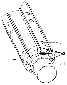
Rouleau de broyage conçu pour un broyeur de type à rouleaux et comportant un arbre doté dau moins une rainure suivant la direction axiale, sur sa surface latérale, afin de recevoir des éléments formés. Les éléments formés servent à retenir les enveloppes de broyage; à cette fin, les éléments formés créent une combinaison dentraînement qui enclenche les formes, avec la rainure de larbre, en direction radiale. Ici, une telle combinaison dentraînement en direction radiale correspond à des éléments qui bloquent le mouvement des éléments formés dans la direction radiale de larbre. Ainsi, il est possible dancrer les enveloppes de broyage dans les rainures au moyen des éléments formés. De façon avantageuse, les forces axiales des enveloppes de broyage peuvent également être transmises à larbre par les éléments formés dans les rainures. Lesdites forces peuvent donc être portées par larbre étant donné quune grande force de pression peut être exercée par la combinaison de lenveloppe de broyage et lélément formé, donnant ainsi lieu à une forte friction de retenue entre lélément moulé et larbre. À laide de larbre, il est possible déchanger individuellement les enveloppes de broyage lorsque le rouleau de broyage se trouve dans son état assemblé. La configuration est manifestement simple, et permet donc une fabrication économique.


Abrégé anglais

The crushing roll for a roll-type crusher has a shaft with at least one groove extending in the axial direction on its lateral surface, to receive formed elements. The formed elements serve to retain the crushing shells, for which purpose the formed elements form a form-interlockingly engaging combination with the groove in the shaft, in the radial direction. A form-interlockingly engaging combination in the radial direction is understood here to signify means of blocking of movement of the formed elements in the radial direction of the shaft. In this way, it is possible to anchor crushing shells in the grooves by means of the formed elements. Advantageously, also axial forces from the crushing shells can be transmitted to the shaft via the formed elements in the grooves, which forces can thereby be borne by the shaft, given that a high pressing force can be transmitted via the combination of crushing shell and formed element, resulting in high holding friction between molded element and shaft. By means of the shaft, it is possible to exchange crushing shells individually, in the assembled state of the crushing roll. Significantly, the configuration is easy and thereby economical to fabricate.

Revendications

Note : Les revendications sont présentées dans la langue officielle dans laquelle elles ont été soumises.


8
Claims:
1. A crushing roll for a roll-type crusher, comprised of a shaft with at
least one groove
extending in the axial direction, to receive formed elements which form a form-
interlockingly engaging combination with the groove of the shaft in the radial
direction,
wherein the formed elements have a threaded bore which is disposed such that
radially
directed screws can be retained by the groove, in order to attach the crushing
shells.
2. The crushing roll according to claim 1, wherein at least one groove is T-
shaped.
3. The crushing roll according to claim 1 or 2, wherein the shaft is
flattened in the
area of the grooves.
4. The crushing roll according to any one of claims 1 to 3, wherein at
least one groove
is open on the end sides of the shaft, so that the formed elements may be slid
in from the
end face of the shaft.
5. The crushing roll according to any one of claims 1 to 4, wherein the
shaft has
adjusting bolts or receiving means for adjusting bolts, on its lateral
surface.
6. The crushing roll according to any one of claims 1 to 5, wherein the
series of
crushing shells disposed adjacently in the axial direction are anchored in at
least two
grooves.
7. The crushing roll according to any one of claims 1 to 6, wherein the
movements of
the crushing shells in the tangential and axial direction of the shaft are
blocked by a
adjusting bolt and receiving means combination.

9
8 A roll-
type crusher comprised of at least one crushing roll according to any one of
claims 1 to 7.

Description

Note : Les descriptions sont présentées dans la langue officielle dans laquelle elles ont été soumises.


CA 02927147 2016-04-14
. ,
1
CRUSHING ROLL FOR A CRUSHER
The invention relates to a crushing roll for a roll-type crusher, and further
relates to
a roll-type crusher.
Roll-type crushers have at least two crushing rolls bearing crushing shells
with
crushing implements, on the surface of the rolls. The crushing shells and
implements
experience appreciable wear during the crushing operation, and accordingly it
is desirable
to be able to replace them in the simplest possible manner.
Toward this end, in EP 0110665 A2 it is proposed to combine the crushing
shells
with intermediate discs in a form-interlocking manner, with the intermediate
discs being
rotationally rigidly disposed on the shaft of the crusher. The manner of form-
interlocking
between the crushing shell and intermediate disc is arranged such that forces
which arise
during the crushing operation can be well accommodated. A drawback of this
solution is
that the crushing shells may be removed only laterally, in the axial
direction, and thus in
order to replace an interior crushing shell it is necessary to remove all
interposed crushing
shells.
Also, in US 2004/0251360 Al, a similar configuration employing intermediate
discs and crushing shells which latter form-interlockingly engage with the
intermediate
discs is proposed. Here the form-interlocking is obtained via an insert block
which enables
a given crushing shell to be accommodated independently from other crushing
shells. This
solution has the drawbacks that assembly costs are high, with a plurality of
components for
attaching the crushing shells, and it is highly likely that individual
crushing shells will
experience jamming, resulting in difficulty in removing the shells.

CA 02927147 2016-12-08
2
In EP 0110665 A2 [(same as above)], a shaft for a roll-type crusher is
disclosed
which has mutually parallel grooves on its surface which extend longitudinally
along
the roll. Crushing shells can be accommodated in these grooves, whereby the
shells
form-interlockingly engage the shaft in the radial direction. The crushing
implement
is accommodated via a bore in the crushing shell. The crushing shell is
anchored
directly, by attachment in the groove of the shaft. A drawback of this
solution is that
the crushing shells correspond to formed elements. As a result of this dual
function,
under conditions of high loads the crushing shell is subjected to increased
wear,
necessitating more frequent repair, and higher maintenance costs.
In DE OS 10 2014 103657 Al, a shaft is described which bears releasably
attached crushing shells on its lateral surface, which crushing shells bear
the crushing
implement. The shaft has grooves which respectively accommodate a member
extending from the crushing shell.
A wedge-shaped piece is disposed in the groove, which piece is adjustable by
means of a screw. The screw is screwed directly into a threaded bore in the
shaft, and
the wedge-shaped piece is adjusted toward an assembly position at the base
surface of
the groove. A drawback of this solution is that the direct mounting of the
crushing
shell in the shaft results in lower stability and higher wear.
The underlying problem of certain embodiments was to devise a crushing roll
for a crusher, which crushing roll enables a more secure but also easy and
economical
means of attaching the crushing shells, and allows individual crushing shells
to be
replaced without problems.

CA 02927147 2016-12-08
2a
Certain exemplary embodiments can provide a crushing roll for a roll-type
crusher, comprised of a shaft with at least one groove extending in the axial
direction, to receive formed elements which form a form-interlockingly
engaging
combination with the groove of the shaft in the radial direction, wherein the
formed
elements have a threaded bore which is disposed such that radially directed
screws
can be retained by the groove, in order to attach the crushing shells.
Certain exemplary embodiments also provide a roll-type crusher comprising
at least one crushing roll as defined above.

CA 02927147 2016-04-14
3
The inventive crushing roll for a roll-type crusher has a shaft with at least
one
groove extending in the axial direction on its lateral surface, to receive
formed elements.
The formed elements serve to attach the crushing shells, for which purpose the
formed
elements form a form-interlockingly engaging combination with the groove in
the shaft, in
the radial direction. A "form-interlockingly engaging combination in the
radial direction"
is understood here to signify means of blocking of movement of the formed
elements in the
radial direction of the shaft. In this way, it is possible to anchor crushing
shells in the
grooves by means of the formed elements. Advantageously, also axial forces
from the
crushing shells can be transmitted to the shaft via the formed elements in the
grooves,
which forces can thereby be borne by the shaft, given that a high compressive
force can be
transmitted via the combination of crushing shell and formed element,
resulting in high
holding friction between molded element and shaft.
Advantageously, this shaft also makes it possible to replace the crushing
shells
individually when the crushing roll is in the assembled state. Significantly,
the
configuration is easy and thereby economical to fabricate.
In a preferred embodiment of the invention, a linking element is disposed
between
the shaft and the crushing shells, which linking element forms a means of
support for the
crushing shells. The linking element has radial bores above the grooves,
through which
the attaching elements can be passed. Preferably, the bores are slotted holes
extending in
the direction of the grooves, thus in the axial direction of the shaft.
In an alternative and particularly preferred embodiment, the crushing shells
rest
directly on the shaft and are anchored in the formed elements.

CA 02927147 2016-04-14
4
A further preferred feature is that the shaft has adjusting bolts or receiving
means
for adjusting bolts, on its lateral surface between the grooves. If an
additional linking
element is provided between the shaft and the crushing shells, the adjusting
bolt (or
receiving means for an adjusting bolt) is disposed in the lateral surface of
the linking
means. Crushing shells resting on the shaft or on the linking means have
adjusting bolts
(or receiving means therefor), so that tangential and/or axial movement of the
crushing
shells between the shaft and crushing shell or between the linking element and
the crushing
shell are/is impeded.
In alternative embodiment, receiving means for adjusting bolts are disposed on
the
shaft (or on the linking element) and on the underside of each crushing shell.
The
adjusting bolts are round steel rods that are accommodated in both receiving
means. The
length of the adjusting bolts should be set such that good form-interlocking
force is exerted
in both of the receiving means, while at the same time the crushing shell can
be supported
on the shaft (or linking element) without interference.
It is particularly preferred for the adjusting bolts to be round steel rods,
and for the
receiving means to be bores.
Preferably, at least one groove is T-shaped. In this case, the horizontal part
of the T
is a secant of the cross-sectional area, from which the vertical (lower) part
of the T extends
outwardly. In the simplest case, the formed elements are rectangular members,
which are
accommodated in the horizontal part of the T.
Alternatively, other shapes for the grooves are conceivable, and possible. The
grooves must only satisfy the requirement that they prevent movement of the
formed
elements in the radial direction out from the shaft. An example of such a
shape is a wedge
shape (although a T-shape is preferred because of improved force
transmission).

CA 02927147 2016-04-14
It is also preferred if at least one side of the groove is open at the end
faces of the
shaft, so that the formed elements can be slid onto the shaft from its end
face.
It is also preferable if the shaft is flattened (flat) in the region of the
grooves. Thus,
it is advantageous if a defined support surface for the crushing shells is
provided.
Preferably, a crushing shell rests on two flattened areas of the grooves,
allowing a defined,
non-wobbling support.
The inventive crushing roll has a shaft as described above. The crushing
shells are
anchored in the formed elements by means of fastening elements.
Preferably, the fastening elements comprise screws, which preferably engage
threaded bores in the formed elements. The threaded bore in a formed element
is disposed
such that it is accessible to the screws through the groove.
It is particularly preferred for the formed elements to be symmetric with
respect to
the axis of the threaded bore. Thereby one can prevent tilting. The formed
elements are
preferably rectangular or T-shaped elements. In a very simple variant, normal
hex nuts
may be installed. Preferably the formed elements have at least one threaded
bore, and may
have a plurality of threaded bores. Thus a single formed element may have a
plurality of
longitudinal threaded bores, to accommodate a plurality of attaching elements.
It is preferred for each crushing shell to be attached with three screws,
particularly
preferably four or five screws.
Preferably, when assembling the crushing roll, distancing elements are pushed
into
the grooves between the formed elements, so that, advantageously, the formed
elements
are positioned at the correct positions for attaching the crushing shells. In
an alternative
configuration, the formed elements and the distancing elements may be attached
to each
other, wherewith the combination can be inserted as an elongated element into
the grooves.

CA 02927147 2016-04-14
=
6
The inventive roll-type crusher is comprised of at least one crushing roll of
a type
described above.
An exemplary embodiment of the invention will be described below, with
reference
to the drawings.
Fig. 1 is a perspective view of a shaft; and
Fig. 2 is a cross sectional view of an inventive crushing roll.
Fig. 1 shows a shaft 1. A plurality of axially directed grooves 2 are
distributed over
the periphery of the shaft 1. The grooves 2 are T-shaped, with the vertical
part of the T
being radially directed and facing outward. The grooves 2 are open at their
ends, so that
formed elements can be inserted from the exterior. The shaft 1 has bearing
ends 11 at its
ends, by means of which the shaft 1 is rotatably mounted.
Further, the shaft 1 has bores on its lateral surface, which bores serve as
receiving
means 7 for adjusting bolts 6. The adjusting bolts 6 also serve to increase
the stability of
the crushing roll, by blocking tangential and axial movements of the crushing
shells 32.
Fig. 2 is a cross sectional view of an inventive crushing roll 3. On its
exterior, the
crushing roll 3 has crushing implements 31 on the crushing shells 32. The
crushing shells
32 rest on the shaft 1. Formed elements 4 are disposed in the grooves 2 of the
shaft 1; each
such element 4 has a threaded bore extending in the direction of the groove 2.
Screws 5
are passed through openings in the crushing shells 32, which screws serve to
fix the
crushing shells 32 in the formed elements 4. In the region of the grooves 2,
the shaft 1 has
flattened regions 8; this enables flat support of the crushing shells 32.

CA 02927147 2016-04-14
7
List of reference numerals:
1 Shaft
11 Bearing end
2 Groove
3 Crushing roll
31 Crushing implement
32 Crushing shell
4 Formed element
Screw
6 Adjusting bolt
7 Receiving means for adjusting bolt
8 Flattened region.

Dessin représentatif
Une figure unique qui représente un dessin illustrant l'invention.
États administratifs

2024-08-01 : Dans le cadre de la transition vers les Brevets de nouvelle génération (BNG), la base de données sur les brevets canadiens (BDBC) contient désormais un Historique d'événement plus détaillé, qui reproduit le Journal des événements de notre nouvelle solution interne.

Veuillez noter que les événements débutant par « Inactive : » se réfèrent à des événements qui ne sont plus utilisés dans notre nouvelle solution interne.

Pour une meilleure compréhension de l'état de la demande ou brevet qui figure sur cette page, la rubrique Mise en garde , et les descriptions de Brevet , Historique d'événement , Taxes périodiques et Historique des paiements devraient être consultées.

Historique d'événement

Description Date
Inactive : COVID 19 - Délai prolongé 2020-03-29
Représentant commun nommé 2019-10-30
Requête pour le changement d'adresse ou de mode de correspondance reçue 2018-01-09
Accordé par délivrance 2017-03-07
Inactive : Page couverture publiée 2017-03-06
Préoctroi 2017-01-26
Inactive : Taxe finale reçue 2017-01-26
Un avis d'acceptation est envoyé 2016-12-16
Lettre envoyée 2016-12-16
Un avis d'acceptation est envoyé 2016-12-16
Inactive : Approuvée aux fins d'acceptation (AFA) 2016-12-14
Inactive : Q2 réussi 2016-12-14
Modification reçue - modification volontaire 2016-12-08
Avancement de l'examen demandé - PPH 2016-12-08
Avancement de l'examen jugé conforme - PPH 2016-12-08
Inactive : Page couverture publiée 2016-11-02
Demande publiée (accessible au public) 2016-10-17
Inactive : CIB en 1re position 2016-06-13
Inactive : CIB attribuée 2016-06-13
Inactive : Correspondance - Formalités 2016-06-09
Exigences de dépôt - jugé conforme 2016-04-21
Inactive : Certificat de dépôt - RE (bilingue) 2016-04-21
Lettre envoyée 2016-04-19
Demande reçue - nationale ordinaire 2016-04-19
Exigences pour une requête d'examen - jugée conforme 2016-04-14
Toutes les exigences pour l'examen - jugée conforme 2016-04-14

Historique d'abandonnement

Il n'y a pas d'historique d'abandonnement

Historique des taxes

Type de taxes Anniversaire Échéance Date payée
Taxe pour le dépôt - générale 2016-04-14
Requête d'examen - générale 2016-04-14
Taxe finale - générale 2017-01-26
TM (brevet, 2e anniv.) - générale 2018-04-16 2018-03-20
TM (brevet, 3e anniv.) - générale 2019-04-15 2019-03-20
TM (brevet, 4e anniv.) - générale 2020-04-14 2020-04-01
TM (brevet, 5e anniv.) - générale 2021-04-14 2021-03-09
TM (brevet, 6e anniv.) - générale 2022-04-14 2022-02-17
TM (brevet, 7e anniv.) - générale 2023-04-14 2023-01-18
TM (brevet, 8e anniv.) - générale 2024-04-15 2023-12-27
Titulaires au dossier

Les titulaires actuels et antérieures au dossier sont affichés en ordre alphabétique.

Titulaires actuels au dossier
TAKRAF GMBH
Titulaires antérieures au dossier
BURKHARD PETACK
KARSTEN EBENHAN
MARKO SCHMIDT
PATRICK NEUFELDT
Les propriétaires antérieurs qui ne figurent pas dans la liste des « Propriétaires au dossier » apparaîtront dans d'autres documents au dossier.
Documents

Pour visionner les fichiers sélectionnés, entrer le code reCAPTCHA :


Pour visualiser une image, cliquer sur un lien dans la colonne description du document. Pour télécharger l'image (les images), cliquer l'une ou plusieurs cases à cocher dans la première colonne et ensuite cliquer sur le bouton "Télécharger sélection en format PDF (archive Zip)" ou le bouton "Télécharger sélection (en un fichier PDF fusionné)".

Liste des documents de brevet publiés et non publiés sur la BDBC .

Si vous avez des difficultés à accéder au contenu, veuillez communiquer avec le Centre de services à la clientèle au 1-866-997-1936, ou envoyer un courriel au Centre de service à la clientèle de l'OPIC.


Description du
Document 
Date
(aaaa-mm-jj) 
Nombre de pages   Taille de l'image (Ko) 
Description 2016-04-13 7 254
Abrégé 2016-04-13 1 29
Revendications 2016-04-13 2 35
Dessins 2016-04-13 2 63
Dessin représentatif 2016-09-19 1 10
Description 2016-12-07 8 264
Dessin représentatif 2017-02-02 1 10
Accusé de réception de la requête d'examen 2016-04-18 1 188
Certificat de dépôt 2016-04-20 1 217
Avis du commissaire - Demande jugée acceptable 2016-12-15 1 161
Rappel de taxe de maintien due 2017-12-17 1 111
Nouvelle demande 2016-04-13 3 65
Correspondance reliée aux formalités 2016-06-08 1 35
Taxe finale 2017-01-25 1 40