Note : Les descriptions sont présentées dans la langue officielle dans laquelle elles ont été soumises.
CHEMICAL DOSING SYSTEM
FIELD OF INVENTION
[0002] The present invention relates to liquid dispensers and particularly, to
dispensers of
liquid chemical in measured quantities.
BACKGROUND OF THE INVENTION
[0003] Various types of dispensers are disclosed in the prior art. U.S. Patent
Nos.
7,748,579, 5,495,962, 5,772,086 and 6,283,339 disclose particulate dispensers.
These dispensers are not appropriate for dispensing liquids because they lack
proper seals to prevent potentially harmful liquid chemicals from leaking from
the
dispenser, but may have some relevance.
[0004] U.S. Patent No. 6,283,339 issued to Morrow discloses a dispenser for
use with
particulate. Referring to Fig. 5 of the Morrow patent, attached as Figure 1 to
this
application, Morrow discloses a twist bottom two-part dispenser 30 and 22 for
attachment to the bottom of a cylindrical container 12 holding a powdered or
granular product. Open-faced chambered member 30 forms two or more
chambers of different volume is contained inside open-faced cup-shaped member
20 and physically attached thereto. Disk 50 closes off the bottom of the
chambered member_ The particle product is contained inside container 12.
[0005] When a user twists the chambered member with respect to the cup-shaped
member to cause inlet holes 34 and 35 in the top face of chambered member 30
to
align with inlet holes 24 and 25 in cup-shaped member 20, the particle product
will flow by means of gravity from the container 12 into both of the chambers
formed in the chambered member. When the chambered member 30 is then
twisted again by the user with respect to the cup-shaped member so that outlet
hole 36 or 37 formed in the side wall of chambered member 30 aligns with
outlet
hole 26 formed in the side wall of cup-shaped member 20, then the particle
1
CA 2928480 2018-11-08
product can be discharged from the chamber associated with that outlet hole 36
or
37. The volume of the chamber represents a measured dose of the particle
product.
[0006] Other prior art dispensers claim to be useful for particulate and
liquid. U.S.
Patent No. 6,550,640 issued to Smith is one such patent. As shown in Fig. 6 of
the Smith patent (Figure 2 of this Application), the Smith Patent is directed
to a
container top for dispensing powered and liquid product like a spice from a
spice
container. The container top contains a metering drum 22 having three chambers
34, 36, and 38 of different volumes. A proximal control disk 23 is attached to
one
end of the metering drum having three openings 35 that correspond to the
chambers. A distal control disk 43 with an opening is affixed to the bottom of
control spout 26. The assembly is screwed into engagement with the top of a
spice container.
[0007] In operation, the user turns the metering drum with respect to the
container in the
upright position until the hole in the proximal control disk aligns with a
hole in
the cap 24 of the container. Upon inverting the container, the spice powder
flows
from the container into the preselected chamber of the metering drum until its
volume is filled to produce a measured dose of the spice. The metering drum is
then twisted back to a blank position on the proximal control disk. If the top
is
twisted until the hole in the distal control disk aligns with the chamber
filled with
the spice, the spice will flow out of the chamber and through the spout 26 for
use.
[0008] U.S. Patent Nos. 5,823,401 and 8,517,228 are examples of dispensers
that may be
used to dispense either liquid or particulate.
100091 A product sold by Applicant under the trademark SurFlexTM is another
example of
a liquid dispenser. The SurFlexTM dispenser utilizes multiple valves to
control the
flow of liquid between a liquid container and various vertically aligned
chambers.
Multiple seal discs are mounted on a single stem to mate with corresponding
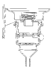
seal
rings. When the stem is vertically raised, at least one valve opens to allow
fluid to
flow from the raised liquid container into a reservoir positioned below; when
the
stem is moved downward, the open valve closes and at least one previously
closed
valve opens to prevent fluid flow from the container while permitting fluid to
be
2
CA 2928480 2018-11-08
dispensed from the reservoir. However, the SurF1exTM dispenser has some
shortcomings in that it fails to provide adequate air flow through the system
as
fluid flows from the container, through and out the reservoir. Such fluid flow
creates a vacuum effect and without sufficient air to take the place of the
fluid, it
causes the SurfiexTM system to dispense fluid slower than desired.
[0010] Other than the SurfiexTM system, none of the systems referenced above
provide an
adequate system for dispensing liquid chemical, which can be hazardous to the
touch. Thus, there remains a need for a liquid dispenser, and liquid chemical
dispenser in particular, that is safe to use and can easily and repeatedly
provide
measured quantities of liquid chemical quickly on demand.
3
CA 2928480 2018-11-08
SUMMARY OF INVENTION
[0011] The dosing device of the present invention is designed to dispense a
specific
amount of liquid, with an emphasis on liquid chemical for various cleaning
applications.
[0012] The dosing device of the present invention is designed to be used with
a fluid
dispensing system that includes a dispenser base and a throated liquid
container.
The dispenser base is attachable to a wall or other surface and includes an
inlet
port with a hollow probe and an outlet port. The throated container is
designed to
hold liquid and includes a spring-biased reciprocating valve assembly inserted
into the throat of a container to control the flow of liquid from the
container.
Normally, the reciprocating valve assembly is in it closed position to prevent
the
liquid from splashing or escaping from the container during handling or
storage.
But, when the container is inverted and positioned over and onto the hollow
probe
on the dispenser base, the hollow probe pushes the valve to its open position
to
allow the chemical to flow out of the container into the dispenser base and
through the outlet port.
[0013] In one embodiment, the dosing device of the present invention includes
a valve
housing, reservoir and dosing cup. The valve housing is mounted to the
dispenser
base and includes an open top, an elongated slot in a side of the housing, an
outlet
port and a blocking region. The reservoir is mounted within the valve housing
and includes at least one inlet port in selective fluid communication with the
dispenser base outlet port and at least one outlet port. The dosing cup is
generally
cylindrical and is rotatably mounted within the valve housing. The dosing cup
has at least one inlet port in selective fluid communication with the
reservoir
outlet port and a blocking region, at least one outlet port and a dosing lever
attached to a side of the dosing cup and extending through the elongated slot
in
the side of the valve housing for rotating the dosing cup between a "fill"
position
to receive liquid and a "dose" position. When the dosing cup is rotated to the
fill
position, the reservoir outlet port and the dosing cup inlet port align to
permit
liquid to flow from the reservoir into the dosing cup and the outlet port of
the
dosing cup and the blocking region of the valve housing align to prevent the
fluid
4
CA 2928480 2018-11-08
in the dosing cup from flowing out of the dosing cup. When the dosing cup is
rotated to the dose position, the reservoir outlet port and the dosing cup
blocking
region align to prevent liquid from flowing from the reservoir into the dosing
cup
and the outlet port of the dosing cup and the outlet port of the valve housing
align
to permit the fluid in the dosing cup to flowing out of the dosing cup and
valve
housing. The fluid travels throughout the dosing device by means of gravity. A
funnel may also be mounted to the bottom of the valve housing to better
control
the flow of the fluid from the valve housing.
[0014] The valve assembly of Anderson Chemical's chemical dosing device
provides an
effective means for quickly and safely delivering a measured dose of the
chemical
from the container to an external container.
BRIEF DESCRIPTION OF THE DRAWINGS
[0015] Referring now to the drawings, wherein like reference numerals indicate
corresponding structure through the several views:
[0016] Figure 1 is Figure 5 of the Morrow Patent No. 6,283,339
[0017] Figure 2 is Figure 6 of the Smith Patent No. 6,550,640;
[0018] Figure 3 is a front view of the dispenser base;
[0019] Figure 3A is a perspective view of the dispenser base;
[0020] Figure 3B is a top view of the dispenser base;
[0021] Figure 4 is a perspective view of one preferred embodiment of the
insert valve
and a front view of a chemical container of the present invention;
100221 Figure 4A is a perspective view of a drawing of a preferred embodiment
of a
chemical container and valve of the present invention;
[0023] Figure 5 is an exploded view of the dosing cup and dispenser base of
the present
invention;
[0024] Figure 6A is a side view of the dosing device of the present invention
with
portions cut away, showing the housing;
[0025] Figure 6B is a perspective view of the dosing device of the present
invention
showing the housing.
[0026] Figure 7 is a perspective view of a reservoir from the top;
CA 2928480 2018-11-08
[0027] Figure 7A is a perspective view of a reservoir from the bottom;
[0028] Figure 8 is a perspective view of a dosing cup from the top;
[0029] Figure 8A is a perspective view of a dosing cup from the bottom;
[0030] Figure 9 is a perspective view of a dosing cup and spacer from the top
illustrating
step 2 of assembling the dosing device of the present invention;
[0031] Figure 10 is a perspective view of an upper disk from the top;
[0032] Figure 10A is a perspective view of an upper disk from the bottom;
[0033] Figure 11 is a perspective view of a funnel from the side;
[0034] Figure 11A is a perspective view of a funnel from the top;
[0035] Figure 12A is a schematic view of a reservoir 0-ring;
[0036] Figure 1211 is sectional view of Figure 12A taken along line A-A;
[0037] Figure 12C is a detailed view of a cross section of the 0-ring along
line 12B
as shown at B in Figure 12A;
[0038] Figure 12D is a perspective view of a sketch of the reservoir 0-ring;
[0039] Figure 12E is a perspective view of the reservoir 0-ring;
[0040] Figure 13A is a schematic view of a dosing cup 0-ring;
[0041] Figure 13B is sectional view of Figure 13A taken along line A-A;
[0042] Figure 13C is a detailed view of a cross section of the 0-ring along
line 13B as
shown in Fig. 13A;
[0043] Figure 14 discloses step 1 of assembling the dosing device of the
present,
including mounting 0-rings to the dosing cup;
[0044] Figure 15 discloses step 3 of assembling the dosing device of the
present,
including inserting the 0-ring onto the upper disk or seal plate;
[0045] Figure 16 discloses step 4 of assembling the dosing device of the
present,
including assembling the upper disk onto the dose cup;
[0046] Figure 17 discloses step 5 of assembling the dosing device of the
present,
including mounting the dosing cup in the housing;
[0047] Figure 18 discloses step 6 of assembling the dosing device of the
present,
including assembling the 0-rings to the bottom of the reservoir;
[0048] Figure 19 discloses step 7 of assembling the dosing device of the
present,
including inserting the reservoir into the housing;
6
CA 2928480 2018-11-08
[0049] Figure 20 discloses step 8 of assembling the dosing device of the
present,
including snapping the funnel onto the bottom of the housing;
[0050] Figure 21 discloses step 9 of assembling the dosing device of the
present,
including attaching the dosing device to the dispenser base;
[0051] Figure 22 discloses step 10 of assembling the dosing device of the
present,
including screwing the dosing device to the dispenser base;
[0052] Figure 23 is a side view of the assembled dosing device of the present
invention
with sections cut away to illustrate the dosing cup in its standby or closed
position;
[0053] Figure 24 is a front view of the assembled dosing device of the present
invention
with sections cut away to illustrate the dosing cup in its empty or open
position;
100541 Figure 25A is a perspective view of the dosing cup and reservoir in the
fill
position.
[0055] Figure 25S is a perspective view of the dosing cup and reservoir as the
dosing cup
is moved from the fill to the dose position, illustrating the orientation of
the outlet
ports and 0-ring seals as they control the flow of liquid chemical or other
liquids.
[0056] Figure 25C is a perspective view of the dosing cup and reservoir as the
dosing cup
is moved from the fill to the dose position, illustrating the orientation of
the outlet
ports and 0-ring seals as they control the flow of liquid chemical or other
liquids.
[0057] Figure 25D is a perspective view of the dosing cup and reservoir in the
dose
position through the reservoir into the dosing cup;
[0058] Figure 26 is a side perspective view of the assembled dosing device of
the present
invention with sections cut away to illustrate the inner workings of the
dosing
device;
[0059] Figure 27 is a front perspective view of the assembled dosing device of
the
present invention with sections cut away to illustrate the inner workings of
the
dosing device;
[0060] Figures 28A and 28B are perspective views of the assembled dosing
device of the
present invention with the dosing cup in its standby or closed position;
[00611 Figure 29 is a front perspective view of the assembled dosing device of
the
present invention;
7
CA 2928480 2018-11-08
[0062] Figure 30 is another side perspective view of the assembled dosing
device of the
present invention;
[0063] Figure 31 is a front view of the assembled dosing device of the present
invention
[0064] Figure 32 is a sectional view of the dosing device taken along line A-
A;
[0065] Figure 33A is a cutaway of the bottom of the reservoir and top of the
dosing cup
with the reservoir outlet ports partially aligned with the cap inlet ports;
[0066] Figure 33B is a cutaway of the bottom of the reservoir and top of the
dosing cup
with the reservoir outlet ports aligned with the blocking region of the cap;
[0067] Figure 34 is a sectional view of an alternate embodiment of the dosing
device
when the dosing cup is in the fill position; and
[0068] Figure 35 is a sectional view of an alternate embodiment of the dosing
device of
Figure 34 when the dosing cup is in the dose position.
8
CA 2928480 2018-11-08
DETAILED DESCRIPTION OF THE INVENTION
[0069] For a thorough understanding of the present disclosure, refer to the
following
detailed description, including the appended claims, in connection with the
above-
described drawings. Although the present disclosure is described in connection
with exemplary embodiments, the present disclosure is not intended to be
limited
to the specific forms set forth herein. It is understood that various
omissions and
substitutions of equivalents are contemplated as circumstances may suggest or
render expedient, but these are intended to cover the application or
implementation
without departing from the spirit or scope of the claims of the present
disclosure.
Also, it is to be understood that the phraseology and terminology used herein
is for
the purpose of description and should not be regarded as limiting.
[0070] The dosing device of the present system is designed to dispense liquids
with an
emphasis on liquid chemical. In order to prevent potentially harmful liquid
chemical from escaping the dosing device, the dosing device comes with a
unique
seat arrangement between the various components of the dosing device. The
dosing device also includes a unique air flow arrangement to ensure rapid
dispensing of liquid.
[0071] The dosing device of the present invention is designed for use with a
fluid
dispensing system similar to that shown in Figures 3, 3A, 3B, 3C, 4 and 4A.
The
fluid dispensing system includes a dispenser base 10 and a liquid container
18.
[0072] The dispenser base 10 is attachable to a wall or other surface and
includes on a
top end, an inlet port 12 with a hollow probe 16 and a shallow cup 13 to
support
the container. The inlet port may be threaded to engage a threaded neck of a
container.
[0073] Air holes 11 extend though the dispenser base to permit air to enter
the dosing
device to allow the liquid to move quickly through the dosing device chambers.
[0074] On the bottom side of the dispenser base is an outlet port 19.
[0075] The liquid container has a throat 20, which, in one embodiment, is
defined by a
threaded neck. The throated container 18 is designed to hold liquid, and in
one
embodiment, liquid chemical.
9
CA 2928480 2018-11-08
[0076] The container further includes a spring-biased reciprocating valve
assembly 22
inserted into the throat of a container to control the flow of liquid from the
container. Normally, the reciprocating valve assembly 22 is in a closed
position
to prevent the liquid from splashing or escaping from the container during
handling or storage. But, when the container 18 is inverted and positioned
over
and onto the hollow probe 16 on the dispenser base, the hollow probe 16 pushes
the valve to its open position to allow the liquid to flow out of the
container into
the dispenser base inlet port 12 and through the outlet port 19.
[0077] In the embodiment shown in Figures 3, 3A, 3B, 3C, 4 and 4A, the
threaded neck
of the container screws into a threaded inlet port and the container is
further
supported by a shallow cup or annular ring 13, however, other embodiments
known in the art for securing the container in sealed relation to the mounting
bracket are anticipated by the present invention.
[0078] The chemical dosing device 100 of the present invention is shown in
exploded
view in Figure 5. The dosing device 100 includes a valve housing 120 (see also
Figures 6 and 6A) that mounts to the bottom of the dispenser base 10 by
screws, a
threaded recess or other suitable means. Mounted within the valve housing 120
is
reservoir 130 for holding liquid (see also Figures 7 and 7A), a dosing cup 140
of
select size (see also Figures 8 and 8A), an optional spacer 150 (see also
Figure 9)
and an upper disk or cap 160 (see also Figures 10 and 10A). A funnel 170 (see
also Figures 11 and 11A) is mounted to the bottom of the valve housing 120 by
a
flexible snap lock or other known means. Various seals, discussed infra, make
the
system leak proof.
[00791 As shown in Figures 6 and 6A, in one embodiment, the valve housing 120
is a
generally hollow cylinder that includes an annular lip 121 for mating the
housing
to the bottom of the dispenser base, over the outlet port 19. The bottom of
the
base includes at least one outlet port 122, a blocking region 129 (the solid
bottom
less the outlet ports), an elongated slot 123 along a longitudinal side of the
valve
housing to receive a handle of the dosing cup when the dosing device is
assembled and a second transverse elongated slot 124 defined along a side 125
of
the valve housing to permit rotational movement of the handle transverse to
the
CA 2928480 2018-11-08
longitudinal axis of the valve housing. A snap lock 127 or other known means
is
provided at the open bottom of the cylinder for attaching funnel 170. A short
protrusion 128 extends upward from the center bottom of the valve housing,
generally along the longitudinal axis of the valve housing, for engaging the
dosing
cup.
100801 As shown in Figures 7 and 7A, reservoir 130 is generally a cylindrical
cup and
includes at the top an upper annular lip 132 for engaging the dispenser base.
The
reservoir also mounts over the dispenser base outlet to receive fluid from the
dispenser base outlet. The reservoir is mounted so air holes 11 in the
dispenser
base are in fluid communication with the reservoir. This allows air to enter
the
reservoir when the reservoir contents are emptied into the dosing cup.
[0081] An annular recess 134 is formed by the annular lip for receiving in
mating
engagement an 0 ring (not shown) to form a tight seal with the bottom of the
dispenser base.
[0082] In a preferred embodiment, as shown in Figure 23, the dispenser base
includes
spacers 200 placed on the bottom surface of the dispenser base, in alignment
with
the lip 121 of the valve housing. When the valve housing is screwed or
otherwise
secured to the bottom of the dispenser base, the spacers limit the compression
on
the reservoir seals and cup seals to prevent over-compression of and damage to
the seals to ensure proper performance.
[0083] The reservoir further includes at least one, and in one preferred
embodiment, two
outlet openings or ports 136 through the bottom of the reservoir. On the
bottom
of the reservoir, for each outlet port 136, there is an arcuate recess 138.
Part of
the recess is concentric with the outlet port; the remainder of the recess
extends
along a blocking region of the reservoir. (The arc of the recess is generally
defined by a distance from the center of the cup to the center of the outlet
port and
has a width greater than the diameter of the outlet port.)
[0084] Outlet port seals 138 (Figures 12A-12E) are mounted within the recess
139
formed on the bottom of the reservoir to form a seal with the top of the upper
disk
160. In one embodiment, seals 138 made of Atlas brand fluoroelastomers with
a 70 Shore A durometer hardness and form a seal between the bottom of the
11
CA 2928480 2018-11-08
reservoir and the top of the upper disk 160 to prevent leakage of liquid
chemical
from the reservoir into the valve housing and dosing cup.
[0085] In a preferred embodiment, the recesses have sides that limit the
compression on
the outlet port seals to prevent over-compression of and damage to the seals
to
ensure proper performance.
[0086] At the bottom of the reservoir is a recess 131A formed by a protrusion
131B
extending upward from the top surface of the bottom of the reservoir. The
recess
engages in mating relation a protrusion 152 from the cap 160 of the dosing
cup.
[0087] Also at the bottom of the reservoir are tabs or spacers 135 that are
generally
positioned between the seal recesses 139. The tabs extend a distance below the
bottom of the reservoir that is roughly equal to the space required for the
seals so
the reservoir will mate properly with the cap 160. Further, this arrangement
allows air to enter the dosing cup while in the dose position, discussed
infra.
[0088] Referring to Figures 8 and 8A, mounted below the reservoir 120 is
dosing cup
140. Dosing cup 140 has an open top 142. Defined at the top of the dosing cup
is
an annular recess for engaging and supporting the cap 160 and a tab 143
extending upward to engage a notch in the cap to keep the cap from rotating on
the dosing cup. (The tab could also be a recess and the cap could be provided
with an engagement tab.)
[0089] The dosing cup includes a dosing lever 146 attached to a side 148 of
the dosing
cup 140. When the dosing cup is mounted within the valve housing, the dumping
handle extends through the transverse slot or opening 124 in the side of the
valve
housing 120 for rotational movement between a "fill" position and a "dose"
position.
[0090] A support spindle 152 extends upward from the center of the top surface
of the
bottom of the dosing cup 140 to support the spacer 150.
[0091] Formed through the bottom of the dosing cup is at least one outlet port
144. The
bottom of the dosing cup is tapered around each outlet port to cause the
liquid to
flow through the outlet port.
[0092] Formed on the bottom of the dosing cup, in alignment with the support
spindle, is
a recess 153 for receiving the protrusion 128 of the valve housing. Also
formed
12
CA 2928480 2018-11-08
on the bottom of the dosing cup are recesses concentric with and larger than
the
outlet ports 144. 0-rings 149 (see also Figure 13A-13C) are mounted within
these recesses to create a seal with the bottom of valve housing 120. In one
embodiment, the 0-rings, 149 are made of Aflas0 brand fluoroelastomers with a
70 Shore A durometer hardness and form a seal between the bottom of the dose
cup and the valve housing.
[0093] In a preferred embodiment, the 0 ring recesses have sides that limit
the
compression on the outlet port seals to prevent over-compression of and damage
to the seals to ensure proper performance.
[0094] Spacer 150 (see Figure 9) of desired size is optionally mounted within
the dosing
cup 140 on spindle 152 to limit the volume of liquid that can be contained in
the
dosing cup 140. Alternatively, the size of the dosing cup can be modified to
define a desired volume of liquid to be -dosed." in one preferred system, dose
chemical products come in product capsule sizes of 64oz or 32oz, although
other
sizes are possible. (A corresponding change in the valve housing may be
necessary.)
[0095] Dosing cups and valve housings can be color coordinated to identify the
quantity
of chemical dispensed. For example, green colored housings indicate that the
dispenser will dispense 1.5oz of chemical concentrate and gold colored
housings
indicate that the dispenser will dispense 0.5oz of chemical concentrate. Other
colors or designs are anticipated by the present invention.
[0096] Referring to Figures 10 and 10A, an upper disk/seal plate/cap 160 is
mounted to
the open top of the dosing cup. The cap includes at least one, and in one
preferred
embodiment two, inlet ports 162 and a blocking region 164. At an outer edge of
the upper disk is a notch for engaging the tab 143 on the dosing cup.
Protrusion
152 extends upward from the top surface of the cap to engage the recess 131A
of
the reservoir.
[0097] On the bottom of the cap, an annular ledge 167 is formed for supporting
an 0-ring
166 (Figure 15). The upper disk prevents liquid chemical from entering or
escaping from the dosing cup 140 except through the cap inlet ports 162 or
dosing
cup outlet ports 144.
13
CA 2928480 2018-11-08
[0098] In an alternate embodiment, the dosing cup and cap can be formed as a
single
unit, eliminating the need for a seal between the cap and the cup.
[0099] To assemble the dosing device of the present invention, the following
steps are
followed:
1. mounting 0-rings to the dosing cup (Figure 14);
2. optionally inserting the spacer into the dosing cup (Figure 9);
3. inserting the 0-ring onto the upper disk or seal plate (Figure 15);
4. assembling the upper disk onto the dose cup (Figure 16);
5. mounting the dosing cup in the valve housing (Figure 17);
6. assembling the seals to the bottom of the reservoir
(Figure 18);
7. inserting the reservoir into the housing (Figure 19);
8. snapping the funnel onto the bottom of the housing (Figure 20);
9. attaching the dosing device to the dispenser base (Figure 21); and
10. screwing the dosing device to the dispenser base Figure 22.
[001001Mounting of the components in this fashion aligns all the component
protrusions
and corresponding recesses to keep the components axially aligned, which in
turn
keeps the inlet and outlet ports properly aligned.
[001011Referring to Figures 23-31, in operation, the liquid container delivers
liquid to the
reservoir continuously. Further, the dosing cup is normally in its fill
position (and
can be biased in such position by a spring mechanism, not shown). Liquid is
moved through the dispenser and dosing device by alignment or misalignment of
the various component inlet and outlet ports caused by rotation of the dosing
cup.
[00102] In the fill position, the reservoir outlet ports are aligned with the
inlet ports of the
cap, allowing liquid to enter the dosing cup. Simultaneously, the outlet ports
of
the dosing cup are aligned with the blocking region blocking region of the
valve
housing, preventing the liquid from escaping from the valve housing. Air
enters
the reservoir though air holes 11 in the dispensing base to expedite the flow
of
liquid.
[00103] Using the dump lever to rotate the dosing cup to the "dose" position
causes the
cap, which is fixed in position with respect to the dosing cup, to rotate so
that the
outlet ports of the reservoir are aligned with the blocking area of the cap
14
CA 2928480 2018-11-08
preventing fluid from entering the dosing cup, and the dosing cup outlet ports
are
aligned with the outlet ports of the valve housing, allowing the liquid to be
dispensed in measured dose or quantity (matching the dosing cup capacity, with
or without spacer 150) from the valve housing. The funnel directs the fluid
from
the valve housing outlet ports in a narrow stream to a desired external
container.
1001041As fluid exits the dosing cup, air is drawn through the valve housing
as shown in
Figure 24. Because the cap inlet ports are no longer aligned with the
reservoir
outlets or the reservoir seals, and the reservoir base is spaced from the top
surface
of the cap as shown in Figures 33A and 33B, air is able to enter the dosing
cup,
expediting the flow of liquid from the dosing cup, out of the valve housing.
[00105] Rotating the dosing cup back to the fill position permits the dosing
cup to be
refilled.
100106] The benefits of Applicant's arcuate seals on the bottom of the
reservoir are best
understood by reference to Figures 25A-25D. As shown, the seals include a
first
circular portion 300 (Figure 12A) that is concentric with the reservoir outlet
(or
other shape dependent on the shape of the outlet port). A second portion 310
is an
arcuate extension off the first portion of the seal. This section of the seal
will
prevent leakage of liquid that would otherwise occur in the absence of the
second
portion of the seal.
[00107] Referring to Figure 25A, when the dosing cup is in the "Fill"
position, liquid in
the reservoir can enter the dosing cup through the aligned reservoir outlet
ports
and the cap/dosing cup inlet ports. As the dosing cup is rotated to the
position
shown in Figure 25B, the reservoir outlet port is no longer aligned with the
cap
inlet port. Given the spatial separation between the bottom of the reservoir
and
the top of the cap, liquid would leak from this area without the second
portion of
the seal. However, the second portion of the seal maintains the seal between
the
reservoir and the cap during this transition from Fill to Dose position,
preventing
leakage. A recess 320 in the bottom of the reservoir, above the second portion
of
the seal (Figures 33A and 33B), provides space to trap what little liquid that
might
have escaped the reservoir during the transition from Fill to Dose positions.
CA 2928480 2018-11-08
These same Figures also illustrate how air is allowed to enter the dosing cup
to
facilitate release of the liquid from the dosing cup.
1001081 In another preferred embodiment, shown in Figures 34 and 35, the
reservoir can
be incorporated into the dispenser base.
[00109] In another embodiment, rather than using a rotatable dosing cup to
align the inlet
and outlet ports of the components of the dosing device, a linearly movable
dosing cup can be utilized. Other shapes of the cup are also therefore
possible.
[00110] In another preferred embodiment, the cap can be glued or welded to the
dosing
cup (dependent on material) to eliminate the need for an 0 ring seal.
[00111] In another preferred embodiment, the cap can be stainless steel or
other materials
that create less friction when the dosing cup is rotated and provide greater
wear
over time.
[00112] In another embodiment, the dosing device can be horizontally mounted.
[00113] In this manner, the valve assembly of Anderson Chemical's chemical
dosing
device provides an effective means for delivering a measured dose of the
chemical from the container to the funnel and the ultimate destination point.
16
CA 2928480 2018-11-08