Note : Les descriptions sont présentées dans la langue officielle dans laquelle elles ont été soumises.
CA 02930219 2016-05-10
WO 2015/079401
PCT/1B2014/066389
APPLICATION FOR PATENT
Inventors: Daniel YACHIA and Valentin PONOMARENKO
Title: FILTRATION AND ENTRAPMENT APPARATUS AND METHOD OF
USE
CROSS REFERENCES TO RELATED APPLICATIONS
This patent application is related to and claims priority from commonly owned
U.S. Provisional Patent Application Serial No. 61/910,065, entitled:
FILTRATION AND
ENTRAPMENT APPARATUS AND METHOD OF USE, filed on November 28, 2013,
the disclosure of which is incorporated by reference herein in its entirety.
BACKGROUND
The present invention relates to filtration devices for use in surgical
settings inside
the body. During surgical procedures, such as cardiovascular procedures, for
example,
valve replacement, there is a possibility that particulate and tissue matter
can break away
from the main tissue and enter the blood stream. If this particulate enters
the blood
stream, it can clog blood vessels, for example, in the brain, leading to a
stroke, or in the
lungs, kidneys or intestines leading to an embolism, all catastrophic
conditions. It is
believed that these situations may occur in up to 15% of cardiovascular
surgeries and
procedures.
Current technology uses filters, to cover the connection points of the vessels
reaching the brain in the aortic arch, but does not filter any particulates
that may flow
through the aortic arch into the blood stream of the descending aorta.
Accordingly, the
potential for some of the catastrophic dangers remain.
1
CA 02930219 2016-05-10
WO 2015/079401
PCT/1B2014/066389
SUMMARY
Embodiments of the present invention are directed to filter systems which
comprise an expandable filter, with a first end of the filter attached to an
end of a first
tube, and a second end of the filter attached to an end of a second tube. The
tubes are
arranged telescopically with respect to each other such that telescopic
movement of the
first and second tubes with respect to each other causes the filter to move
between a first
collapsed position and a second expanded position, where the filter extends
outwardly.
The filter may be a folded-over member, when in the expanded position, or a
spiraling
member.
Embodiments of the present invention are directed to filters, that are
introduced to
surgical sites in a collapsed position, and are then expand to an outwardly
expanded or
extended position upon being released at the surgical site by the movement or
withdrawing of a covering tube, or overtube. The filters, along the edges,
appose to the
vessel wall, with the requite vessel of tissue, preventing particulates from a
surgical site
from moving beyond the surgical site and into the circulation, or tissue,
where such
particulates could cause catastrophic damage. The filters are typically multi-
layered, in
order to maximize the amount of particulates which can be captured and
trapped.
Embodiments of the present invention are directed to a filter system. The
filter
system comprises: a first tube; a second tube, the first tube and second tube
movable
relative to each other in at least a partially telescoping arrangement; and, a
filter. The
filter is such that s first end of the filter is supported by the first tube
and a second end of
the filter is supported by the second tube, and the filter is movable between
a collapsed
position, when at least partially covered by the second tube, and an expanded
position,
when uncovered by the second tube.
Optionally, the filter comprises a foldable member movable by the movement of
the first and second tubes from a folded-over outwardly expanded orientation,
defining
the expanded position, to an inverted orientation defining the collapsed
position.
Optionally, the filter system additionally comprises: a third over tube for
enveloping the first and second tubes, the first tube defining an inner tube
and the second
tube defining a mid tube, the third tube moveable so as to cover and uncover
the filter,
2
CA 02930219 2016-05-10
WO 2015/079401
PCT/1B2014/066389
the first, second and third tubes moveable with respect to each other.
Optionally, the first, second, and third tubes are telescopically arranged
with
respect to each other.
Optionally, the filter includes a frame and a mesh covering the frame.
Optionally, each of the first, second, and third tubes include a
longitudinally
extending slit for allowing the first, second and third tube to temporarily
separate laterally
outward along the longitudinally extending slit to accommodate instrumentation
passing
through the first, second and third tubes.
Optionally, the first second and third tubes are made of a resilient material
to
accommodate laterally outward movement of the tube portions on oppositely
disposed
sides of the longitudinally extending slit from an open closed position to an
open position
and the for returning the first, second, and third tubes to the closed
position once the
instrumentation has passed through the first, second, and third, tubes.
Optionally, the filter system additionally comprises: a delivery catheter for
passage of instrumentation through the inner tube to a predetermined site and
the
instrumentation includes at least one of stents and valves.
Optionally, the filter comprises: a wire including a first end in
communication
with the first tube, and, a second end extending into the second tube; and, a
net supported
by the wire, to define a filter.
Optionally, the wire defines the periphery of the filter.
Optionally, the net extends from the first tube to the wire and the net runs
along
the first tube.
Optionally, the wire is of a resilient material and exhibits spring-like
behavior.
Optionally, the wire extends along the first tube in a helical orientation
between
the first end of the wire and the second end of the wire.
Optionally, the wire extends through the second tube to outside the filter
system.
Optionally, the wire attaches to the second tube.
Optionally, the filter system additionally comprises a third tube for moving
over
at least a portion of the first tube and at least a portion of the second
tube, the third tube
for enveloping the filter in the collapsed position, and for moving beyond the
filter when
the filter is in the expanded position.
3
CA 02930219 2016-05-10
WO 2015/079401
PCT/1B2014/066389
Embodiments of the present invention are directed to a filter system. The
filter
system comprises: an outwardly expandable filter, with a first end of the
filter attached to
an end of a first tube, and a second end of the filter attached to an end of a
second tube.
The first and second tubes arranged telescopically with respect to each other
such that
telescopic movement of the first and second tubes with respect to each other
causes the
filter to move from a folded-over outwardly expanded orientation to an
inverted
orientation.
Optionally, the filter system additionally comprises: a third over tube for
enveloping the first and second tubes, the first tube defining an inner tube
and the second
tube defining a mid tube, the third tube moveable so as to cover and uncover
the filter,
the first, second and third tubes moveable with respect to each other.
Optionally, the first, second, and third tubes are telescopically arranged
with
respect to each other.
Optionally, the filter includes a frame and a mesh covering the frame.
Optionally, each of the first, second, and third tubes include a
longitudinally
extending slit for allowing the first, second and third tube to temporarily
separate laterally
outward along the longitudinally extending slit to accommodate instrumentation
passing
through the first, second and third tubes_
Optionally, the first second and third tubes are made of a resilient material
to
accommodate laterally outward movement of the tube portions on oppositely
disposed
sides of the longitudinally extending slit from an open closed position. to an
open position
and the for returning the first, second, and third tubes to the closed
position once the
instrumentation has passed through the first, second, and third, tubes.
Optionally, the filter system additionally comprises: a delivery catheter for
passage of instrumentation through the inner tube to a predetermined site.
Optionally, the instrumentation includes at least one of stents and valves.
Optionally, the filter system additionally comprises: a delivery catheter for
passage of the instrumentation through the inner tube to a predetermined site,
and
optionally, the instrumentation includes at least one of st.ents and valves.
Embodiments of the present invention are also directed to another filter
system.
The filter system comprises: a first tube and a second tube, with the first
tube moveable
4
CA 02930219 2016-05-10
WO 2015/079401
PCT/1B2014/066389
at least partially within the second tube; and, a filter moveable between a
collapsed
position and an expanded position. The filter includes, a wire including a
first end in
communication with the first tube, and, a second end extending into the second
tube; and,
a net supported by the wire, to define a filter.
Optionally, the wire defines the periphery of the filter.
Optionally, the net extends from the first tube to the wire and the net runs
along
the first tube.
Optionally, the wire is of a resilient material and exhibits spring-like
behavior.
Optionally, the wire extends along the first tube in a helical orientation
between
the first end of the wire and the second end of the wire.
Optionally, the wire extends through the second tube to outside the filter
system.
Optionally, the wire attaches to the second tube.
Optionally, the filter system additionally comprises a third tube for moving
over
at least a portion of the first tube and at least a portion of the second
tube, the third tube
for enveloping the filter in the collapsed position, and for moving beyond the
filter when
the filter is in the expanded position.
Embodiments of the present invention are directed to a method for catching
particulates associated with a medical procedure. The method comprises:
providing a
filtration system, deploying the filtration apparatus to the surgical site in
the collapsed
position; and causing the filter to expand outward to the expanded position
into contact
with tissue to form a barrier with the tissue, for catching and entrapping
particulates. The
filtration system comprises: a first tube; a second tube, the first tube and
second tube
movable relative to each other in at least a partially telescoping
arrangement; and, a filter,
a first end of the filter supported by the first tube and a second end of the
filter supported
by the second tube, the filter movable between a collapsed position when at
least partially
covered by the second tube, and an expanded position, when uncovered by the
second
tube.
Optionally, the tissue includes the walls of vessels.
CA 02930219 2016-05-10
WO 2015/079401
PCT/1B2014/066389
Some embodiments of the present invention are directed to a method for
catching
particulates associated with a medical procedure. The method comprises
providing a
filtration apparatus comprising an outwardly expandable filter, a first end of
the filter
attached to an end of a first tube and a second end of the filter attached to
an end of a
second tube. The first and second tubes are arranged telescopically with
respect to each
other, with the first tube inside of the second tube, such that telescopic
movement of the
first and second tubes with respect to each other causes the filter to move
from a folded-
over, outwardly expanded, orientation to an inverted orientation. The
filtration apparatus
is then deployed to the surgical site such that the filter expands outward
into contact with
the walls of a vessel to form a bather, for catching and entrapping embolic
material
particul ates.
Optionally, the method additionally comprises moving the first tube and the
second tube telescopically with respect to each other, such that substantially
all of the
filter is in an inverted orientation, for trapping and preventing backflow of
particulates,
inside the second tube.
Optionally, the method additionally comprises removing the filtration
apparatus
from surgical site, and also optionally, removing the filtration apparatus
from the surgical
site includes removing the filtration apparatus from the body.
Unless otherwise defined, all technical and/or scientific terms used herein
have
the same meaning as commonly understood by one of ordinary skill in the art to
which
the invention pertains. Although methods and materials similar or equivalent
to those
described herein can be used in the practice or testing of embodiments of the
invention,
exemplary methods and/or materials are described below. In case of conflict,
the patent
specification, including definitions, will control. In addition, the
materials, methods, and
examples are illustrative only and are not intended to be necessarily
limiting.
BRIEF DESCRIPTION OF THE SEVERAL VIEWS OF THE DRAWINGS
Some embodiments of the present invention are herein described, by way of
example only, with reference to the accompanying drawings. With specific
reference now
6
CA 02930219 2016-05-10
WO 2015/079401
PCT/1B2014/066389
to the drawings in detail, it is stressed that the particulars shown are by
way of example
and for purposes of illustrative discussion of embodiments of the invention.
In this
regard, the description taken with the drawings makes apparent to those
skilled in the art
how embodiments of the invention may be practiced.
Attention is now directed to the drawings, where like reference numerals or
characters indicate corresponding or like components. In the drawings:
FIG. lA is a perspective view of a system including some embodiments of the
invention;
FIGs. 1B and 1C are perspective views of an area AA of FIG. IA;
FIG. 10 is a perspective partial cut away view of the system of FIG. 1A
showing
attachments of a filter, in accordance with some embodiments of the invention;
FIG. lE is a perspective cut away view of the area BB of FIG. ID;
FIG. 1F is a perspective cut away view of the area CC of FIG. 1D;
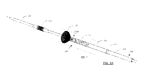
FIG. 2A is a perspective view of a the system of FIG. lA showing the filter in
an
extended position;
FIGs. 2B is a longitudinal section an area DD of FIG. 2A;
FIG. 3A is a diagram of the position of all the catheters in their beginning
state
where all tubes are covering the filter;
FIG. 3B is a diagram after retraction of the over tube to release and allow
expansion of a part of the filter to expand to a 2-layered funnel shaped
member;
FIG. 3C is a diagram of the position of the catheters at the end of the
procedure
with the filter retracted and the inner and mid tubes covered by the over
tube;
FIG. 3D is a diagram showing an exemplary operation of some embodiments of
the invention of FIG. 1A;
FIG. 3E is a sectional view of the apparatus of FIGs. IA and 2A deploying a
valve, which may be associated with a stent, in an exemplary operation;
FIG. 4 is a perspective view of an alternative apparatus in accordance with
embodiments of the present invention;
7
CA 02930219 2016-05-10
WO 2015/079401
PCT/1B2014/066389
FIG. 5A is a perspective view of another alternative apparatus in accordance
with
embodiments of the present invention;
FIG. 5B is a perspective view of an alternative filter support mechanism of
the
embodiment of FIG. 5A; and,
FIG. 6A, 6B and GC are perspective views of an alternative apparatus in
accordance with embodiments of the present invention.
DETAILED DESCRIPTION OF THE DRAWINGS
FIGs. 1A-1F shows an apparatus 100, for example, a surgical tube system, in
accordance with some embodiments of the invention. The apparatus 100 is formed
of,
for example, moving from inner to outer, an inner tube 101, a mid tube 102,
and an over
tube 103. The tubes 101-103 are typically in a telescopic arrangement with
respect to
each other, and are, for example, concentric and coaxial along a
longitudinally extending
axis.
The apparatus 100 is shown with a delivery catheter 105, which extends through
the inner tube 101, and is shown supporting instrumentation, such as a stent
supported
valve 110 (hereinafter, "valve 110"). This stent supported valve 110 is formed
of a stent
110a and valve 110b, as shown in detail in FIG. 3E, for implantation in the
heart.
Alternately, the valve 110 may be only a valve, absent support by a stent.
Throughout this document, a "tube" is any kind of surgical tube, catheter,
instrument, device, or cannula having a cylindrical outer body with a hollow
interior to
accommodate additional tubes, catheters, instruments, devices, cannulas and
the like.
While this three tube structure for the apparatus 100 is shown, additional
tubes,
strips or wires internal, intermediate and external may also be used with this
apparatus
100. All of the tubes 101, 102, 103, are moveable with respect to each other,
and
steerable, individually and in combinations, by the operator. The same holds
true for
delivery catheter 105. The tubes 101-103 of the apparatus 100 system are, for
example,
conventional catheters, such as those commonly used in cardiac
catheterization. The
distal end of the apparatus 100 is represented by 100d, while the proximal end
of the
apparatus is represented by 100p. The distal end 100d, is typically within the
body, while
the proximal end 100p is typically outside the body, being manipulated by the
operator
8
CA 02930219 2016-05-10
WO 2015/079401
PCT/1B2014/066389
performing the requisite procedure with the apparatus 100. All of the tubes
101-103
include distal and proximal ends oriented in accordance with the distal end
100d and the
proximal end 100p of the apparatus 100. Movement in the distal direction, or
distal
movement, is in the direction of the distal end 100d, while movement in the
proximal
direction or proximal movement is in the direction of the proximal end 100p.
The inner 101 and mid 102 tubes support a filter 112. The filter 112 attaches
to
the inner tube 101 and the mid tube 202, as shown in FIGs. 1D, 1E 1F and 2B.
As shown
in detail in FIG. 2B which is a longitudinal section of this segment, the
inner layer 112a
of the filter 112 attaches, for example, to the distal end 101d of the inner
tube 101 (e.g., at
the inner tube 101 distal edge 101de) (FIG. 2B), or alternately, the inner
side 101x of the
inner tube 101 and, the outer layer 112b of the filter 112 attaches to the
distal end 102d of
the mid tube 102 (e.g., at the mid tube 102 distal edge 102de) , or
alternately, the outer
side 102y of the mid tube 102 (FIG. 2B). The over tube 103 can, for example,
serve as an
introducer catheter for the apparatus 100.
The attachments of the filter 112 layers (inner layer 112a and outer layer
112b) to
the respective inner 101 and mid 102 tubes, is, for example, by fasteners such
as solder,
glue and the like. Alternately, the filter layers 112a, 112b may also continue
along the
tube (inner tube 101 and mid tube 102) as a reinforcement. This attachment or
the
continuation arrangement allows for the filter 112 to be pushed and pulled, so
that it folds
inward, while the inner surface of the filter is pulled proximally whereby the
embolic
material, particulates and the like, is entrapped between the inner surface of
the filter 112
and the shaft of the delivery catheter 105 in the filter 112.
The filter 112 is initially in a compressed position, where a short portion of
the
filter 112 is folded inward, and one end of the filter 112 is attached to the
distal edge
101de of the inner tube 101, while the other end of the filter 112 is attached
to the distal
edge 102de of the mid-tube 102. The filter 112 is packed and covered by the
over tube
103. The filter 112, is for example, of a medical grade material, such as
nitinol or other
metal alloys, medical grade stainless steel or, natural silk or synthetic
wires or threads,
such as PEEK (Polyether Ether Ketone) wire or thread or any of the
aforementioned
materials as braided or knitted wire of approximately 40-50 microns in
diameter,
resulting in openings of approximately 100 microns. This filter 112 size
allows for the
9
CA 02930219 2016-05-10
WO 2015/079401
PCT/1B2014/066389
filter 112 to catch, trap and retain particulate, e.g., calcified tissue,
plaque and other fatty
tissue, which may come loose during the valve implant procedure, while
allowing bold to
flow through the filter 112. The material for the filter 112 is also flexible
and resilient,
allowing the filter 112 to expand outward, for example, radially, into a bell
or funnel
shape, when the over tube 103, is retracted from covering the filter 112, as
shown in
FIGs. 2A, 2B, 3B and 3D.
Turning also to FIG. 3A, the filter 112 is initially packed in a compressed
(and
folded) position (Position 0), where a portion of the filter 112 extends over
the inner tube
101, as it is packed and covered by the over tube 103.
The filter 112 is folded such that it is double layered, such that
particulates that
may pass through the first or inner layer 112a are caught and trapped by the
second or
outer layer 112b. The unfolded filter 112 has openings up to 100 microns to
allow blood
flow but to capture embolic material larger than 100 microns. When folded upon
itself,
the double layered filter can capture smaller embolic material particles.
An exemplary operation of the apparatus 100 is shown in FIG. 3D. Initially,
the
apparatus 100 has been deployed to the proper surgical site, for example,
through the
aorta 120, for a cardiac procedure such as Trans-Aortic Valve Replacement
(TA.VR), by
conventional cardiac catheterization and access procedures, such as through
vessels in the
leg or the arm. Specifically, in FIG. 3D, the apparatus 100 is such that the
filter 112 is
proximally positioned with respect to the valve 110, and the apparatus 100 is
inserted
through the aorta, for example, by trans-aortic insertion.
The process of FIG. 3D continues as shown in FIG. 3E, where the apparatus 100
is such that the filter 112 is proximally positioned with respect to the stunt
supported
valve 110. The apparatus 100 is inserted through the aorta 120, as a part of
the delivery
catheter 105, for example, by trans-aortic insertion. Insertion of the device
can be done
also through the subclavian or axillary artery.
To activate/expand the distal part of the filter 112, the over tube 103 is
moved
proximally, in the direction of the arrow 114, with respect to inner 101 and
mid 102
tubes. The filter 112, upon release from the outermost over tube 103, expands
outward,
as per the arrow 115 (to Position I of FIG. 3B). The filter 112 expands, for
example, into
a bell/funnel shape, and its edges come into contact with the vessel walls, to
block,
CA 02930219 2016-05-10
WO 2015/079401
PCT/1B2014/066389
capture and trap, particulate from traveling through the vessel to other
unintended
locations in the body, but allowing passage to blood to flow. The filter 112
expansion is
such that the filter 112 extends to the vessel (i.e. aorta) 120 walls 122, and
into contact
with these walls 122, to form a barrier against particulate travel beyond the
filter 112, as
shown in FIG. 3D. Accordingly, particulates are caught and trapped between the
filter
112 and the shaft of the delivery catheter 105, before the particulates can
enter the blood
vessels 124a-124c of the aorta 120 (brachio-cephalic arch 126), or flow
downstream in
the descending aorta 120' to other vessels or locations in the body. By
catching and
trapping the particulates in the filter 112, catastrophic outcomes, caused by
particulates,
such as vessel and organ blockages, strokes, and the like, can be prevented.
The delivery catheter 105 is movable within the inner tube 101 and the filter
112,
to perform the requisite procedure, e.g., valve replacement, in the heart 128.
When the
valve deployment system reaches its target the overtube 103 is moved
proximally to
allow expansion of the filter. Then the mid tube 102 is pushed distally (in
the direction of
the arrow 116a), while the inner tube 101 is pulled proximally (in the
direction of the
arrow 116b), for example, simultaneously or contemporaneously, such that the
inner
layer 112a of the filter 112 retracts around the delivery catheter. The inner
tube 101 is
positioned proximally with respect to the distal end of the mid tube 102, as
the filter 112
is now extending between the distal ends of the mid 102 and inner 102 tubes.
At the end
of the procedure the over tube 103 is moved distally (in the direction of the
arrow 117), to
cover the end of the filter 112 (Position 2 of FIG. 3C).
With the filter 112 now within the apparatus 100, the inner tube 101 and the
mid
tube 102, with the filter 112 (and the caught and trapped particulates),
together with the
valve delivery system can be removed from the body. This is performed, for
example, by
the inner 101 and mid 102 tubes being pulled proximally through the over tube
103,
leaving the body through the vessels in the leg or arm.
Alternatively, the filter 112 may attached to the inner 101 and mid 102 tubes
as
shown above, with the inner 101 and mid 102 tubes joined, resulting in a
double layer
static filter, which would look and function similar to the filter 112 of
FIGs. 2A and 2B.
In such a case there is no relative movement between the inner 101 and the mid
tube 102,
due to their being joined. As a result, this alternative filter would maintain
the folded over
11
CA 02930219 2016-05-10
WO 2015/079401
PCT/1B2014/066389
bell shape, upon the filter being released from the over tube 103. The filter
112
subsequently returns to its retracted or packed state, when the over tube 103
is moved
(distally) over the filter 112, or when the fixed mid 102 and inner 101 tubes
are moved
proximally, or combinations of these movements, when removal of the inner 101
and mid
102 tubes with the filter 112, from the body is desired.
While the apparatus 100 is shown in a cardiac operation, this is exemplary
only.
The catheter system 100 can be used in other body locations and vessels,
including other
blood vessels, bile ducts and other ducts, urinary tracts, and brain
passageways and other
tubular structures in the body. Additionally, while a double layer filter is
shown, other
multiple layer bell shaped filters are also permissible.
FIG. 4 shows an alternative apparatus 200, with a filter 212. This apparatus
200
is similar in all aspects and operation to the apparatus 100, with similar
components
having the same numbering as in the apparatus 100, but in the 200's, whose
components
which are not specifically mentioned in accordance with those for the
apparatus 100. In
this alternative apparatus 200, the over tube 203 (and also the inner 201 and
mid 202
tubes) are split to accommodate the delivery catheter 105 in their respective
central
lumens. The splits 203', 202', 201' typically extend longitudinally and is
movable
laterally outward, to accommodate the passage of the delivery catheter 105
(with the
valve 110), when the delivery catheter 105 is moved distally, through the
three tubes 201,
202, 203.
This split over tube 203 (and split inner 101 and mid 102 tubes) allows for
the
additional size, e.g., diameter of the delivery tube 105, for example, with
the valve 110,
to pass through these tubes 201, 202, 203 to a position for deployment, such
as that
shown in FIG. 3D. With the passage of the valve end complete, the over tube
203, mid
tube 202 and inner tube 201 all move inward to their original positions. The
over tube
203, mid tube 202 and inner tube 201 are movable between its inward and
outward
orientations due to their being made of a resilient material, metal or nitinol
wire
reinforced.
FIG. 5A shows an alternative filter 312 for the apparatus 100. The filter 312
fonned of a support structure 313a or frame of braided nitinol or metal mesh
313a, and
dense net or mesh 313b, over the support structure 313a. The net or mesh 313b
performs
12
CA 02930219 2016-05-10
WO 2015/079401
PCT/1B2014/066389
embolic material filtering. The filter 312 includes inner 312a and outer 312b
layers that
attach to the respective inner 101 and mid 102 tubes of the apparatus similar
to that for
the filter 112, as detailed above. The filter 312 is such that -the covering
net or mesh 313b
is of materials such as nitinol, polymer fibers or silk, at porosities such as
80-150
microns.
FIG. 5B shows an alternate filter 312' to that of the filter 312 of FIG. 5A,
for use
with the apparatus 100, as detailed above. The filter 312' is retractable,
e.g., collapsible,
and extendable, e.g., expandable, from a tube of the apparatus 100, for
example, the inner
tube 101. Alternately, the filter 312' may be mounted on an inner tube 101 or
mid tube
102, for example, at the distal edges 101de, 102de of the inner tube 101 or
mid tube 102,
respectively, similar to that for the filter 112 detailed above. The filter
312' is retracted
from the respective inner 101 or mid 102, similar to that described for the
filter 112
above.
The filter 312' is formed of frame 353a of metal wires 353aa, for example, in
a
bell shape, which in turn, connect to a balloon 353b, or other outwardly
expanding
support member. The balloon 353b is typically in a peripheral ring at the
distal end of the
frame 353a that is inflatable, with air, gas, liquid or the like, to support
the distal end of
the frame 353a in the expanded position as shown for supporting the inward
rolling filter
net or mesh. The balloon is inflated through one of the arms of the frame
which is tubular
The frame 353a, in particular, the wires 353aa, serve to support a net or mesh
(not
shown), which is similar to the net or mesh 313b, 413b, 413c detailed above
for filters
312, 412, respectively.
FIGs. 6A-6C show an alternative apparatus 400 formed of an inner tube 401 and
a
mid tube 402, with an overtube 403, in a telescoping arrangement, and for
example,
concentric and coaxial along a longitudinal axis. The inner tube can be the
valve delivery
catheter. These alternative apparatus 400 include filters 412, 412', 412".
These filters
412 of FIG. 6A, 412' of FIG. 6B, and 412" of FIG. GC are spiraling filters.
For example,
the spirals result in conical filter segments, with the cones ponting
proximally. The
spirals are arranged serially, to catch particles that could pass through
previous upstream
spirals. Elements of the apparatus 400 which are not specifically mentioned,
but have the
same numbers in the "400s" as the apparatus 100, the structures of the
alternative
13
CA 02930219 2016-05-10
WO 2015/079401
PCT/1B2014/066389
apparatus 400 are similar to those detailed above for the apparatus 100, and
are in
accordance with the descriptions provided above.
Each spiraling filter 412, 412', 412" includes a pre-shaped support, such as a
wire
413a, oriented, for example, in a helix, defining the periphery of the filter
412, 412',
412". The wire 413a, is for example, nitinol, or any other suitable material,
with nitinol
typically used due to its shape memory retaining properties, as well as its
spring-like
behavior (e.g., resilience). The wire 413a defines the outer periphery of the
filter 412,
412', 412", and supports a ribbon-shaped net 413b. The net 413b is similar to
the net or
mesh detailed above, for fine filtration. The inner edge 413bx connects to the
shaft of the
inner tube 401. The inner tube 401 may also serve, for example, as a delivery
catheter for
the instrumentation, such as the valve 110, similar to that as described above
for the
delivery catheter 105.
The inner edge 413bx of the net 413b attaches to the inner tube 401 in a
spiral
manner, for example, either by a mechanical attachment, including by being
wrapped
around the inner tube 401. The distal end 413aa of the wire 413a attaches to
the inner
tube 401at the distal end of the inner tube 401. The proximal end 413ab of the
wire 413a
attaches to the mid-tube 402, or extends through the inner tube 401 or mid
tube 402, to
outside of the apparatus 400, where it can be manipulated, for example, pulled
to collapse
the filter 412, 412', 412", by the operator.
The filters 412, 412', 412" are expandable from the mid tube 402, when the mid
tube 402 or over tube 403 are moved proximally, inner tube 401, and in some
instances,
the mid tube 402) are moved distally, allowing the filter 412, 412', 412" to
release, such
that it expands laterally outward. The filters 412, 412', 412" are retractable
into the mid
tube 402 and/or the over tube 403 (when the wire 413a is pulled by the mid
tube 402).
Both of these aforementioned actions cause the filter 412, 412', 412" to
collapse. The
mid tube 402 and the inner tube 401 are then moved proximally into the over
tube 403, or
the mid tube 402/over tube 403 is moved distally over the now-collapsed filter
412, 412',
412" of the inner tube 401.
Should the proximal wire 413ab extend through the inner tube, pulling the
proximal end of the wire will collapse the filter. The apparatus 400 of FIGs.
6B and 6C
include a net or mesh sleeve 413c around the respective filters 412', 412", of
a net or
14
CA 02930219 2016-05-10
WO 2015/079401
PCT/1B2014/066389
mesh material the same or similar to that of the net or mesh 413b detailed
above. This
net or mesh sleeve 413c serves as an additional protective filtration element
for particles
that can escape from the outer sides of the filter 412', 412", as defined by
the wire 413.
FIG. 6B differs from FIG. 6C, as it may protect the openings of the arteries
124a-124c of
the brachiocephalic arch 126 (FIG. 3D, 3E) reaching the brain in case
particles escape
between the edges of the filter or if the entire apparatus 400 is positioned
in a manner that
it cannot protect these arteries. FIG. 6B also differs from FIG. 6C as the
respective filters
412', 412" can be collapsed, as wire 413ab is pulled by proximally pulling the
mid tube
402, whereas in FIG.6C the wire 413ab is pulled directly.
The present invention, while shown for human use, is also suitable for animal
use.
The descriptions of the various embodiments of the present invention have been
presented for purposes of illustration, but are not intended to be exhaustive
or limited to
the embodiments disclosed. Many modifications and variations will be apparent
to those
of ordinary skill in the art without departing from the scope and spirit of
the described
embodiments. The terminology used herein was chosen to best explain the
principles of
the embodiments, the practical application or technical improvement over
technologies
found in the marketplace, or to enable others of ordinary skill in the art to
understand the
embodiments disclosed herein.
The terms "comprises", "comprising", "includes", "including", "having" and
their
conjugates mean "including but not limited to".
As used herein, the singular form "a", "an" and "the" include plural
references
unless the context clearly dictates otherwise. For example, the term "a
compound" or "at
least one compound" may include a plurality of compounds, including mixtures
thereof.
The word "exemplary" is used herein to mean "serving as an example, instance
or
illustration." Any embodiment described as "exemplary" is not necessarily to
be
construed as preferred or advantageous over other embodiments and/or to
exclude the
incorporation of features from other embodiments.
The word "optionally" is used herein to mean "is provided in some embodiments
and not provided in other embodiments". Any particular embodiment of the
invention
may include a plurality of "optional" features unless such features conflict.
Throughout this application, various embodiments of this invention may be
CA 02930219 2016-05-10
WO 2015/079401
PCT/1B2014/066389
presented in a range format. It should be understood that the description in
range format
is merely for convenience and brevity and should not be construed as an
inflexible
limitation on the scope of the invention. Accordingly, the description of a
range should
be considered to have specifically disclosed all the possible subranges as
well as
individual numerical values within that range. For example, description of a
range such
as from I to 6 should be considered to have specifically disclosed subranges
such as from
1 to 3, from 1 to 4, from 1 to 5, from 2 to 4, from 2 to 6, from 3 to 6 etc.,
as well as
individual numbers within that range, for example, 1, 2, 3, 4, 5, and 6. This
applies
regardless of the breadth of the range.
Whenever a numerical range is indicated herein, it is meant to include any
cited
numeral (fractional or integral) within the indicated range. The phrases
"ranging/ranges
between" a first indicate number and a second indicate number and
"ranging/ranges
from" a first indicate number "to" a second indicate number are used herein
interchangeably and are meant to include the first and second indicated
numbers and all
the fractional and integral numerals therebetween.
It is appreciated that certain features of the invention, which are, for
clarity,
described in the context of separate embodiments, may also be provided in
combination
in a single embodiment. Conversely, various features of the invention, which
are, for
brevity, described in the context of a single embodiment, may also be provided
separately
or in any suitable subcombination or as suitable in any other described
embodiment of the
invention. Certain features described in the context of various embodiments
are not to be
considered essential features of those embodiments, unless the embodiment is
inoperative
without those elements.
Although the invention has been described in conjunction with specific
embodiments thereof, it is evident that many alternatives, modifications and
variations
will be apparent to those skilled in the art. Accordingly, it is intended to
embrace all such
alternatives, modifications and variations that fall within the spirit and
broad scope of the
appended claims.
16