Note : Les descriptions sont présentées dans la langue officielle dans laquelle elles ont été soumises.
CA 02931464 2016-05-30
CABLE DISPENSING SYSTEM AND APPARATUS
Cross-Reference to Related Applications
10011
Technical Field
10021 The present invention relates to utility equipment used in the
commercial electrician
trades, and more particularly to equipment used to assist in storing,
transporting and dispensing
wire or cable products.
Background
[0031 Large electrical installation jobs often requiring running wire or
cable long distances
through narrow or overhead passageways. The products being installed range
broadly from
common, solid or stranded copper electrical wire, speaker wires, coaxial
cable, or complicated,
multi-functional and braided cables that may transfer multiple types of
signals or power. While
some of these may be referred to as wires vs. cables, for simplicity the term
wire will be used to
reference all such varieties herein. Wire is typically installed through long
pieces of conduit
requiring it to be inserted through and then pulled along from the far end,
which may be many
dozens of feet away, around a corner, etc. Accordingly, it is necessary for
the source of the wire
(typically a spool of some sort) to remain fixed at a first location while the
wire is paid out by
being pulled from a second location. Once these distances get too far apart,
tension builds and it
becomes difficult to pull wire. Eventually, the installer must stop, install a
junction box or the
like, reposition the wire source, and start fresh.
1
CA 02931464 2016-05-30
10041 Changes in direction (such as around corners, up or down walls, or
around objects) in
the path of the wire being installed increases the tension on the lines as it
is being pulled through
and drastically shortens the distance that an installer can work from the wire
source. Thus, a
good installer will design the routing to reduce the number of directional
changes where
possible. One directional change that is ideally avoidable is an immediate one
from the payout
source. Thus, it is desirable for the wire source to pay out in the direction
the installer is
working, adding as little tension to the line as possible. It is also
obviously desireable for the
wire source to stay put. If it moves when the wire is pulled, it can quickly
get into a
configuration where there is added tension from the wire source, or can lead
to other calamities.
[005] Wire traditionally comes wound on hollow spools between two round
hubs. The
spool and hubs form a reel that must be fixed in some manner to avoid rolling.
A rod may be
inserted through the spool around which the reel rotates to dispense the wire.
However, this adds
to installation time when the reels must be placed on and removed from the rod
and whatever
mechanism is holding it in place. There is also often a need to install
multiple gauges or types of
wire at once, which may be limited by the number of fixed rod stands
available. Another option
is for the reel to be placed in a dispensing box (typically cardboard or the
like), such as shown in
U.S. Pub. 2007/0295847 to Week. This allows the wire to be stacked and
transported efficiently,
and prevents it from rolling. But the boxes can still scoot along a floor
surface when the wire is
pulled out if the box is not mounted in place.
[006] Some wire dispensing systems have been designed specifically for
cable or wire
wound on reels and placed inside a carton or box. For example, U.S. Patent No.
8,387,099 to
Galgano describes a manual transporter or cart with axial inserts for
insertion into entry holes of
a wire reel, thereby axially coupling the central rod to the cart. While such
a cart can
CA 02931464 2016-05-30
accommodate several boxes of wire, it can only accommodate such boxes
specifically sized to fit
on the cart. When one box is exhausted, installation may need to halt because
several boxes may
need to be removed from the central mounting rod to allow a new box to be
mounted. Also, as
discussed further below, wire is now coming packaged in new varieties that
cannot be
accommodated by such a cart because there is no central hole or spool for
mounting.
Furthermore, the wire pays out in the Galgano cart only in the direction where
the holes are cut
in the boxes based on way the cart is facing.
[007] Using such prior art systems, if an installer needs to change
direction and install down
a different hallway, for example, the cart must be manually turned. If two
installers are working
in opposite directions simultaneously, the wire will be tensing against the
box in at least one of
those directions at the payout source. Finally, where boxes are stacked on top
of each other, the
wire may have to be routed through several other boxes in order to break free
of the cart
assembly. All of this adds the chance for friction and tension to build in the
line, reducing the
operating distance and efficiency of the dispensing system. Accordingly, there
is a need for a
wire dispensing cart that helps reduce line tension and increase working
distance, does not
require constant repositioning, and can accommodate cable bags and the like.
Summary of the Invention
[008] Embodiments of the present invention include a hand cart for
dispensing wire
comprising a cart body extending vertically between a bottom portion and a top
portion. The
hand cart includes a plurality of wheels connected to the bottom portion of
the cart body, where
each wheel may have a rotatable caster. The hand cart also includes at least a
first rack supported
by the cart body, the rack configured to house a plurality of wire containers.
In addition, the hand
cart includes a dispensing cone for directing wire and avoiding the buildup of
line tension as it is
3
CA 02931464 2016-05-30
pulled out of the wire containers. Moreover, the hand cart includes a brake
assembly connected
to the bottom portion of the cart body, the brake assembly having an engaged
configuration in
which the assembly extends to a surface on which the wheels rest and engages
the surface to
prevent the hand cart from changing location, but allowing it to be pivoted
about the brake
assembly so as to orient the cart in the direction of pull from installation.
10091 While certain features and embodiments are referenced above, these
and other
features and embodiments of the present invention will be, or will become,
apparent to one
having ordinary skill in the art upon examination of the following figures and
detailed
description. It is intended that all such additional embodiments and features
included within this
description, be within the scope of the present invention, and be protected by
the accompanying
claims.
Brief Description of the Drawings
100101 The present invention can be better understood with reference to the
following
drawings. The components in the drawings are not necessarily to scale,
emphasis instead being
placed upon clearly illustrating the principles of the present invention. In
the drawings, like
reference numerals designate corresponding parts throughout the several views.
100111 FIG. IA shows a prior art wire dispensing reel of the traditional
type.
100121 FIG. I B shows a prior art wire dispensing bag of a newer type now
coming on to the
market.
100131 FIG. 2 is a back view of an example hand cart assembly in accordance
with
embodiments of the present invention.
NOM] FIG. 3 is a side view of the hand cart assembly shown in FIG. I in
accordance with
embodiments of the present invention.
4
CA 02931464 2016-05-30
[0015] FIG. 4 is an isometric view of the back of the hand cart assembly
shown in FIG. 1 in
accordance with embodiments of the present invention.
100161 FIG. 5 is an isometric view of the front of the hand cart assembly
shown in FIG. 1
with cable bags placed on a top rack of the hand cart in accordance with
embodiments of the
present invention.
100171 FIG. 6 is an exploded view of the hand cart assembly shown in Fig. 1
in accordance
with embodiments of the present invention.
100181 FIG. 7 is a front view of a brake pedal of the hand cart assembly
shown in FIG. 3 in
accordance with embodiments of the present invention.
100191 FIG. 8 is a side view of the brake pedal shown in FIG. 7 in
accordance with
embodiments of the present invention.
100201 FIG. 9 is an elevated isometric view of an embodiment of the
invention showing the
invention in a particular configuration in an unloaded state.
100211 FIG. 10 is an elevated isometric view of an embodiment of the
invention showing the
invention in a particular configuration in loaded state.
Detailed Description
100221 The description that follows describes, illustrates and exemplifies
one or more
particular embodiments of the present invention in accordance with its
principles. This
description is not provided to limit the invention to the embodiments
described herein, but rather
to explain and teach the principles of the invention in such a way to enable
one of ordinary skill
in the art to understand these principles and, with that understanding, be
able to apply them to
practice not only the embodiments described herein, but also other embodiments
that may come
to mind in accordance with these principles. The scope of the present
invention is intended to
12/16/2019 09 : 59 AM
Page: 4
cover all such embodiments that may fall within the scope of the appended
claims, either literally
or under the doctrine of equivalents.
[00231 FIG. lA shows a wire reel assembly 10 of the traditional
type discussed in the
background section above. This reel may be mounted between square side panels
20, which are
shaped to fit into a dispensing box with a fixed, directional payout hole (not
shown). The reel
rotates relative to the box, allowing the wire (coiled from the inside of the
spool outward) to
dispense. FICi. IB shows a newer and alternate packaging for wire, in what is
referred to herein
as a cable bag 30. An example of a cable bag is M8 ProFlex cable bags from
REELEX. Cable
bags are designed to house up to 75 pounds of wire in each bag without use of
a reel or spool.
Wound with a special machine, the wire is pulled from the inside or center of
the spool to the
outside instead of vice versa with the traditional reel. To facilitate this,
the cable bag includes an
internal guide tube (not shown) that allows for smooth, tangle-free pulls from
the center of the
bag. The ProFlex packaging for these cable bags provides a flexible shrink-
wrap package that is
more versatile and produces less waste than traditional cable reel ; box
configurations, is more
compact, reduces weight, and reduces line pull force by eliminating the need
to rotate the oilen
heavy reels about an axis, which inevitably leads to additional tension.
Further explanation of
how these cable bags dispense without rotation is set forth in U.S. Pub. No.
2014/0326625.
[00241 One limitation of the newer cable bags is that they do
not provide a central hole for
mounting. Thus, some other mechanism (such as a cage) must be used to hold
them in place as
they pay out longer distances. Notably, the Galgano prior art wire dispensing
hand cart
discussed above, and others like it that require a central hole for mountina
on a rod, cannot
accommodate these new wire containers. As discussed below, the present
invention overcomes
6
PAGE 4/11* RCVD AT 12/16/2019 11:01:33 AM [Eastern Standard Time]'
SVR:OTT235QFAX01/3* DNIS:3905* CSID:MLT *ANI:8582003000 " DURATION (mm-ss):03-
50
CA 2931464 2019-12-16
CA 02931464 2016-05-30
this limitation and can simultaneously facilitate both the newer cable bags
and the traditional
reel-in-box systems.
[0025] FIGS. 2-6 illustrate an example hand cart assembly 100 (also
referred to herein as a
"hand cart") for dispensing wire in accordance with embodiments. The hand cart
assembly 100
comprises a cart body 102 extending vertically between a bottom portion 104
and a top portion
106. As shown, the hand cart assembly 100 further includes a plurality of
wheels 108 connected
to the bottom portion 104 of the cart body 102, wherein each wheel 108 may
have a rotatable
caster. As also shown, the hand cart assembly 100 further includes at least a
first rack 110
supported by the cart body 102, the rack 110 configured to house a plurality
of wire containers
112. The wire containers can be, for example, M8 cable bags or the traditional
reel-in-box
variety, as shown in FIG. 10 where each type of container is simultaneously
loaded on the top
rack 110. Returning to FIG. 2, the first rack 110 can include a plurality of
bins or cages 114, and
each bin 114 can be configured to house a single wire container 112. The racks
110 may
comprise at least four separate bins 114, each capable of housing a separate
wire container 112.
[0026] As shown, the present invention can accommodate racks 110 having two
bins 114
(Fig. 9) or four bins 114 (Fig. 5), but it will be understood that racks
having other bin quantities
could also be substituted in alternative configurations. As shown best in Fig.
5, the bins are
sufficiently open to allow easy placement of the wire containers 112 into the
bins, but
sufficiently encompass the containers 112 to hold them in place as wire is
being paid out. Each
bin comprises a payout slot 117 through which wire is fed and directed to a
dispensing cone 118
discussed below. Both the payout slot 117 and the dispensing cone 118 are
preferably made of a
low friction plastic that may be provided with a permanent friction reducing
coating since these
are the surfaces of the cart that will be in contact with the wire.
7
CA 02931464 2016-05-30
[0027] In some embodiments, the hand cart assembly 100 includes at least
two racks for
housing cable containers 11.2. For example, as shown in FIG. 3, the hard cart
assembly 100 can
include a first or upper rack 115 supported on the top portion 106 of the cart
body 102 and a
second or lower rack 116 positioned between the top portion 106 and the bottom
portion 104 of
the cart body 102. As shown in FIG, 5, the hand cart assembly 100 can
accommodate up to eight
wire containers 112 at once, with four containers 112 in the upper rack 115
and four containers
112 in the lower rack 116. Whether using cable bags or traditional boxes, the
containers 112 can
be easily removed from the racks 110 and replaced without the need to detach
or re-attach the
container to the cart 100 itself, such as via a mounting rod as used in the
prior art. In some
embodiments, the racks 115, 116 can be detached from the cart body 102 and
carried to a
worksite independently of the cart assembly 100, moved to an opposite portion
104/106 of the
cart body 102, turned around on the cart body 102 to face an opposite
direction, and/or placed in
any other modular configuration, increasing the versatility of the hand cart
assembly 100.
[0028] As shown perhaps best in FIG. 9, the racks 110 are mounted on the
cart between front
and rear mounting tabs 119. The tabs 119 are fixed to the cart at a standard
distance to
accommodate the racks 110. In the illustrated embodiment, the front tabs
insert up through a
wire mesh that forms the base of the racks 110, while the rear tabs provide a
backstop for the
racks. Thus, the racks 110 can be installed facing forward or backward, but
will not scoot or
move relative to the cart. The weight of the wire containers 112 placed in the
racks 110 is
sufficient to hold them down against the cart 100, but additional securing
clips could be used if
desired to fix the racks vertically.
[0029] In addition, the hand cart assembly 100 includes a dispensing cone
118 for directing
wire 120 as it is pulled out of the wire containers 112, as shown in FIG. 5.
The dispensing cone
8
CA 02931464 2016-05-30
118 can be convex in shape, with a wider opening for receiving the wire 120
and a narrower
opening for emitting the wire 120 to help direct it. The dispensing cone 118
is designed to
prevent 90 degree pulling of the wires or cables 120, which can cause
undesirable wear and tear
of the wires or cables 120 and higher friction in the system. The cone 118
also prevents snags or
tangles during pulling of the wires or cables 120. In some embodiments, the
hand cart assembly
100 includes at least two dispensing cones 118 positioned above the cart body
102 and extending
out from a top rack 115 of the hand cart assembly 100.
100301 The hand cart assembly 100 can further comprise a stanchion 122 for
supporting the
dispensing cone(s) 118. In some embodiments, the stanchion 122 that hold the
cones 118 can be
adjustable in height, angle, and/or length, to allow further customization of
the hand cart
assembly 100 to meet the operator's needs. The dispensing cones 118 can be
spaced apart from
each other to allow cables 120 from up to four different cable bags 112 to be
directed through
each cone 118. For example, the dispensing cone 118 can direct wire 120 from
two containers
112 on the top rack 115 and two containers (not shown) on the bottom rack 116,
such as shown
in Fig. 10. Fig. 10 illustrates a configuration where 2-bin racks 110 have
been loaded onto both
the top and bottom of the cart 100. The upper two-bin rack 115 has an
alternate stanchion that
positions a single dispensing cone 118 in place to handle dispensing from the
four wire
containers 112 as shown.
[00311 In embodiments, the hand cart assembly 100 also includes a brake
assembly 124
connected to the bottom portion 104 of the cart body 102, as shown in more
detail in FlGS. 7 and
8. The brake assembly 124 allows the hand cart assembly 100 to be pivoted 360
degrees about
the point of braking, so that the hand cart assembly 100 need not be re-
positioned while in the
middle of an installation. For example, the brake assembly 124 may include a
heavy-duty swivel
9
CA 02931464 2016-05-30
brake that allows the hand cart assembly 100 to turn in the direction of a
pull and, if that
direction changes, swivel the cart 100 around to follow the pull. This ability
to swivel also
relieves any stress on the dispensing cones 118 as the cables 120 are pulled
in different
directions.
100321 For example, as shown in FIG. 7, the brake assembly 124 includes a
brake portion
126 (also referred to herein as a "retractable brake") for engaging a surface
127 (e.g., a floor) on
which the wheels 108a rest to prevent the hand cart assembly 100 from rolling
along the surface
127. The brake assembly 124 also includes a swivel portion 128 (also referred
to herein as a
"swivel plate") for allowing the hard cart assembly 100 to be pivoted about
the point at which
the braking portion 124 engages the surface 127 (e.g., the "braking point").
As will be
appreciated, when the wire 120 from one of the containers 112 is pulled
through the dispensing
cone 118 in a first direction, this pulling action may naturally cause the
hand cart assembly 100
to be pulled towards the first direction as well. Engaging the braking portion
126 prevents the
hand cart assembly 100 from rolling away during such pulling action, while the
swivel portion
128 allows the hand cart assembly 100 to be rotated towards the direction of
pull, for example,
so that the cones 118 are angled towards, or facing, the direction in which
the cable 120 is being
dispensed. In this manner, the hand cart assembly 100 can decrease friction
against the
dispensing cone 118 as the cable 120 is being distributed therethrough,
thereby extending the life
of the cones 118, preventing damage to the cable 120, and reducing the tension
required by an
operator to pull the wire 120 out of the containers 112.
100331 The mechanics and operation of the brake assembly 124 will now be
described in
more detail. As shown in FIG. 8, the brake portion 126 has a disengaged
configuration 130 in
which a base 131 of the brake assembly 124 hovers above the surface 127. The
brake portion 126
CA 02931464 2016-05-30
also has an engaged configuration 134 in which the base 131 extends towards
and engages the
surface 127. In embodiments, the brake portion 126 includes a telescoping pole
136 coupled to
the base 131 for enabling movement of the brake portion 126 between the
disengaged
configuration 130 and the engaged configuration 134. The brake portion 126
also includes a foot
pedal 138 for allowing the operator to control operation of the brake portion
126. In
embodiments, the foot pedal 138 can be rotatably coupled to the telescoping
pole 136, for
example, at a hinge (not shown), and operation of the foot pedal 138 can cause
the telescoping
pole 136 to move in and out of a sleeve 137 of the brake portion 126, as shown
in FIG. 8.
10034] For example, pressing the foot pedal 138 downwards can cause the
telescoping pole
136 to extend further out of the sleeve 137 and towards the surface 127, until
the base 131
engages the surface 127, as represented in FIG. 8 by the foot pedal 138 and
base 131 drawn in
phantom lines. Lifting the foot pedal 138 upwards can cause the telescoping
pool 136 to retract
at least partially into the sleeve 137 and lift the base 131 off of the
surface 127, thereby
disengaging the brake portion 126, as represented in FIG. 8 by the foot pedal
138 and base 131
drawn in solid lines. As shown in FIG. 7, the brake portion 126 can further
include one or more
release pedals 140 coupled to the foot pedal 138 for facilitating
disengagement of the brake
portion 126. For example, when the foot pedal 138 is lowered into the engaged
configuration
134, as shown in FIG. 7, the brake portion 126 may be disengaged by the
operator pressing back
on at least one of the release pedals 140. In some cases, the brake portion
126 may also, or
alternatively, be disengaged when the operator lifts up on the foot pedal 138.
[00351 Preferably, the brake assembly 124 is positioned between an adjacent
pair of the
wheels 108, such as, for example, rear wheels 108a, as shown in FIG. 2. This
allows only these
rear wheels to disengage with the floor when the brake assembly 124 is
engaged, but the front
11
CA 02931464 2016-05-30
wheels 108b will still provide floor mounting points allowing for wheeled
rotation of the cart
100 about the engaged brake assembly 124. For example, when the brake assembly
124 is in the
disengaged configuration 130, all four wheels 108 may rest on the surface 127,
but the base 131
of the braking potion 126 may hover a predetermined distance d above the
surface 127. This is
illustrated best in Figure 3 where the brake assembly 124 is disengaged as
compared to Figure 2
where it is engaged with surface 127. That is, the predetermined distance d
may be the
difference in height between a bottom of the wheels 108 and a bottom of the
base 131 when the
brake assembly 124 is in the disengaged configuration 130. This difference in
height can be
configured so that the adjacent pair of wheels 108 are lifted off of the
surface 127 when the brake
assembly 124 is in the engaged configuration 134 (see, e.g., Fig. 2), thereby
preventing at least
lateral movement of the hand cart assembly 100, but the remaining two wheels
108 (e.g., front
wheels 108b) continue to rest on the surface 127 to facilitate rotation of the
hand cart assembly
100 about the braking point.
[0036] For example, as shown in FIG. 8, the brake portion 126 extends a
distance h to reach
the surface 127 in the engaged configuration 134. The predetermined distance d
can be selected
to be less than the distance h, so that extending the brake portion 126 by the
distance h causes the
rear wheels 108a to be at least slightly lifted off of the surface 127. As an
example, the
predetermined distance d can be selected by adjusting a height of the wheels
108 and/or by
selecting a brake assembly 124 that is shorter in height than the wheels 108.
[0037J In embodiments, during the engaged configuration 134 of the brake
assembly 124, the
front wheels 108b remain on the surface 127 and are free to move or rotate
along the surface
127, but only about the point at which the brake assembly 124 engages the
surface 127 and as
allowed by the swivel portion 128. As shown in FIG. 7, in some embodiments,
the swivel
12
CA 02931464 2016-05-30
portion 128 includes a top plate 142 rotatably coupled to a bottom plate 144.
The swivel portion
128 also includes a turntable bearing between top plate 142 and bottom plate
144 to allow the
cart body 102 to spin up to 360 degrees about the point at which the braking
portion 126 engages
the surface 127. As an example, FIG. 7 shows the swivel portion 128 in a
partially rotated
position, and FIG. 8 shows the swivel portion 128 in a rest position. Each of
the plates 142, 144
can include one or more rings 147 (also referred to as a "circular race") that
house a plurality of
ball bearings 148 for enable rotation of the top plate 142 relative to the
bottom plate 144. The
bottom plate 144 can be fixedly coupled to a face plate 146 on top of the
brake portion 126, and
the top plate 142 can be fixedly coupled to the bottom portion 104 of the cart
body 102, for
example, between the rear wheels 108a, as shown in FIG. 2. As will be
appreciated, in other
embodiments, the top plate 142 may be rotatably coupled to the bottom plate
144 using any other
suitable means, and/or the swivel portion 128 may include other suitable means
for allowing the
cart body 102 to swivel about the braking portion 126.
[0038] Configuring the adjacent rear wheels 108a to hover above the surface
127 during the
engaged configuration 134 of the brake assembly 124 allows the hand cart
assembly 100 to
smoothly and easily swivel about the braking point using the swivel portion
128. In other
embodiments, the rear wheels 108a may remain on the surface 127 during the
engaged
configuration 134 of the brake assembly 124. In such cases, the hand cart
assembly 100 may still
swivel about the braking point using the swivel portion 128, but with at least
slightly greater
resistance (e.g., from the rear wheels 108a).
[0039] In embodiments, the hand cart assembly 100 can further include one
or more shelves
150 for storage of tools and/or additional cable containers, as shown in FIG.
4 and 5. As will be
appreciated, certain mesh surfaces of the hand cart assembly 100 have been
removed in FIGS. 4
13
CA 02931464 2016-05-30
and 6 to allow a more clear depiction of the structure of the hard cart
assembly 100. As seen in
FIG. 5, in embodiments, the cart body 102 and the rack(s) 110, 116 of the hand
cart assembly
100 may be substantially comprised of wire mesh surfaces.
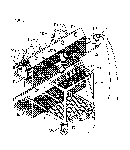
109401 Fig. 10 illustrates a fully loaded hand cart 100 configured with
upper and lower racks
115, 116 of a 2-bin variety. The upper rack 115 is loaded with a cable bag and
a standard reel-
in-box, while two cable bag wire containers 114 are loaded on the lower rack
116. Each of these
four wire containers 114 are feeding wire through payout slots 117 in the bins
and into the
dispensing cone 118 of the upper rack 115. From there, the wire may be pulled
in multiple
directions as needed. Provided the foot brake assembly 124 is engaged, the
cart 110 will rotate
freely in the direction of installation. In addition, wire reels have been
loaded on the front of the
cart, and mounted on a rod 162 fitted through holes 164 in the cart body 102.
While wire could
be installed and paid out from these reels, this is primarily used for storage
of spare wire reels of
wire awaiting loading into a box and bin 114. In all, the wire cart can
support up to two
thousand pounds of wire and equipment and function as described above.
100411 Accordingly, it has been described how the present invention
provides versatility,
flexibility and vast improvement over the prior art. In addition to its
various configurations, it
works to reduce line friction and increase the effective working distance for
the installers, while
reducing or eliminating the need to reposition the cart or change out wire
containers by sliding them
on and off a support rod. It will be understood by those skilled in the art
that various changes may
be made and equivalents may be substituted without departing from the scope of
the novel and non-
obvious techniques disclosed in this application. Therefore, it is intended
that the novel teachings of
the present invention not be limited to the particular embodiment disclosed,
but that they will
include all embodiments falling within the scope of the appended claims.
14