Note : Les descriptions sont présentées dans la langue officielle dans laquelle elles ont été soumises.
CA 02933020 2016-06-07
WO 2015/088759
PCT/US2014/067102
AIMING DEVICE FOR TARGETED DRILLING OF BONE
Inventors: Stefan WOLF and This AEBI
FIELD OF THE INVENTION
[00011 The present invention relates to the field of surgical
instruments. In particular,
the invention relates to an aiming device for targeted drilling into bone. The
invention
further relates to a positioning device for positioning the aiming device
relative to a bone
plate, and to a system for drilling into bone comprising an aiming device and
a
positioning device and, in particular, in combination with bone plates for the
left and
right femurs.
BACKGROUND
100021 Fractures are often stabilized through the fixation of a bone
plate fixed to the
bone by suitable fastening elements such as, for example, bone screws, pins,
etc. Holes
are often drilled into the subjacent bone to facilitate the insertion of
fixation elements
such as bone screws, pins and other implants. To guarantee secure fixation of
bone
fragments to each other and of the bone plate to the bone, the fixation
element must be
precisely positioned in the bone. In particular, the angles at which the
fixation element is
inserted into the bone are of great importance. For this reason, aiming
devices have been
used to more accurately target the drilling of these holes. Such an aiming
device may act
as a drilling template aligning drill sleeves along the desired drilling
paths. The aiming
device comprises through holes into which for example the drill sleeves can be
introduced and then a drilling instrument is guided through the drill sleeves
for targeted
drilling of screw holes. The drill sleeves are aligned with holes of a bone
plate via an
orientation of the through holes in the aiming device.
SUBSTITUTE SHEET (RULE 26)
CA 02933020 2016-06-07
WO 2015/088759
PCT/US2014/067102
100031 The present invention provides an improved aiming device for
targeted
drilling of holes into bone, and a corresponding positioning device for
positioning the
aiming device relative to a bone plate.
SUMMARY OF THE INVENTION
100041 According to a first aspect of the invention, at least one slot hole
extends
through the aiming device between a first surface facing a bone over which a
bone plate
and the aiming device are positioned, and an opposing second surface facing
away from
the bone. The slot hole is configured to receive therein a sleeve at different
locations
along a longitudinal extension thereof and at different angles relative to the
longitudinal
extension. The inclination of the angles may increase or decrease along the
longitudinal
extension. In one exemplary embodiment, the slot hole possesses mutually
opposing,
substantially parallel surfaces.
100051 Through the provision of a slot hole in the aiming device, it is
possible to vary
the angle at which a sleeve inserted through the slot hole extends through the
aiming
device or, more precisely, through the longitudinal extension of the slot
hole. The sleeve
is not fixed firmly in the slot hole, but can be shifted along the
longitudinal extension of
the slot hole to adjust the angle of inclination, with the angle increasing or
decreasing
along the longitudinal extension of the slot hole. In other words, the angle
of a sleeve
received in the slot hole can be increased by shifting the sleeve along the
longitudinal
extension of the slot hole, and may be reduced by shifting the sleeve in the
opposite
direction. Preferably, the angle may be increased or reduced by +15. This
permits a user
to choose, during a procedure, a desired angle at which a fixation element
will be inserted
into the bone.
[00061 According to an exemplary embodiment, an inner surface of the
slot hole
includes alignment structures that temporarily secure a sleeve received in the
slot hole at
any of a variety' of positions each of which corresponds to a predetermined
axis along
which a hole may be drilled. Each of the axes passes through the slot hole at
a different
2
SUBSTITUTE SHEET (RULE 26)
CA 02933020 2016-06-07
WO 2015/088759
PCT/US2014/067102
predetermined angle so that a user may select one of the predetermined angles
corresponding to a desired path of insertion of a bone fixation element. A
guide sleeve
may then be fixed in the chosen position to enable reliable targeted drilling
into the
subjacent bone.
100071 According to an exemplary embodiment, the alignment structure
comprises a
series of grooves formed in a side of the slot hole, each of the grooves
extending along an
axis corresponding to one the predetermined angles. Alternatively, the
alignment
structure may comprise a series of ribs extending into the slot hole with each
of the ribs
extending along an axis corresponding to one of the predetermined angles.
Those skilled
in the art will also understand that the alignment structure may comprise any
combination
of grooves and ribs desired or any other structure operable to maintain a
guide sleeve
inserted through the slot hole at a desired angle relative thereto. The
correspondence
between the individual features of the alignment structure and the desired
angles of
insertion through the slot hole provides a particularly precise fixation of a
sleeve
introduced in the slot hole. As will be described in greater detail below, the
sleeve
advantageously engages the alignment structure via a ratchet-like mechanism
enabling
movement of the sleeve through the slot hole until the sleeve reaches the
desired one of
the predetermined angles. The ratchet-like mechanism temporarily fixes the
sleeve at the
selected predetermined angle after which the sleeve may be more securely fixed
in
position as will be described below. Each of the individual features of the
alignment
structure preferably extends along a straight line parallel to one of the axes
along which a
hole may to be drilled. it will be appreciated an alternative alignment
structure may be
provided on the inner surface of the slot hole including different features or
any
combination of grooves, ribs and other features so long as these features
permit fixation
of a sleeve at any desired one of the predetermined angles within the slot
hole. For
example, such a structure may include knobs, arbitrary projections or
recesses. In one
exemplary embodiment, the shape of such these features of the alignment
structure
correspond to a shape of an outer surface of the sleeve.
3
SUBSTITUTE SHEET (RULE 26)
CA 02933020 2016-06-07
WO 2015/088759
PCT/US2014/067102
100081 According to one exemplary embodiment, axes of the alignment
structure
intersect at a common point at a selected distance from a bone-facing surface
of the
aiming device on the side of the bone-facing surface. Preferably, the common
point is in
proximity to a surface of the subjacent bone. In particular, the common point
may be
located in a through hole of a corresponding bone plate. This common point
forms a
center around which a sleeve received in the slot hole may be pivoted to vary
an angle of
the sleeve relative to the aiming device, and thus the introduction angle of a
fixation
element into the bone. While the sleeve is pivoted about the common point, it
is shifted
along the longitudinal extension of the slot hole, with the angle between the
sleeve and
the longitudinal extension of the slot hole increasing or decreasing.
[00091 According to one exemplary embodiment, the aiming device is
formed .mirror-
symmetrically (e.g., symmetrically about a center plane extending through the
aiming
device parallel to and between first and second surfaces thereof). In
particular, the entire
aiming device may be formed mirror-symmetrically, preferably with regard to a
center
plane extending parallel to the first and second surfaces and dividing the
aiming device
between the first and second surfaces into two mirror-inverted halves. In
another
exemplary embodiment, only the slot hole may be formed mirror-symmetrically.
Through the mirror-symmetric configuration it is possible to employ one and
the same
aiming device for both the right and left body halves of a patient. For
example, a single
aiming device may be employed with a bone plate for a patient's right proximal
femur
and then rotated 180 degrees for use on the left proximal femur.
[00101 According to one exemplary embodiment, the slot hole has an
hourglass-like
or waisted cross section in a plane perpendicular to the first and second
surfaces and
transverse to the longitudinal extension of the slot hole. As described above,
the slot hole
may be formed symmetrically. The hourglass-like waisted cross section allows a
sleeve
to be introduced into the slot hole at an oblique incline, in the transverse
direction of the
slot hole. For example, the sleeve may be introduced into the slot hole
obliquely from
the mutually opposing surfaces of the aiming device such that the sleeve
engages a
4
SUBSTITUTE SHEET (RULE 26)
CA 02933020 2016-06-07
WO 2015/088759
PCT/US2014/067102
portion of the inner surface of the slot hole. In an exemplary embodiment the
sleeve
engages one or more surfaces of the alignment structure extending around no
more than
half of the circumference of the sleeve. The sleeve may engage one side of the
slot hole
only such as, for example, an upper region of the inner surface of the slot
hole and on an
opposing side of the slot hole only with a lower region of the inner surface
of the slot
hole. Thus, the structure may comprise on the inner surface of the slot hole
two mutually
independent regions for a laterally reversed application of the aiming device.
The two
mutually independent regions may be formed by non-contiguous portions of the
inner
surface of the slot hole, the first region extending from the first surface of
the aiming
device toward the center plane of the aiming device and the second region
extending
from the second surface of the aiming device toward the center plane.
[00111 A slot hole having the above-described hourglass-like cross
section may,
according to one exemplary embodiment, be formed by two mutually superimposed
slot
holes extending parallel to each other and inclined transversely to their
longitudinal
extension in different directions. The two mutually superimposed slot holes
may be
formed mirror-symmetrically with regard to a plane extending between the first
and
second surfaces (e.g., symmetrically about the center plane). This allows a
laterally
reversed employment of the aiming device, for example for employment with the
left
femur and alternatively with the right femur, because a sleeve can be
introduced into the
respective slot hole accordingly from both sides of the aiming device.
100121 According to a further exemplary embodiment, the aiming device
has a first
elongate portion in which the slot hole is arranged, and a second elongate
portion in
which a plurality of through holes are arranged. The plurality of through
holes may be
substantially cylindrical and extend through the aiming device perpendicular
to a
longitudinal axis of the aiming device from the first to the second surface of
the aiming
device. The through holes may overlap one another as would be understood by
those
skilled in the art.
5
SUBSTITUTE SHEET (RULE 26)
CA 02933020 2016-06-07
WO 2015/088759
PCT/US2014/067102
100131 In one exemplary embodiment, the first and second elongate
portions extend
side by side. Each of the two elongate portions of the aiming device may
extend between
respective proximal and distal ends, with the proximal ends of the first and
second
elongate portions being interconnected to one another. The distal ends may be
free (i.e.,
not connected to one another) or likewise interconnected. It will be
appreciated that the
first and second elongate portions may also be arranged side by side
interconnected along
all or any part of total lengths. In one exemplary embodiment, a length of the
first
elongate portion having the slot hole is shorter than the second elongate
portion including
the plurality of through holes. In another exemplary embodiment, the first and
second
portions may be equally long, or the second portion may be longer than the
first portion.
The slot hole may occupy substantially the total length of the first elongate
portion. The
plurality of through holes may be distributed substantially along the total
length of the
second elongate portion. In one exemplary embodiment the through holes may be
distributed along the length of the second elongate portion at regular
intervals.
[00141 In one exemplary embodiment, the first elongate portion is
substantially
straight while the second elongate portion extends along a curve such as an
arc. The
curved shape may correspond to a curve of a bone plate with which the aiming
device is
to be aligned, such as, for example, a bone plate for treating the human
femur. In
particular, it will be appreciated that the through holes may be arranged to
correspond to
an arrangement of through holes of the bone plate.
100151 According to a further exemplary embodiment, the aiming device
further
includes at least one further through hole extending through a portion of the
aiming
device between the slot hole and the plurality of through holes. The at least
one further
through hole extends along a hole axis extending through the aiming device
obliquely
with regard to the first and second surfaces of the aiming device. In
particular in the
event that the aiming device is intended for employment with a bone plate for
the human
proximal femur, the at least one further through hole may be arranged in a
proximal
6
SUBSTITUTE SHEET (RULE 26)
CA 02933020 2016-06-07
WO 2015/088759
PCT/US2014/067102
portion of the aiming device to guide bone screws into the femoral neck or,
where
applicable, to guide periprosthetic bone screws,
[00161 According to a further aspect of the invention, a positioning
device is provided
for positioning the aiming device relative to a bone plate. A base of the
positioning
device has a first side and an opposing second side. The surface of the first
side is shaped
to be adjoined to a bone plate and may, for this purpose, be non-planar,
curved, bulged or
wavy as would be understood by those skilled in the art. On the opposing
second side,
i.e., on a base side facing away from the bone, the aiming device may be
coupled thereto.
The base includes a guide hole extending therethrough from the first to the
second side,
formed as a slot hole and configured to receive a sleeve, namely the sleeve
inserted
through the slot hole of the aiming device, at different angles. The term
"slot hole," as
used herein, refers to an elongated hole having a longitudinal extension
greater than its
transverse extension. In other words, the guide hole does not have a circular
cross
section and is not cylindrical.
[00171 According to an exemplary embodiment, the guide hole tapers in the
direction
of the first side of the base facing the bone plate. The guide hole may be,
for example,
funnel shaped. This shape allows a sleeve introduced into the guide hole to
be, for
example, pivoted within the guide hole to be positioned at a desired angle
with respect to
the positioning device.
100181 According to one exemplary embodiment, the guide hole in the base of
the
positioning device has at least one planar inner wall. Preferably, the guide
hole will have
two mutually opposing planar inner walls parallel to each other. A sleeve
received in the
guide hole, which can serve e.g. as a guide sleeve for a drill or for a drill
sleeve, may thus
be guided through the guide hole along the one planar inner wall or the two
planar inner
walls in a defined plane. The longitudinal extension of the slot hole of the
aiming device
may also extend in this plane when it is connected to the positioning device.
SUBSTITUTE SHEET (RULE 26)
CA 02933020 2016-06-07
WO 2015/088759
PCT/US2014/067102
100191 According to one exemplary embodiment, the positioning device
includes a
leg extending away from the base on the second side. An aiming device coupling
is
formed on the leg, preferably on its free end. A length of the leg corresponds
to a
distance between the aiming device and the positioning device, facilitating
the alignment
of the guide sleeve at a particular desired angle with respect to the aiming
device.
100201 A further exemplary embodiment includes a fastening element
protruding
from the base of the positioning device on the first side. The fastening
element is
rotatable relative to the base to fasten the positioning device to a bone
plate. The
fastening element may be, for example, a screw, such as a knurled-head screw,
which
may be screwed into a correspondingly threaded hole in the bone plate.
However, other
fastening elements may also be provided such as, for example, a bayonet lock
or the like.
In one exemplary embodiment, the positioning device may be releasably
coupleable to
the bone plate so that the positioning device may be removed after fixation of
the bone
plate on the bone.
100211 A further aspect of the invention provides a system for drilling a
hole into
bone having an aiming device and a positioning device as described above. The
system
according to an exemplary embodiment comprises the above-mentioned sleeve
which
preferably possesses a cylindrical outer circumference. The cylindrical sleeve
serves as a
guide sleeve for a drill or for other tools, e.g. for a drill sleeve. The
sleeve is adapted to
extend through the slot hole of the aiming device and the guide hole of the
positioning
device to engage the slot hole and the guide hole. The sleeve may be
positioned within
the slot hole at any of a variety of predetermined angles relative to the
longitudinal
extension of the slot hole of the aiming device and to the positioning device,
in one
exemplary embodiment, the sleeve may be a slotted sleeve ¨ e.g., the sleeve
possesses at
least one slot in the longitudinal direction of the sleeve, the slot
preferably extending
substantially parallel to a longitudinal axis of the sleeve - so that the
sleeve is radially
compressible.
8
SUBSTITUTE SHEET (RULE 26)
CA 02933020 2016-06-07
WO 2015/088759
PCT/US2014/067102
100221 According to a further exemplary embodiment, the system further
comprises a
drill sleeve which serves e.g. to guide a drill or other tool, the drill
sleeve having an outer
diameter corresponding to an inner diameter of the slotted sleeve so that the
drill sleeve
may be inserted into the slotted sleeve. The angle of the slotted sleeve
relative to the
longitudinal extension of the slot hole of the aiming device is variable when
the slotted
sleeve is compressed radially, and fixed when the drill sleeve has been
inserted into the
slotted sleeve. Since the outer diameter of the drill sleeve corresponds to
the inner
diameter of the slotted sleeve when the slotted sleeve is not in a compressed
configuration, introduction of the drill sleeve into the slotted sleeve
prevents the slotted
sleeve from being compressed and fixes the slotted sleeve in a desired
position within the
slot hole. For this purpose, the outer diameter of the slotted sleeve is
accordingly adapted
to the slot hole. Upon a shift of the slotted sleeve within the slot hole
along the
longitudinal extension of the slot hole, a ratchet operation may be performed
by the
aligning structure on the inner surface of the slot hole. As soon as the drill
sleeve has
been introduced into the slotted guide sleeve, radial compression of the guide
sleeve is
prevented to the extent that the guide sleeve engages the aligning structure
on the inner
surface of the slot hole such that the slotted guide sleeve is fixed in the
slot hole at a
predetermined angle. Secure fixation of the slotted sleeve in the slot hole
can thus be
created in a simple manner without any further fastening elements, with the
angular
position being predetermined by the aligning structure of the inner surface of
the slot
hole, in particular, by grooves and/or ribs formed therein.
100231 According to a further exemplary embodiment, the positioning
device has an
aiming device coupling, and the aiming device includes a positioning device
coupling,
which have mutually complementary surfaces. The aiming device coupling and the
positioning device coupling may be configured to enable mounting of the aiming
device
on the positioning device in only one orientation to prevent incorrect
coupling. For
example, the positioning device coupling may have a coupling axis, with at
least one of
the positioning device coupling and the aiming device coupling being
asymmetrical with
regard to a plane through the coupling axis so that upon employment of the
system for
9
SUBSTITUTE SHEET (RULE 26)
CA 02933020 2016-06-07
WO 2015/088759
PCT/US2014/067102
one of the left and right body halves of a patient, only one respective
correct orientation
of the aiming device can be obtained. However, identical coupling structures
may be
provided on the sides of the first and second surfaces of the aiming device,
so that the
same aiming device may be employed with a corresponding positioning device for
different bone plates, e.g. for the left femur and the right femur.
[0024] According to a further exemplary embodiment, the system provides
two
positioning devices mirror-inverted relative to each other (e.g., mirror
images of one
another), to enable the fastening of the aiming device to a bone plate for the
right
proximal femur by means of the one positioning device and for the left
proximal femur
by means of the mirror-inverted positioning device. The aiming device is
preferably
mirror-symmetric, as described above, and may be employed with both
positioning
devices by simply turning the aiming device around (e.g., rotating the aiming
device
approximately 180' about the longitudinal axis thereof), when it is to be used
for the
patient's other body half. The aiming device and the two positioning devices
may be
supplied in a kit, which may also comprise the slotted guide sleeve and one or
a plurality
of different drill sleeves.
BRIEF DESCRIPTION
[0025] The preceding summary of the invention as well as the following
description
of an exemplary embodiment will become more easily understandable in the light
of the
attached drawings. An exemplary embodiment of the invention will be described
hereinafter with reference to the accompanying drawings. It will be
appreciated,
however, that the application is not limited to the exemplary embodiment
shown. The
drawings show:
Fig. 1 shows a perspective view of an aiming device which is mounted on a bone
plate by means of a positioning device, according to an exemplary embodiment
of the
present invention;
Fig. 2 shows a perspective view of the aiming device of Fig. 1;
SUBSTITUTE SHEET (RULE 26)
CA 02933020 2016-06-07
WO 2015/088759
PCT/US2014/067102
Fig. 3 shows another perspective view of the aiming device of Fig, 1;
Fig. 4 shows a top plan view of the aiming device of Fig. 1;
Fig. 5 shows a bottom plan view of the aiming device of Fig. 1;
Fig, 6 shows a side view of the aiming device of Fig. 1;
Fig. 7 shows another side view of the aiming device of Fig. 1;
Fig. 8 shows a perspective view of the positioning device of Fig. 1;
Fig. 9 shows a side view of the positioning device of Fig. 1;
Fig. 10 shows a top plan view of the positioning device of Fig. 1;
Fig, 11 shows a perspective view of a positioning device according to another
exemplary embodiment of the present invention;
Fig. 12 shows a side view of the positioning device of Fig. 11;
Fig. 13 shows a top plan view of the positioning device of Fig. 11;
Fig. 14a shows a first plan view of a positioning device coupling of the
aiming
device of Fig. 1;
Fig, 14b shows a plan view an aiming device coupling of the positioning device
of
Figs. 8¨ 10;
Fig. 15a shows a second plan view of the positioning device coupling of the
aiming
device of Fig. 1;
Fig. 15b shows a plan view of an aiming device coupling of the positioning
device
of Figs. 11 13;
11
SUBSTITUTE SHEET (RULE 26)
CA 02933020 2016-06-07
WO 2015/088759
PCT/US2014/067102
Fig. 16 shows a cross-sectional view of the positioning device coupling of the
aiming device of Fig, 1; and
Fig. 17 shows a perspective view of the slotted guide sleeve of Fig. 1.
DETAILED DESCRIPTION
[0026] The present invention may be further understood with reference to
the
following description and the appended drawings, wherein like elements are
referred to
with the same reference numerals. The exemplary embodiments relate to an
aiming
device for a targeted drilling of a hole into a bone. The exemplary
embodiments also
relate to a positioning device for positioning the aiming device in a desired
position
relative to a bone plate. Although the exemplary embodiments describe an
aiming device
and positioning device for the targeted drilling of a hole into a proximal
femur, it will be
understood by those of skill in the art that the aiming device and positioning
device of the
present invention may be similarly utilized for the targeted drilling of any
long bone.
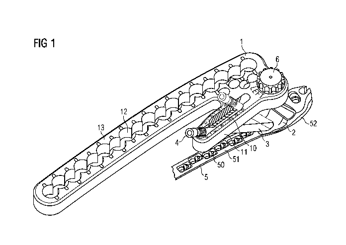
100271 As shown in Fig. 1, an aiming device I may be mounted on a bone
plate 5 by
means of a positioning device 2. The aiming device 1 is aligned with the bone
plate 5 in a
predetermined configuration via the positioning device 2, so that the aiming
device 1 can
be employed for targeted drilling of holes into a bone over which the bone
plate 5 is
positioned. A cylindrical guide sleeve 3 may be inserted into a slot hole 10
of the aiming
device 1 to guide a drill sleeve 4 therethrough. The angle of the guide sleeve
3, and
thereby the drill sleeve 4, relative to the aiming device I and the
positioning device 2
may be adjusted. A fastening element 6 such as, for example, a knurled-head
screw, may
be used to fix the aiming device I relative to the positioning device 2.
100281 The bone plate 5 (only partially shown) may be a bone plate for a
patient's left
proximal femur. As will be described in further detail below, the same aiming
device 1
may also be utilized with a bone plate for a patient's right proximal femur by
using a
positioning device 2' configured for the right proximal femur. The bone plate
5
comprises a head portion 52 at a proximal end of the bone plate 5 as well as a
shaft
12
SUBSTITUTE SHEET (RULE 26)
CA 02933020 2016-06-07
WO 2015/088759
PCT/US2014/067102
portion 51 extending therefrom in the direction of a distal end of the bone
plate 5. The
head portion 52 as well as the shaft portion 51 have through holes extending
therethrough
for receiving fixation elements such as bone screws with which the bone plate
5 may be
fixed over the bone. The through holes 50 in the shaft portion 51 of the bone
plate 5 may
be formed as, for example, combination holes which have a compression portion
and a
variable-angle locking portion. The through holes in the proximal head portion
52 are
hidden by the positioning device 2 in Fig. 1,
[00291 As shown in Figs, 2-7, the aiming device 1 may be configured as
an aiming
arm which, in an exemplary embodiment, includes a first elongate portion 11
and a
second elongate portion 13. The aiming device I further includes a first
surface 16 and a
second surface 17, with either the surface 16 or the surface 17 facing the
subjacent bone
depending on the application. The first elongate portion 11 includes a slot
hole 10
extending therethrough from the first surface 16 to the second surface 17 for
receiving
the guide sleeve 3 with the drill sleeve 4. The second elongate portion 13
includes a
plurality of substantially cylindrical through holes 12 extending therethrough
from the
first surface 16 to the second surface 17. When the aiming device 1 is mounted
to the
bone plate 5, the cylindrical through holes 12 are aligned with the through
holes 50 of the
shaft portion 51 of the bone plate 5 so that a drill sleeve inserted through
the through
holes 12 may be used to drill a hole into the bone in alignment with the
through holes 50
of the bone plate 5. The aiming device 1 may further include a positioning
device
coupling 15 for connecting the aiming device 1 to a positioning device 2, as
will be
described in greater detail below.
[00301 As shown in Fig. 1 via a dashed representation of a guide sleeve,
the guide
sleeve 3 may be received in the slot hole 10 of the aiming device 1 at a
plurality of
discrete angles relative to the aiming device 1. As the guide sleeve 4 is
inserted into the
slot hole 10, the guide sleeve 3 is passed through a guide hole 22 (see Fig.
10) of the
positioning device 2, which is also formed as a slot hole, so that the guide
sleeve 3 may
be moved within the guide hole 22. In an exemplary embodiment, the guide
sleeve 3
13
SUBSTITUTE SHEET (RULE 26)
CA 02933020 2016-06-07
WO 2015/088759
PCT/US2014/067102
may be used for the targeted drilling of a hole for a ealear screw to be
introduced into the
calcar femorale of a femur.
[00311 As shown in Figs. 2 - 5, the slot hole 10 may be defined via
alignment
structures 34, 35 extending along an inner surface thereof. The alignment
structures 34,
35 may be formed along, for example, opposing inner surfaces, respectively, of
the slot
hole 10. Preferably, the alignment structures 34, 35 comprise grooves or ribs
extending
into the slot hole 10 along axes extending in the direction of predetermined
angles along
which the guide sleeve 3 is to be aligned. In a further exemplary embodiment,
the axes
of each of the alignment structures 34, 35 intersect at a common point located
at a
distance from the aiming device 1 on the side of the surface 17 or of the
surface 16 facing
the bone. In particular, the common point may be located, when the aiming
device 1 is
mounted to the bone plate 5, near the bone surface under the guide hole 22 or
in the guide
hole 22 of the positioning device 2. Where the axes of the alignment
structures 34, 35
intersect at a common point, a guide sleeve 3 inserted into the slot hole 10
may be moved
along the longitudinal extension of the slot hole 10 by pivoting the guide
sleeve about the
common point. The axes of the alignment structures 34, 35, however, are not
required to
intersect at a common point. Axes of the alignment structures 34, 35 extend
along the
inner surface of the slot hole 10 to correspond to a desired direction of the
guide sleeve 3
to be received in the slot hole 10 and the guide hole 22.
[00321 The guide sleeve 3 is sized and shaped to form a ratchet mechanism
together
with the alignment structures 34, 35 on the inner surface of the slot hole 10.
The guide
sleeve 3 snaps into place at any of the predetermined angles relative to the
aiming device
1 defined by the alignment structures 34, 35. As shown in Fig. 17, the guide
sleeve 3
includes axial slots 30 making the guide sleeve 3 radially compressible so
that the guide
sleeve 3 may be compressed as it passes between projections of the alignment
structures
34, 35 and then expands to snap into place within expanded portions of the
slot hole 10
corresponding to each of the desired angles so that the guide sleeve 3 moves
between and
is held discrete positions within the slot hole 10 in a ratchet-like manner. A
distal end 33
14
SUBSTITUTE SHEET (RULE 26)
CA 02933020 2016-06-07
WO 2015/088759
PCT/US2014/067102
of the guide sleeve 3 is passed through the slot hole 10 and into the guide
hole 22 of the
positioning device 2, so that the slots 30 are positioned in the region of the
slot hole 10 of
the aiming device 1. A surgeon or other user may then shift the guide sleeve 3
within the
slot hole 10 in the manner of a ratchet. An outer diameter of the drill sleeve
4 is selected
to conform to an expanded inner diameter of the guide sleeve 3 so that, when
the drill
sleeve 4 is introduced into the guide sleeve 3, the guide sleeve 3 is fixed in
the slot hole
at a desired location and angle as the guide sleeve 3 can no longer be
radially
eompresded to move between projections of the alignment structures 34, 35. As
shown
in Fig, 6, and indicated by a scale 38, the angle between the guide sleeve 3
and the
10 longitudinal extension of the slot hole 10 may be varied by up to 150.
It will be
understood by those of skill in the art, however, that the slot hole 10 may
also have a
greater angle variability of up to 20' or up to 25 or even up to 30 , with
the stated angles
preferably beginning at 00 with respect to a vertical axis extending
perpendicularly
relative to the two aiming device surfaces 16, 17 but, where applicable, also
at a negative
angle, e.g. -5 or -100.
[00331 As is evident from Figs. 2 to 7, the aiming device 1 is may be
made mirror-
symmetric with regard to a center plane extending between the first surface 16
and
second surface 17. In other words, the aiming device 1 is symmetrical about
the center
plane, which extends parallel to and between the first and second surface 16,
17. In this
way, the aiming device 1 may be employed with bone plates for the left
proximal femur
as well as with bone plates for the right proximal femur by simply rotating
the aiming
device 1 180' about a longitudinal axis thereof and mounting the aiming device
1 to the
bone plate using a corresponding one of the positioning devices 2, 2'. In
particular, the
slot hole 10 of such an embodiment is mirror-symmetrical with regard to the
center plane.
Thus, the slot hole 10 is formed by two superimposed slot holes, so that a
guide sleeve 3
can be guided through the aiming device I and introduced into a corresponding
guide
hole 22, 22' of the positioning device 2, 2' from the first surface 16 as well
as from the
opposing surface 17,
SUBSTITUTE SHEET (RULE 26)
CA 02933020 2016-06-07
WO 2015/088759
PCT/US2014/067102
[00341 Referring to Figs. 1 to 5, the alignment structures 34, 35 on the
inner surface
of the slot hole 10 comprise two mutually independent regions 34a, 34b and
35a, 35b.
This means that substantially only the region 34a, 34b engage a guide sleeve 3
during
employment of the aiming device 1 from one side, While the guide sleeve 3 is
engaged
substantially only with the region 35a, 35b of the alignment structures 34, 35
upon the
mirror-inverted employment of the aiming device 1. The regions 34a, 34b of the
alignment structure preferably occupy substantially half of the inner surface
of the slot
hole 10 while the regions 34b, 35b occupy the other half. In other words, a
point
separating the regions 34a and 34b from the regions 35a and 35b is
substantially
equidistant from each of the first and second surfaces 16, 17. The region 34a,
34b
comprises a portion 34a which extends from the surface 16 of the aiming device
1 in the
direction of the center plane, and a portion 34b on an opposing side with
regard to the
transverse extension of the slot hole 10, which extends from the center plane
to the
surface 17 of the aiming device 1. These two portions 34a, 34b of the
structure are not
contiguous, but are symmetrical about the center plane such that a guide
sleeve 3
received in the slot hole 10 engages the one portion 34a of the structure 34on
the one side
of the slot hole 10, and the other portion 34b of the structure on the other
side of the slot
hole 10. The same holds for the region 35a, 35b of the structure 35 when the
aiming
device 1 is employed the other way round. Because the guide sleeve 3 is
movable in a
plane inclined with regard to the aiming device 1, it is possible to provide
two mutually
independent regions 34a, 34b and 35a, 35b of the structure on the inner
surface of the slot
hole 10 which allow the laterally reversed application of the aiming device 1.
The
formed slot hole 10 may thus have an hourglass-like cross section when viewed
in a
plane perpendicular to the surfaces 16, 17 of the aiming device 1.
[00351 As mentioned above, the aiming device 1 comprises a first elongate
portion 11
and a second elongate portion 13. The first elongate portion 11 has a proximal
end 37
and a distal end 36. The second elongate portion 13 has a proximal end 19 and
a distal
end 18. The two elongate portions 11, 13 may be interconnected at their
proximal ends
37, 19. In an exemplary embodiment, the distal ends 36, 18 are free ¨ i.e.,
the distal ends
16
SUBSTITUTE SHEET (RULE 26)
CA 02933020 2016-06-07
WO 2015/088759
PCT/US2014/067102
36, 18 are not directly connected to one another. The two elongate portions
11, 13 may
extend side by side along the longitudinal axis of the aiming device 1 and, in
one
exemplary embodiment, extend substantially parallel to one another along a
common
plane.
100361 The aiming device I may further include through holes 14 extending
obliquely
therethrough from the first surface 16 to the second surface 17. The through
holes 14
may extend through a portion of the aiming device 1. connecting the proximal
ends 37, 19
of the first and second elongate portions 11, 13, respectively. The through
holes 14 may
be, for example, sized and shaped to receive drill sleeves for targeted
drilling of holes for
placing bone screws within a proximal portion of the femur, in particular, the
femoral
neck.
100371 Figs. 8 to 10 show the positioning device 2 configured for
employment with
the bone plate 5 for a left proximal femur, as represented in Fig. 1. Figs. 11
to 1.3 show a
positioning device 2' configured for employment with a bone plate for a right
proximal
femur. Positioning device 2, 2' may be mirror-inverted relative to one another
¨ e.g.,
mirror images of one another.
[00381 The positioning device 2 for a bone plate for the left proximal
femur possesses
a base 20 having a surface 23 adjoining the bone plate 5 during use and is
accordingly
contoured. In other words, the surface 23 is not planar, but e.g. bulged,
curved or wavy
in accordance with a shape of the bone plate 5. A leg 21 extends from an
opposing side
24 of the base 20 and includes an aiming device coupling 25 at an end thereof.
A length
of the leg 21 corresponds to a desired distance of the aiming device I from
the bone plate
5, over which distance the guide sleeve 3 extends. The positioning device 2
may be
fastened to the bone plate 5 via, for example, a screw 26 which protrudes from
the
surface 23, to engage a correspondingly threaded hole of the bone plate 5. It
will be
appreciated that other fastening elements are also possible for fastening the
positioning
device 2 to a bone plate, such as for example a bayonet lock or the like.
17
SUBSTITUTE SHEET (RULE 26)
CA 02933020 2016-06-07
WO 2015/088759
PCT/US2014/067102
100391 As shown in Fig. 10, the guide hole 22 in the base 20 of the
positioning device
2 may be formed as a slot hole. In other words, the guide hole 22 does not
have a
circular cross section, but is elongated along a longitudinal axis thereof
i.e., a
longitudinal extension of the guide hole is greater than its transverse
extension. As
explained above in connection with the aiming device 1, the guide sleeve 3 is
introduced
with its distal end 33 into the guide hole 22 and is movable therewithin due
to the shape
of the guide hole 22. By moving the guide sleeve 3 within the guide hole 22,
the angle
between the base 20 and the guide sleeve 3 may be varied. In particular, since
the guide
sleeve 3 may be moved within the slot hole 10 of the aiming device 1 in a
ratchet-like
fashion within a plane extending substantially perpendicularly through the
first and
second surfaces 16, 17 and between opposing inner surfaces of the slot hole
10, the guide
hole 22 has at least one, and, as in this embodiment, preferably two, planar
inner wails
along which the guide sleeve 3 is movable.
100401 The same holds for the mirror-inverted positioning device 2'. The
positioning
device 2' for a bone plate for the right proximal femur possesses a base 20'
having a
surface 23' which adjoins the bone plate during use and is accordingly
contoured. In
other words, the surface 23' is not planar, but e.g. bulged, curved or wavy in
accordance
with a shape of the bone plate. A leg 21' extends from an opposing side 24' of
the base
20' and includes an aiming device coupling 25' at an end thereof. A length of
the leg 21'
corresponds to a distance of the aiming device I from the bone plate 5, over
which
distance the guide sleeve 3 extends. The positioning device 2' may be fastened
to the
bone plate via, for example, a screw 26' which protrudes from the surface 23'
to engage a
correspondingly threaded hole of the bone plate5. It will be appreciated that
other
fastening elements are also possible for fastening the positioning device 2
to a bone
plate, such as for example a bayonet lock or the like.
[00411 As shown in Fig, 13, the guide hole 22' in the base 20' of the
positioning
device 2' may be formed as a slot hole, meaning that it does not have a
circular cross
section, but is an elongated hole having a longitudinal extension greater than
its
18
SUBSTITUTE SHEET (RULE 26)
CA 02933020 2016-06-07
WO 2015/088759
PCT/US2014/067102
transverse extension. As explained above in connection with the aiming device
1, the
guide sleeve 3 is introduced with its distal end 33 into the guide hole 22'
and is movable
therewithin due to the shape of the guide hole 22. By moving the guide sleeve
3 within
the guide hole 22', the angle between the base 20' and the guide sleeve 3 may
be varied.
In particular since the guide sleeve 3 through the slot hole 10 of the aiming
device 1 is
movable in a plane extending substantially perpendicularly relative to the
first and second
surfaces 16, 17 and between opposing inner surface of the slot hole 10, the
guide hole 22'
has again at least one planar inner wall along which the guide sleeve 3 is
movable.
[00421 Fig. 14a shows the first surface 16 of the aiming device 1 to
illustrate a portion
of a positioning device coupling 15 for use in, for example, a left side
configuration. As
shown in Fig. 14a, the aiming device 1 includes the positioning device
coupling 15
which, in an exemplary embodiment, comprises an insert 40 insertable into an
opening of
the aiming device 1. In an exemplary embodiment, the insert 40 is formed of a
metal,
whereas the aiming device 1 is preferably formed of a plastic, e.g. PEEK.
However, the
insert 40 may also be formed through a portion of the positioning device 2
formed
integrally therewith. The positioning device coupling 15 is formed such that
the
positioning device 2 is fixable only in a desired orientation. In particular,
this prevents
the aiming device 1 from being mounted on the positioning device 2' intended
for a
patient's right body half in an orientation intended for the left body half,
and vice versa.
Preferably, the positioning device coupling 15 is for this purpose asymmetric
with regard
to a plane through a coupling axis which, in an exemplary embodiment, extends
through
the insert 40 perpendicularly to the surfaces 16, 17 of the aiming device 1.
For this
purpose, a pin 45 or other adjusting element protrudes into the opening of the
insert 40 to
engage a corresponding recess 44 of an aiming device coupling 25 of the
positioning
device 2 and prevent an incorrect mounting. For further precise alignment of
the aiming
device 1 with regard to the positioning device 2, the positioning device
coupling 15
comprises recesses 41 which engage a pin 43 of the aiming device coupling 25
here (see
14b), Through tightening of the knurled-head screw 6 engaging a threaded hole
on
the face of the aiming device coupling 25, the pin 43 is drawn into the
recesses 41, and
19
SUBSTITUTE SHEET (RULE 26)
CA 02933020 2016-06-07
WO 2015/088759
PCT/US2014/067102
the aiming device 1 is fixed in the correct orientation. The axis of the pin
45 and the axis
of the recesses 41 may be mutually offset (for example by 35 ). The pin 45
preferably
protrudes through the body of the aiming device I and through the insert 40,
so that the
insert 40 is secured against unintended rotation relative to the body of the
aiming device
1. It will be appreciated that other configurations of the aiming device
coupling 25 and
of the positioning device coupling 15 are possible, so long as the coupling
couplings
provide the described keyed alignment.
[00431 Fig. 15a shows the aiming device 1 from the opposing side 17 of
the aiming
device I to illustrate a portion of the positioning device coupling 15 for use
in, for
example, the right side configuration. The insert 40 has on this side,
corresponding
recesses 42 which engage the pin 43 of the aiming device coupling 25' of the
positioning
device 2' (see Fig. 15b). Otherwise, the remarks made in connection with Figs,
14a, 14b
apply accordingly.
[00441 Thus, according to one exemplary embodiment of the present
invention, a
system comprises a positioning device 2 for the left side and a mirror-
inverted
positioning device 2' for the right side, but only one aiming device I., which
is formed
mirror-symmetrically (i.e., symmetrically about a center plane) to be utilized
with both
positioning devices 2, 2' by being rotated 180 about a longitudinal axis
thereof.
100451 Although the preferred embodiment was described with reference to
a patient's
left or right proximal femur, it will be understood by those of skill in the
art that the
principle of the invention may also be applied to aiming devices and
positioning devices
for other bones. For example, the described system may also be utilized for
the distal
femur, the tibia or other long bones. It will be appreciated that the shape
and
dimensioning of the aiming device and of the positioning device can be adapted
in
accordance with the case of application without impairing the principle of the
invention.
100461 It will be apparent to those skilled in the art that various
modifications and
variations may be made in the structure and the methodology of the present
invention,
SUBSTITUTE SHEET (RULE 26)
CA 02933020 2016-06-07
WO 2015/088759
PCT/US2014/067102
without departing from the spirit or scope of the invention. Thus, it is
intended that the
present invention cover the modifications and variations of the invention
provided that
they come within the scope of the appended claims and their equivalents.
21
SUBSTITUTE SHEET (RULE 26)