Une partie des informations de ce site Web a été fournie par des sources externes. Le gouvernement du Canada n'assume aucune responsabilité concernant la précision, l'actualité ou la fiabilité des informations fournies par les sources externes. Les utilisateurs qui désirent employer cette information devraient consulter directement la source des informations. Le contenu fourni par les sources externes n'est pas assujetti aux exigences sur les langues officielles, la protection des renseignements personnels et l'accessibilité.
L'apparition de différences dans le texte et l'image des Revendications et de l'Abrégé dépend du moment auquel le document est publié. Les textes des Revendications et de l'Abrégé sont affichés :
| (12) Demande de brevet: | (11) CA 2935757 |
|---|---|
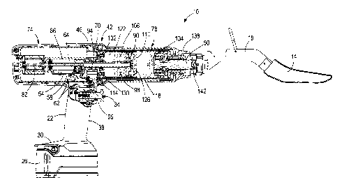
| (54) Titre français: | OUTIL IMPACTEUR MEDICAL |
| (54) Titre anglais: | MEDICAL IMPACTOR TOOL |
| Statut: | Réputée abandonnée |
| (51) Classification internationale des brevets (CIB): |
|
|---|---|
| (72) Inventeurs : |
|
| (73) Titulaires : |
|
| (71) Demandeurs : |
|
| (74) Agent: | MARKS & CLERK |
| (74) Co-agent: | |
| (45) Délivré: | |
| (22) Date de dépôt: | 2016-07-11 |
| (41) Mise à la disponibilité du public: | 2017-01-22 |
| Requête d'examen: | 2021-06-25 |
| Licence disponible: | S.O. |
| Cédé au domaine public: | S.O. |
| (25) Langue des documents déposés: | Anglais |
| Traité de coopération en matière de brevets (PCT): | Non |
|---|
| (30) Données de priorité de la demande: | ||||||
|---|---|---|---|---|---|---|
|
A power tool includes an output member, a drive mechanism operable to perform
work
on the output member in one of a first mode or a second mode, and an actuator
for activating the
drive mechanism in the first mode or the second mode based upon an amount of
time the
actuator is depressed.
Note : Les revendications sont présentées dans la langue officielle dans laquelle elles ont été soumises.
Note : Les descriptions sont présentées dans la langue officielle dans laquelle elles ont été soumises.
2024-08-01 : Dans le cadre de la transition vers les Brevets de nouvelle génération (BNG), la base de données sur les brevets canadiens (BDBC) contient désormais un Historique d'événement plus détaillé, qui reproduit le Journal des événements de notre nouvelle solution interne.
Veuillez noter que les événements débutant par « Inactive : » se réfèrent à des événements qui ne sont plus utilisés dans notre nouvelle solution interne.
Pour une meilleure compréhension de l'état de la demande ou brevet qui figure sur cette page, la rubrique Mise en garde , et les descriptions de Brevet , Historique d'événement , Taxes périodiques et Historique des paiements devraient être consultées.
| Description | Date |
|---|---|
| Réputée abandonnée - les conditions pour l'octroi - jugée non conforme | 2024-09-09 |
| Lettre envoyée | 2024-03-14 |
| Un avis d'acceptation est envoyé | 2024-03-14 |
| Inactive : Approuvée aux fins d'acceptation (AFA) | 2024-03-07 |
| Inactive : Q2 réussi | 2024-03-07 |
| Modification reçue - modification volontaire | 2023-07-21 |
| Modification reçue - réponse à une demande de l'examinateur | 2023-07-21 |
| Rapport d'examen | 2023-03-23 |
| Inactive : Rapport - CQ réussi | 2023-03-23 |
| Modification reçue - modification volontaire | 2023-03-02 |
| Modification reçue - réponse à une demande de l'examinateur | 2023-03-02 |
| Rapport d'examen | 2022-11-04 |
| Inactive : Rapport - Aucun CQ | 2022-10-19 |
| Lettre envoyée | 2021-07-09 |
| Requête d'examen reçue | 2021-06-25 |
| Exigences pour une requête d'examen - jugée conforme | 2021-06-25 |
| Toutes les exigences pour l'examen - jugée conforme | 2021-06-25 |
| Représentant commun nommé | 2020-11-08 |
| Inactive : COVID 19 - Délai prolongé | 2020-07-02 |
| Représentant commun nommé | 2019-10-30 |
| Représentant commun nommé | 2019-10-30 |
| Requête pour le changement d'adresse ou de mode de correspondance reçue | 2019-07-24 |
| Lettre envoyée | 2018-06-07 |
| Lettre envoyée | 2018-06-07 |
| Inactive : Transfert individuel | 2018-05-24 |
| Inactive : Page couverture publiée | 2017-01-23 |
| Demande publiée (accessible au public) | 2017-01-22 |
| Inactive : CIB attribuée | 2016-10-12 |
| Inactive : CIB en 1re position | 2016-10-12 |
| Inactive : CIB attribuée | 2016-10-12 |
| Inactive : CIB attribuée | 2016-10-12 |
| Inactive : CIB attribuée | 2016-08-31 |
| Inactive : CIB en 1re position | 2016-08-31 |
| Inactive : CIB attribuée | 2016-08-31 |
| Inactive : CIB attribuée | 2016-08-31 |
| Inactive : Certificat dépôt - Aucune RE (bilingue) | 2016-07-19 |
| Lettre envoyée | 2016-07-18 |
| Demande reçue - nationale ordinaire | 2016-07-13 |
| Date d'abandonnement | Raison | Date de rétablissement |
|---|---|---|
| 2024-09-09 |
Le dernier paiement a été reçu le 2024-07-03
Avis : Si le paiement en totalité n'a pas été reçu au plus tard à la date indiquée, une taxe supplémentaire peut être imposée, soit une des taxes suivantes :
Les taxes sur les brevets sont ajustées au 1er janvier de chaque année. Les montants ci-dessus sont les montants actuels s'ils sont reçus au plus tard le 31 décembre de l'année en cours.
Veuillez vous référer à la page web des
taxes sur les brevets
de l'OPIC pour voir tous les montants actuels des taxes.
| Type de taxes | Anniversaire | Échéance | Date payée |
|---|---|---|---|
| Enregistrement d'un document | 2016-07-11 | ||
| Taxe pour le dépôt - générale | 2016-07-11 | ||
| Enregistrement d'un document | 2018-05-24 | ||
| TM (demande, 2e anniv.) - générale | 02 | 2018-07-11 | 2018-06-20 |
| TM (demande, 3e anniv.) - générale | 03 | 2019-07-11 | 2019-06-19 |
| TM (demande, 4e anniv.) - générale | 04 | 2020-07-13 | 2020-07-06 |
| Requête d'examen - générale | 2021-07-12 | 2021-06-25 | |
| TM (demande, 5e anniv.) - générale | 05 | 2021-07-12 | 2021-07-02 |
| TM (demande, 6e anniv.) - générale | 06 | 2022-07-11 | 2022-07-01 |
| TM (demande, 7e anniv.) - générale | 07 | 2023-07-11 | 2023-07-07 |
| TM (demande, 8e anniv.) - générale | 08 | 2024-07-11 | 2024-07-03 |
Les titulaires actuels et antérieures au dossier sont affichés en ordre alphabétique.
| Titulaires actuels au dossier |
|---|
| TTI (MACAO COMMERCIAL OFFSHORE) LIMITED |
| MEDICAL ENTERPRISES, LLC |
| Titulaires antérieures au dossier |
|---|
| BRIAN ALBERT WILLIAMS |
| CHRISTOPHER PEDICINI |
| HENRY THOMAS JOHNSON |
| ISIAH DANIEL SMITH |

