Sélection de la langue

Search

Sommaire du brevet 2936011 

Énoncé de désistement de responsabilité concernant l'information provenant de tiers

Une partie des informations de ce site Web a été fournie par des sources externes. Le gouvernement du Canada n'assume aucune responsabilité concernant la précision, l'actualité ou la fiabilité des informations fournies par les sources externes. Les utilisateurs qui désirent employer cette information devraient consulter directement la source des informations. Le contenu fourni par les sources externes n'est pas assujetti aux exigences sur les langues officielles, la protection des renseignements personnels et l'accessibilité.

Disponibilité de l'Abrégé et des Revendications

L'apparition de différences dans le texte et l'image des Revendications et de l'Abrégé dépend du moment auquel le document est publié. Les textes des Revendications et de l'Abrégé sont affichés :

  • lorsque la demande peut être examinée par le public;
  • lorsque le brevet est émis (délivrance).
(12) Brevet: (11) CA 2936011
(54) Titre français: DISPOSITIF DE SUPPORT DE CLOTURE EN VERRE
(54) Titre anglais: GLASS FENCE SUPPORT SYSTEM
Statut: Accordé et délivré
Données bibliographiques
(51) Classification internationale des brevets (CIB):
  • E04H 17/16 (2006.01)
(72) Inventeurs :
  • BERTATO, MAURIZIO C. (Canada)
(73) Titulaires :
  • MAURIZIO C. BERTATO
(71) Demandeurs :
  • MAURIZIO C. BERTATO (Canada)
(74) Agent: METHOD LAW PROFESSIONAL CORPORATION
(74) Co-agent:
(45) Délivré: 2023-08-01
(22) Date de dépôt: 2016-07-13
(41) Mise à la disponibilité du public: 2017-01-20
Requête d'examen: 2021-06-14
Licence disponible: S.O.
Cédé au domaine public: S.O.
(25) Langue des documents déposés: Anglais

Traité de coopération en matière de brevets (PCT): Non

(30) Données de priorité de la demande:
Numéro de la demande Pays / territoire Date
14/756,011 (Etats-Unis d'Amérique) 2015-07-20

Abrégés

Abrégé français

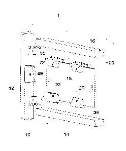
Il est décrit un système de soutien pour clôture de verre visant à soutenir une vaste gamme de panneaux de verre et doté dun grand nombre de blocs de serrage espacés. Chaque bloc définit un passage visant à recevoir lextrémité du panneau de verre et fixe les panneaux de verre aux blocs de serrage, au moyen de fixations dans les blocs pour le passage de ces dernières et dun grand nombre de trous de positionnement pour fixer les blocs de serrage à un substrat.


Abrégé anglais

A glass fence support system for supporting a plurality of glass panels and having a plurality of spaced apart clamp blocks, each defining a channel to receive the edge of the glass panel, and through fastenings in the blocks for passing fastening through openings in the glass panels to secure them in the channels, and a plurality of positioning holes for securing the clamp blocks to a substrate.

Revendications

Note : Les revendications sont présentées dans la langue officielle dans laquelle elles ont été soumises.


CLAIMS
We claim:
1. A glass fence support system for a glass fence having a series of spaced
apart fence posts
and a plurality of glass panels and comprising:
a plurality of clamp blocks, each defining a channel to receive an edge of a
glass panel;
a through fastening opening in each said clamp block registering with an
opening in the
glass panel to secure it;
a plurality of positioning holes in the clamp block for fasteners securing the
clamp block
to a substrate;
channel walls forming said channel; and
semi-circular groove formations formed in said channel walls on opposite sides
of each
channel permitting fastenings to be inserted therethrough, into said
substrate.
2. The glass fence support system as claimed in claim 1 wherein said clamp
blocks comprise
at least two parts.
3. The glass fence support system as claimed in claim 2 wherein said clamp
blocks comprise a
first block portion having abase defining a plane, and said positioning holes
extending
through said base for fastening said base to a substrate, and a fixed channel
wall portion
defining a plane normal to said base plane, and a movable channel wall portion
attachable
to said base.
4. The glass fence support system as claimed in claim 3 wherein said base
defines a base
attachment portion and wherein said movable channel wall portion defines a
moveable wall
attachment portion and wherein said base attachment portion and said moveable
wall
attachment portion are interengageable with one another to form a said clamp
block.
5. The glass fence support system as claimed in claim 4 wherein said base
attachment portion
comprises a base recess formed in said base, and wherein said moveable wall
attachment
portion defines a moveable wall protrusion interengageable with said base
recess.
Date Recue/Date Received 2022-12-16

6. The glass fence support system as claimed in claim 5 wherein said base
recess is an axial
groove formed in said base, and defining a base key way with undercut wall
regions, and
wherein said moveable wall protrusion defines an axial key bar, said key bar
having a cross
30 sectional shape complimentary to and interfitting with said base key
way.
7. The glass fence support system as claimed in claim 1, including a plurality
of vertical fence
posts, with clamp blocks secured in spaced apart locations on said posts for
securing
upright edges of said glass panels.
8. The glass fence support system as claimed in claim 1 including upper and
lower fence rails
with upper and lower clamp blocks secured to the upper and lower rails,
securing upper and
lower edges of the glass panels between them.
9. The glass fence support system as claimed in claim 1 including spacer pads
to
accommodate variations in spacings of upright post members in a fence system.
10. The glass fence support system as claimed in claim 9 including an
intermediate clamp block
40 in which the channel is open at both ends, for securing an intermediate
position on the glass
panel, and further including an end clamp block having a blind end formed at
one end of the
channel for securing the opposite ends of the glass panel at its corners.
11. The glass fence support system as claimed in claim 10 wherein the clamp
blocks are formed
of a synthetic material and including a metal reinforcement within said
synthetic material.
12. A glass fence comprising:
a plurality of upright fence posts mounted parallel to one another at spaced
apart
intervals;
a plurality of fence rails connected transversely between adjacent fence
posts;
a plurality of glass panels supported between adjacent said posts and said
fence rails;
50 clamp blocks secured to some of said fence posts and said fence
rails, and engaging
edge portions of respective glass panels;
a channel in each said clamp block to receive the edge of a glass panel;
11
Date Recue/Date Received 2022-12-16

through fastenings in each said clamp block registering with an opening in the
glass
panel to secure it in the channel;
a plurality of positioning holes for fasteners securing the clamp block to a
substrate;
channel walls forming said channels; and
semi-circular groove formations formed in said channel walls on opposite sides
of each
channel permitting fastenings to be inserted there through, into said
substrate.
13. The glass fence as claimed in claim 12 wherein said clamp blocks comprise
a base block
60 portion having a base defining a plane, and fastening holes in said
base for fastening said
base to a substrate, and a fixed wall portion defining a plane normal to said
base plane, and
further comprises a movable wall portion attachable to said base block
portion.
14. The glass fence as claimed in claim 13 wherein said base block portion
defines a base
attachment portion and wherein said movable wall defines a moveable wall
attachment
portion and wherein said respective attachment portions are interengageable
with one
another to form a said clamp block.
15. The glass fence as claimed in claim 14 wherein said base attachment
portion comprises a
base recess formed in said base, and wherein said moveable wall attachment
portion
defines a protrusion interengageable with said base recess.
70 16. The glass fence as claimed in claim 15 wherein said base recess is
an axial groove formed
in said base, and defining a key way with undercut wall regions, and wherein
said moveable
wall protrusion defines an axial key bar having a cross sectional shape
complimentary to
and interfitting with said key way.
17. The glass fence as claimed in claim 12 including an intermediate channel
block in which the
channel is open at both ends, for securing an intermediate position on the
glass panel, and
further including an end clamp block having a blind end formed at one end of
the channel for
securing the opposite ends of the glass panel at its corners.
12
Date Recue/Date Received 2022-12-16

Description

Note : Les descriptions sont présentées dans la langue officielle dans laquelle elles ont été soumises.


CA 02936011 2016-07-13
GLASS FENCE SUPPORT SYSTEM
FIELD OF THE INVENTION
The invention relates to a fences incorporating glass panels and in particular
to a fence
support system in which the glass panels are supported in a series of clamp
blocks
with channels for receiving the edges of the glass panels.
BACKGROUND OF THE INVENTION
Fence systems are usually made of either wood or metal. They are an
obstruction to
views of the surrounding terrain or the building, and they also require
periodic
maintenance.
Fence systems incorporating glass panels are becoming increasingly popular,
because
glass is virtually maintenance free, and also because glass permits visual
enjoyment of
the surroundings and is less intrusive.
In order to provide sufficient strength, it has been the practice to use glass
panels of
considerable thickness. Glass of this type is expensive. The clamps for
holding the
edges of the glass panels can also represent a heavy expense. Many such clamps
have several components, formed of cast metal, which must be assembled on
site. All
of this means that glass panel fences in the past, have been a relatively
expensive
solution to a problem. Another factor is that the glass panels will require
holes to be
formed at spaced intervals along the edges of the panels. The holes will
receive
fastening pins or bolts of various kinds. Forming such holes at precise
locations in glass
panels represents a considerable further expense. One solution has been to
provide
glass panel fences in which the glass panels were supported top or bottom in a
metal
rail system. The metal rail system was specially extruded and formed with
continuous
1
Th
Date recue/Date received 2023-04-05

CA 02936011 2016-07-13
channels, so that the edges of the glass panels along the bottom and top edge
of the
panel could be held within such channels and secured. This of course in turn
requires
specially formed metal fence posts and metal railings with channels
dimensioned and
designed specifically to receive the glass panels of a predetermined
thickness.
Clearly it is desirable to make a glass fence system which is more adaptable
to a
variety of different locations, and having clamps which are adaptable to a
variety of
different types of fence posts and supporting rails. In this way, it also
lends itself to the
use of glass panels of somewhat reduced thickness. The net result of all these
modifications can be a considerable reduction in costs.
BRIEF SUMMARY OF THE INVENTION
With a view to overcoming these various disadvantages, the invention provides
a glass
fence support system for a fence having a plurality of glass panels, and
having a
plurality of spaced apart clamp blocks, each defining a channel to receive the
edge of
the glass panel, and through fastenings in said clamp blocks passing through
openings in the glass panel to secure it in the channel, and a plurality of
positioning
holes for securing the clamp to a substrate.
Preferably the fence support system will incorporate a plurality of vertical
fence posts.
The clamp blocks may be secured in spaced apart locations on said posts for
securing
upright edges of said glass panels.
Optionally there may be both upper and lower rails with upper and lower clamp
blocks
secured to the upper and lower rails, securing upper and lower edges of the
glass
panels between them.
2

CA 02936011 2016-07-13
Preferably the fastenings for securing the clamp blocks to the substrate will
pass
through holes formed in the bottom of the channel with semi circular groove
formations
formed in opposite sides of the channel permitting fastenings to be secured
there
through.
In a further embodiment, spacer pads may be employed to accommodate slight
variations in spacings of upright post members in a fence system, positioning
the clamp
blocks in the correct location for securing the edges of the glass panels.
Preferably there will be at least two types of clamp blocks, one being an
intermediate
clamp block in which the channel is open at both ends, for securing an
intermediate
position of the glass panel, and the other of said clamp blocks being an end
clamp
block having a blind end formed at one end of the channel for securing the
opposite
ends of the glass panel at its corners.
In one embodiment, the clamp blocks may be formed of a synthetic material, and
may
incorporate a metal reinforcement within the material.
In a particularly preferred embodiment, the clamp blocks may be made in two
portions,
to facilitate the positioning of the glass relative to the clamp blocks.
The various features of novelty which characterize the invention are pointed
out
with more particularity in the claims annexed to and forming a part of this
disclosure.
For a better understanding of the invention, its operating advantages and
specific
objects attained by its use, reference should be made to the accompanying
drawings
and descriptive matter in which there are illustrated and described preferred
embodiments of the invention.
3

CA 02936011 2016-07-13
IN ME DRAWINGS
Figure us an exploded schematic perspective illustration showing part of a
typical
fence system, illustrating the invention, partially exploded;
Figure 2 is a side elevation showing an intermediate clamp block and an end
clamp
block, and a glass panel;
Figure 3 is a section along 3-3 of Fig2;
Figure 4 is a top plan of Fig 2;
Figure 5 is a perspective illustration of an end clamp block;
Figure 6 is a top plan of the clamp block of Fig 5;
Figure 7 is a section along 7-7;
Figure 8 is a section along 8-8;
Figure 9 is a perspective of an intermediate clamp block;
Figure 10a, 10B illustrate various alternate shapes;
Figure lla is a perspective of a spacer shim;
Figure 11 b is a plan view of the underside of a clamp block;
Figure 12 is a perspective of a further embodiment; and,
Figure 13 is a top plan of Figure 12.
4

CA 02936011 2016-07-13
DESCRIPTION OF A SPECIFIC EMBODIMENT
Referring first of all to Figure 1, it will be seen that this illustrates one
embodiment of the
invention. The illustration shows a typical fence indicated generally as (10).
Such a typical fence will consist of a series of upright fence posts (12)
mounted on
bases (not shown) on a substrate or alternatively simply embedded in concrete
bases
such as is well known in the art. The fence posts may be of wood, and may also
be
typically of metal. Fence rails (14) and (16) extend between posts (12).
Between the fence posts, panels of glass, rectangular in this case and
indicated
generally as (18) are supported. The glass panels are supported by means of
intermediate clamp blocks (20) and end clamp blocks (22). The clamp blocks may
be
secured to the posts at spaced apart intervals as shown. The lower horizontal
edge of
the glass panels may be supported on a fence rail by clamp blocks (20 or 22).
Similarly, if required the upper horizontal edge of the glass panels may be
supported by
an upper fence rail, and attached thereto by means of clamp blocks (20 or 22).
Depending on the dimensions of the glass panels, there may be varying numbers
of
clamp blocks. End clamp blocks (22) are located at the end corners of the
glass
panels. In this way, the respective adjacent corners of the glass panels are
held in the
end clamp blocks (22) and intermediate the two end corners, the glass panels
are
supported by intermediate clamp blocks (20).
The clamp blocks are illustrated in greater detail in Figures 2,3,4 and 5.
Each end
clamp block (22) in this embodiment, may comprise a single homogenous integral
molded body, typically formed of synthetic plastic material, although
optionally being
5

CA 02936011 2016-07-13
formed of cast metal if desired.
Each end clamp block (22 ) will define a base portion (24), and two upstanding
flange
wall portions (26). Between the two upstanding flange wall portions, an axial
channel
(28) is provided dimensioned to receive the edge of the glass panel. In the
case of the
end clamp blocks, one end of the channel is closed off as at (30), the
opposite end of
the channel being open.
In order to secure the clamp block to a fence post or rail, a plurality of
fastening holes
(32) are formed perpendicularly through the base (24). Access to the fastening
holes
will be provided through the channel (28). For this purpose the channel (28)
is formed
with generally semi-arcuate grooves (34), in the flanges (26) defining the
channel, the
grooves being axially aligned with the holes. In this way a typical fastening
such as a
screw or bolt (36) can be passed down through the channel (28) with its head
sliding
within the two grooves (34) and the threaded portion of the fastening passing
through
the fastening hole.
In the case of the end clamp block, there are three such fastening holes and a
total of
six grooves, in this embodiment.
The intermediate clamp blocks (20) are shown in Figure 9. The intermediate
clamp
blocks have two upstanding flange wall portions (38) defining an axial channel
(40).
The channel (40) is open at both ends so that the intermediate clamp block can
be
secured to the edge of the glass panel intermediate its corners.
Fastening holes (42) are provided perpendicularly through base (44). Access is
given
to those fastening holes by means of grooves (48) formed in the opposite sides
of the
flanges (38) defining the channel.
6
--"t+

CA 02936011 2016-07-13
In the case of the illustrated clamp blocks, the base is formed with generally
sloping
wedge shaped side surfaces (50), and the flanges are formed as upstanding
portions,
merging with the angled side surfaces (50).
The clamp blocks could be formed with a generally concave or even convex
arcuate
exterior or any other exterior shaping which is considered desirable.
The end and intermediate clamp blocks in this embodiment are formed as one
piece
homogenous integrally molded structures, which may be molded of synthetic
plastic
material or which may be of cast metal
In some areas it may be required that the clamp blocks be reinforced in some
way. In
this case, a modified clamp block (52) as shown in Figure 10 may be provided.
In this
case, while the clamp block (52) is formed of integrally molded one piece
synthetic
plastic, a metal reinforcement (54 ) can be incorporated, as shown. The
reinforcement
(54) is generally a U-shaped piece of rigid metal which is embedded within the
synthetic plastic when it is molded.
In some cases, it may be that there is difficulty in achieving the precise
spacing
between the fence posts. Spacing between the fence posts should correspond to
the
width of the glass panels, allowing for sufficient spacing for the attachment
of the clamp
blocks. In some cases, however it may be necessary to incorporate spacer pads,
or
"shims" , indicated generally as (56) Fig 11 a.
These shims (56) would be rectangular blocks of material of any suitable type
which
can be placed between the base of the clamp block and the fence post.
The shims (56 ) would be provided with suitable fastening openings (58) for
receiving
the fastening from the clamp blocks, and allowing the fastenings to be
inserted in the
7

CA 02936011 2016-07-13
fence post.
Shims (56) are additionally provided with locating pins (60), dimensioned and
positioned to receive locating recesses (62) on the under side of each clamp
block
(Fig 11a and 11 b).
In order to secure the glass, each clamp block has transverse through openings
(70),
with interior threads, formed in the flanges. Threaded bolts (72) are passed
through the
openings (70).
The glass panels are provided with notches (74) to accept the bolts (72).
While the foregoing clamp blocks are capable of and suitable for performing
the
purpose intended, in some cases it may be desirable to make the clamp blocks
with
one side removable. Such an embodiment is shown in Figures 12 and 13. It will
be
seen that in this case, a modified form of clamp block (80) is shown. This
clamp block
(80) has a base (82 ) and an integral upstanding channel flange wall (84).
Fastening
holes (86) are provided for securing the base to a substrate or a post. In
this case, an
optional centre fastening hole (88) is shown having a recess of hexagonal
outline. This
is suitable where it is desirable to secure the clamp blocks by means of bolts
(not
shown) typically having a hex head.
Along one side of the base (82), there is an axial groove (90). The groove
(90) has a
shape typically in the form of a key way, with diagonal undercuts (92).
The clamp block (80) further comprises a movable channel flange wall (94),
having
complimentary grooves (96) and hex recess (98), for permitting access of
fastenings as
before. Transverse threaded openings (100) are provided to receive a locking
bolt as
before.
8
Th
-Thµ

CA 02936011 2016-07-13
However in this case, the removable wall (94) is provided with an axial key
bar
(102). The key bar (102) is shaped to conform to the interior shape of the key
way
groove (90). Assembly proceeds by securing the base (82) to a post or rail and
then
positioning the glass panel against the fixed wall (84). The key bar (102) of
the
removable wall (94) is then slid into position in groove (90), and the locking
bolt is
inserted through recesses (100) in the side walls and the hioles in the glass
panel, thus
holding both the fixed side wall and the removable side wall together.
This arrangement will speed up and facilitate the erection of glass panels in
many
cases.
While Figures 12 and 13 illustrate and describe this modification in use on an
intermediate clamp block, it will be appreciated that the same modifications
will be
applied to the end or corner clamp blocks as well, with minor modifications.
The foregoing is a description of a preferred embodiment of the invention
which
is given here by way of example only. The invention is not to be taken as
limited to any
of the specific features as described, but comprehends all such variations
thereof as
come within the scope of the appended claims.
9

Dessin représentatif
Une figure unique qui représente un dessin illustrant l'invention.
États administratifs

2024-08-01 : Dans le cadre de la transition vers les Brevets de nouvelle génération (BNG), la base de données sur les brevets canadiens (BDBC) contient désormais un Historique d'événement plus détaillé, qui reproduit le Journal des événements de notre nouvelle solution interne.

Veuillez noter que les événements débutant par « Inactive : » se réfèrent à des événements qui ne sont plus utilisés dans notre nouvelle solution interne.

Pour une meilleure compréhension de l'état de la demande ou brevet qui figure sur cette page, la rubrique Mise en garde , et les descriptions de Brevet , Historique d'événement , Taxes périodiques et Historique des paiements devraient être consultées.

Historique d'événement

Description Date
Inactive : Octroit téléchargé 2023-08-02
Accordé par délivrance 2023-08-01
Lettre envoyée 2023-08-01
Inactive : Page couverture publiée 2023-07-31
Préoctroi 2023-05-24
Inactive : Taxe finale reçue 2023-05-24
Lettre envoyée 2023-05-12
Un avis d'acceptation est envoyé 2023-05-12
Inactive : Approuvée aux fins d'acceptation (AFA) 2023-05-10
Inactive : Q2 réussi 2023-05-10
Modification reçue - modification volontaire 2023-04-05
Entrevue menée par l'examinateur 2023-04-05
Retirer de l'acceptation 2023-04-03
Inactive : Demande ad hoc documentée 2023-02-26
Inactive : Approuvée aux fins d'acceptation (AFA) 2023-02-23
Inactive : Q2 réussi 2023-02-23
Modification reçue - modification volontaire 2022-12-16
Modification reçue - réponse à une demande de l'examinateur 2022-12-16
Rapport d'examen 2022-12-14
Inactive : Q2 échoué 2022-12-06
Modification reçue - modification volontaire 2022-10-07
Modification reçue - modification volontaire 2022-10-04
Modification reçue - réponse à une demande de l'examinateur 2022-10-04
Rapport d'examen 2022-09-15
Inactive : Rapport - Aucun CQ 2022-08-24
Lettre envoyée 2021-06-22
Requête pour le changement d'adresse ou de mode de correspondance reçue 2021-06-14
Requête d'examen reçue 2021-06-14
Exigences pour une requête d'examen - jugée conforme 2021-06-14
Toutes les exigences pour l'examen - jugée conforme 2021-06-14
Inactive : COVID 19 - Délai prolongé 2020-07-02
Représentant commun nommé 2019-10-30
Exigences relatives à la révocation de la nomination d'un agent - jugée conforme 2019-06-18
Exigences relatives à la nomination d'un agent - jugée conforme 2019-06-18
Demande visant la révocation de la nomination d'un agent 2019-05-13
Demande visant la nomination d'un agent 2019-05-13
Inactive : Lettre officielle 2019-05-03
Demande visant la révocation de la nomination d'un agent 2019-01-22
Demande visant la nomination d'un agent 2019-01-22
Demande de prorogation de délai pour compléter le paiement de la taxe applicable aux petites entités reçue 2017-06-20
Demande de prorogation de délai pour compléter le paiement de la taxe applicable aux petites entités reçue 2017-06-19
Demande publiée (accessible au public) 2017-01-20
Inactive : Page couverture publiée 2017-01-20
Inactive : CIB en 1re position 2016-08-29
Inactive : CIB attribuée 2016-08-29
Exigences de dépôt - jugé conforme 2016-07-20
Inactive : Certificat dépôt - Aucune RE (bilingue) 2016-07-20
Demande reçue - nationale ordinaire 2016-07-15
Déclaration du statut de petite entité jugée conforme 2016-07-13

Historique d'abandonnement

Il n'y a pas d'historique d'abandonnement

Taxes périodiques

Le dernier paiement a été reçu le 2023-05-24

Avis : Si le paiement en totalité n'a pas été reçu au plus tard à la date indiquée, une taxe supplémentaire peut être imposée, soit une des taxes suivantes :

  • taxe de rétablissement ;
  • taxe pour paiement en souffrance ; ou
  • taxe additionnelle pour le renversement d'une péremption réputée.

Veuillez vous référer à la page web des taxes sur les brevets de l'OPIC pour voir tous les montants actuels des taxes.

Historique des taxes

Type de taxes Anniversaire Échéance Date payée
Taxe pour le dépôt - petite 2016-07-13
TM (demande, 2e anniv.) - petite 02 2018-07-13 2018-07-04
TM (demande, 3e anniv.) - petite 03 2019-07-15 2019-07-03
TM (demande, 4e anniv.) - petite 04 2020-07-13 2020-07-07
Requête d'examen - petite 2021-07-13 2021-06-14
TM (demande, 5e anniv.) - petite 05 2021-07-13 2021-06-14
TM (demande, 6e anniv.) - petite 06 2022-07-13 2022-05-31
Taxe finale - petite 2023-05-24
TM (demande, 7e anniv.) - petite 07 2023-07-13 2023-05-24
TM (brevet, 8e anniv.) - petite 2024-07-15 2024-05-21
Titulaires au dossier

Les titulaires actuels et antérieures au dossier sont affichés en ordre alphabétique.

Titulaires actuels au dossier
MAURIZIO C. BERTATO
Titulaires antérieures au dossier
S.O.
Les propriétaires antérieurs qui ne figurent pas dans la liste des « Propriétaires au dossier » apparaîtront dans d'autres documents au dossier.
Documents

Pour visionner les fichiers sélectionnés, entrer le code reCAPTCHA :


Pour visualiser une image, cliquer sur un lien dans la colonne description du document. Pour télécharger l'image (les images), cliquer l'une ou plusieurs cases à cocher dans la première colonne et ensuite cliquer sur le bouton "Télécharger sélection en format PDF (archive Zip)" ou le bouton "Télécharger sélection (en un fichier PDF fusionné)".

Liste des documents de brevet publiés et non publiés sur la BDBC .

Si vous avez des difficultés à accéder au contenu, veuillez communiquer avec le Centre de services à la clientèle au 1-866-997-1936, ou envoyer un courriel au Centre de service à la clientèle de l'OPIC.


Description du
Document 
Date
(aaaa-mm-jj) 
Nombre de pages   Taille de l'image (Ko) 
Page couverture 2023-06-30 1 37
Dessin représentatif 2023-06-30 1 11
Description 2016-07-13 9 368
Abrégé 2016-07-13 1 13
Revendications 2016-07-13 4 171
Dessins 2016-07-13 5 111
Dessin représentatif 2016-12-23 1 9
Page couverture 2017-01-20 2 35
Revendications 2022-10-04 3 186
Revendications 2022-10-07 3 186
Revendications 2022-12-16 3 185
Description 2023-04-05 9 479
Paiement de taxe périodique 2024-05-21 1 26
Certificat de dépôt 2016-07-20 1 204
Rappel de taxe de maintien due 2018-03-14 1 111
Avis de rappel: Taxes de maintien 2019-04-16 1 130
Courtoisie - Réception de la requête d'examen 2021-06-22 1 434
Avis du commissaire - Demande jugée acceptable 2023-05-12 1 579
Taxe finale 2023-05-24 5 174
Taxe finale 2023-05-24 5 127
Certificat électronique d'octroi 2023-08-01 1 2 527
Nouvelle demande 2016-07-13 2 75
Mécanisme de redressement 2017-06-19 1 20
Mécanisme de redressement 2017-06-20 1 22
Courtoisie - Lettre du bureau 2019-05-03 1 34
Paiement de taxe périodique 2019-07-03 1 26
Paiement de taxe périodique 2020-07-07 1 26
Paiement de taxe périodique 2021-06-14 1 26
Requête d'examen 2021-06-14 5 182
Changement à la méthode de correspondance 2021-06-14 4 111
Paiement de taxe périodique 2022-05-31 1 26
Demande de l'examinateur 2022-09-15 4 228
Modification / réponse à un rapport 2022-10-04 6 255
Modification / réponse à un rapport 2022-10-07 6 248
Demande de l'examinateur 2022-12-14 3 130
Modification / réponse à un rapport 2022-12-16 6 255
Note relative à une entrevue 2023-04-05 1 20
Modification / réponse à un rapport 2023-04-05 5 182
Paiement de taxe périodique 2023-05-24 1 26