Note : Les descriptions sont présentées dans la langue officielle dans laquelle elles ont été soumises.
CA 02936022 2016-07-05
WO 2015/117075 PCT/US2015/014091
Coupling of Permanent Magnets in Electric Motors
Cross-Reference to Related Applications
[0001] This application is a non-provisional application which claims priority
from U.S.
provisional application number 61/935,185, filed February 3, 2014.
Technical Field/Field of the Disclosure
[0002] The present disclosure relates generally to permanent magnet electric
motors, and
specifically to the bonding of permanent magnets to a rotor or stator of a
permanent magnet
electric motor.
Background of the Disclosure
[0003] In general, electric motors operate by rotating a rotor relative to a
fixed stator by varying
the orientation of a magnetic field induced by one or more coils. In some
electric motors, both
the rotor and stator include coils. In such an induction motor, the magnetic
field induced by the
stator coils induces current within the rotor coils which, due to Lenz's law,
causes a resultant
torque on the rotor, thus causing rotation.
[0004] In a permanent magnet motor, on the other hand, the rotor includes one
or more
permanent magnets. The permanent magnets, in attempting to align with the
magnetic field
induced by the coils in the stator, cause a resultant torque on the rotor. By
varying the orientation
of the magnetic field, the rotor may thus be caused to rotate. In high-torque
permanent magnet
motors, multiple permanent magnets may be positioned on the exterior of the
rotor (for an
internal rotor permanent magnet motor).
[0005] While in operation, the components of the permanent magnet motor may
heat up in
response to, for example, electrical resistance in the stator coils, losses in
iron core of stator,
1
CA 02936022 2016-07-05
WO 2015/117075 PCT/US2015/014091
induced currents in rotor caused by harmonics, mechanical friction, etc.
Because of this increase
in heat, the permanent magnets must be bonded to the rotor in such a way that
any thermal
expansion of the rotor or permanent magnets will not cause the permanent
magnets to fracture or
separate from the rotor. Additionally, in cases where the permanent magnets
are formed by, for
example, sintering, the permanent magnets themselves may be relatively
brittle. Furthermore,
where the permanent magnets are constructed of a material with a different
thermal expansion
coefficient than the rotor, as is often the case, the thermal expansion of the
rotor may cause the
permanent magnets to crack.
Summary
[0006] The present disclosure provides for a method for coupling permanent
magnets to a rotor.
The method may include providing a rotor body, the rotor body being generally
cylindrical in
shape, the rotor body having an outer surface; forming a mounting hole in the
rotor body, the
mounting hole positioned to couple to a threaded connector; providing a
permanent magnet, the
permanent magnet being generally in the form of an annular section, the
concave surface of the
permanent magnet having a diameter generally equal to the outer diameter of
the rotor body, the
permanent magnet having a hole formed therein positioned to receive the
threaded connector, the
hole having a countersink formed therein at the convex surface of the
permanent magnet;
positioning the permanent magnet on the outer surface of the rotor body so
that the hole of the
permanent magnet is in alignment with the mounting hole; positioning an
elastomeric body
within the countersink; positioning the threaded connector through the
elastomeric body and the
hole of the permanent magnet; coupling the threaded connector to the rotor
body.
[0007] The present disclosure also provides for a rotor for a permanent magnet
electric motor.
The rotor may include a rotor body, the rotor body being generally cylindrical
in shape and
2
CA 02936022 2016-07-05
WO 2015/117075 PCT/US2015/014091
having an outer surface. The rotor body may include a mounting hole positioned
to couple to a
threaded connector. The rotor may also include a permanent magnet. The
permanent magnet may
be generally in the form of an annular section. The concave surface of the
permanent magnet
may have a diameter generally equal to the outer diameter of the rotor body.
The permanent
magnet may have a hole formed therein positioned to receive the threaded
connector. The hole
may have a countersink formed therein at the convex surface of the permanent
magnet. The rotor
may also include an elastomeric body positioned within the countersink between
the threaded
connector and the permanent magnet.
[0008] The present disclosure also provides for a method. The method may
include providing a
rotor body. The rotor body may be generally cylindrical in shape. The rotor
body may have an
outer surface. The outer surface of the rotor body may have at least one
dovetail channel. The
method may also include providing a permanent magnet. The permanent magnet may
be
generally in the form of an annular section. The concave surface of the
permanent magnet may
have a diameter generally equal to the outer diameter of the rotor body. The
permanent magnet
may include at least one dovetail adapted to fit into the dovetail channel.
The method may
further include sliding the permanent magnet on the outer surface of the rotor
body so that the
dovetail couples to the dovetail channel.
[0009] The present disclosure also provides for a method. The method may
include providing a
rotor body. The rotor body may be generally cylindrical in shape. The rotor
body may have an
outer surface. The method may further include providing a retaining ring. The
method may
further include providing a permanent magnet. The permanent magnet may
generally be in the
form of an annular section. The concave surface of the permanent magnet may
have a diameter
generally equal to the outer diameter of the rotor body. The permanent magnet
may have at least
3
CA 02936022 2016-07-05
WO 2015/117075 PCT/US2015/014091
one flange extending from an end of the permanent magnet. The flange may be
adapted to allow
the retaining ring to hold the permanent magnet to the rotor body by
compressing the flange to
the rotor body. The method may further include positioning the permanent
magnet on the outer
surface of the rotor body. The method may further include positioning the
retaining ring about
the rotor body and permanent magnet such that the retaining ring is generally
aligned with the
flange.
Brief Description of the Drawings
[0010] The present disclosure is best understood from the following detailed
description when
read with the accompanying figures. It is emphasized that, in accordance with
the standard
practice in the industry, various features are not drawn to scale. In fact,
the dimensions of the
various features may be arbitrarily increased or reduced for clarity of
discussion.
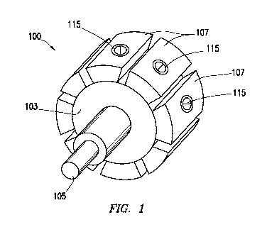
[0011] FIG. 1 depicts a rotor having permanent magnets affixed thereto
consistent with
embodiments of the present disclosure.
[0012] FIG. 2 depicts a partial cross section of the rotor of FIG. 1.
[0013] FIG. 3 depicts a partial cross section of a rotor having permanent
magnets affixed thereto
consistent with embodiments of the present disclosure.
[0014] FIGS. 4a, 4b depict a rotor having permanent magnets affixed thereto
consistent with
embodiments of the present disclosure.
Detailed Description
[0015] It is to be understood that the following disclosure provides many
different embodiments,
or examples, for implementing different features of various embodiments.
Specific examples of
4
CA 02936022 2016-07-05
WO 2015/117075 PCT/US2015/014091
components and arrangements are described below to simplify the present
disclosure. These are,
of course, merely examples and are not intended to be limiting. In addition,
the present
disclosure may repeat reference numerals and/or letters in the various
examples. This repetition
is for the purpose of simplicity and clarity and does not in itself dictate a
relationship between
the various embodiments and/or configurations discussed.
[0016] As depicted in FIG. 1, rotor 101 for use in a permanent magnet motor
may include rotor
body 103. Rotor body 103 may be generally cylindrical in shape. In some
embodiments, rotor
body 103 may be coupled to output shaft 105. As rotor 101 is rotated within
the permanent
magnet motor, output shaft 105 serves to transfer the rotational power
generated by rotor 101 to
other equipment (not shown).
[0017] Rotor 101 may, in some embodiments, include one or more permanent
magnets 107
positioned about the exterior surface of rotor body 103. In some embodiments,
as depicted in
FIG. 1, permanent magnets 107 may be annular in shape. The concave surface of
each permanent
magnet 107 may have generally the same diameter as the exterior surface of
rotor body 103.
Permanent magnets 107 may be configured such that the magnetic axis of each
permanent
magnet is substantially aligned to be normal to the surface of rotor body 103.
In some
embodiments, the magnetic field of adjacent permanent magnets 107 are in
opposition, so that
the magnetic pole of permanent magnets 107 alternate between North and South.
In some
embodiments, permanent magnets 107 may be formed by sintering of permanent
magnet
material such as, for example and without limitation, a rare-earth magnet such
as neodymium. In
other embodiments, permanent magnets 107 may be formed by a rapid
solidification process as
understood in the art.
CA 02936022 2016-07-05
WO 2015/117075 PCT/US2015/014091
[0018] As depicted in FIG. 2, permanent magnet 107 may be coupled to rotor
body 103. In some
embodiments, permanent magnet 107 may have one or more holes 109 formed
therein. Hole 109
is aligned so that when permanent magnet 107 is placed on the outer surface of
rotor body 103,
hole 109 extends in a direction normal to the surface of rotor body 103. In
some embodiments,
hole 109 may include countersink 111. Rotor body 103 may include one or more
mounting holes
113 positioned to align with holes 109 of permanent magnets 107. In some
embodiments,
mounting holes 113 may be tapped to accept the thread of threaded fastener
115. In some
embodiments, threaded fastener 115 may be, for example and without limitation,
a screw, bolt,
or other threaded fastener. Countersink 111 may allow threaded fastener 115
to, when installed,
remain below the outer surface of permanent magnet 107 which may, for example,
avoid
interference between threaded fastener 115 and other parts of the permanent
magnet motor.
[0019] In some embodiments, a thread-locking compound may be applied to
threaded fastener
115 to, for example, prevent threaded fastener 115 from unintentionally
unthreading from rotor
body 103. In some embodiments, a potting material or adhesive may be applied
between, for
example, rotor body 103 and permanent magnet 107.
[0020] In the embodiment depicted in FIG. 2, threaded fastener 115 is a
flathead screw with a
matching tapered profile to that of countersink 111. One having ordinary skill
in the art with the
benefit of this disclosure will understand that threaded fastener 115 may be
replaced by a
threaded connector having a different profile without deviating from the scope
of this disclosure.
Likewise, countersink 111 may have a different profile such as, for example
and without
limitation, a counterbore without deviating from the scope of this disclosure.
For the purposes of
this disclosure, the term "countersink" is intended to include both
countersinks and counterbores
unless specifically differentiated.
6
CA 02936022 2016-07-05
WO 2015/117075 PCT/US2015/014091
[0021] In some embodiments, elastomeric body 117 may be positioned between the
head of
threaded fastener 115 and permanent magnet 107 when permanent magnet 107 is
installed to
rotor body 103. Elastomeric body 117 may be formed of an elastomeric material,
allowing
elastomeric body 117 to be installed under elastic compression between
threaded fastener 115
and permanent magnet 107. Because threaded fastener 115 may have a thermal
expansion
coefficient and/or thermal conductivity different from that of permanent
magnet 107, threaded
fastener 115 may thermally expand and increase in length more rapidly than
permanent magnet
107 as permanent magnet 107, threaded fastener 115, and rotor body 103
increase in temperature
during normal use. In such a case, the compressive stress on elastomeric body
117 between
threaded fastener 115 and permanent magnet 107 may decrease. Elastomeric body
117, being
elastically deformed, increases in size as the stress thereon decreases, which
may maintain the
compressive force between threaded fastener 115 and permanent magnet 107.
Elastomeric body
117 may thus, for example, prevent any loosening of the attachment between
permanent magnet
107 and rotor body 103.
[0022] Although depicted as a single 0-ring, elastomeric body 117 may, in some
embodiments,
be, for example and without limitation, a single 0-ring, multiple 0-rings, an
elastomeric washer,
or a combination thereof
[0023] Likewise, as threaded fastener 115 and permanent magnet 107 decrease in
temperature
during normal operation of the permanent magnet motor, for example when the
permanent
magnet motor is shut off, threaded fastener 115 may thermally contract more
rapidly than
permanent magnet 107. In this case, the compressive stress on elastomeric body
117 between
threaded fastener 115 and permanent magnet 107 may increase. Elastomeric body
117 may
elastically deform to, for example, prevent excess force from being exerted on
permanent magnet
7
CA 02936022 2016-07-05
WO 2015/117075 PCT/US2015/014091
107 by threaded fastener 115. Elastomeric body 117 may thus, for example,
prevent threaded
fastener 115 from crushing permanent magnet 107.
[0024] In order to assemble rotor 101, a rotor body 103 may be provided. One
or more mounting
holes 113 may be formed in the exterior surface of rotor body 103. In some
embodiments,
mounting holes 113 may be tapped to receive a threaded fastener. One or more
permanent
magnets 107, having at least one hole 109 formed therein, each hole 109
positioned to align with
a corresponding mounting hole 113, each hole 109 having countersink 111, is
then positioned
onto the outer surface of rotor body 103. Elastomeric body 117 is then placed
within countersink
111. A threaded fastener, such as threaded fastener 115, is then threaded into
hole 109 and
mounting hole 113, such that the head of threaded fastener 115 mechanically
couples permanent
magnet 107 to rotor body 103.
[0025] Although FIG. 1 depicts a permanent magnet 107 being coupled to rotor
body 103 by
only one threaded fastener 115, one having ordinary skill in the art with the
benefit of this
disclosure will understand that multiple screws 115 may be utilized for each
permanent magnet
107. Additionally, although depicted as being used for an internal rotor
permanent magnet motor,
one having ordinary skill in the art with the benefit of this disclosure will
understand that
permanent magnets 107 may be installed to the interior surface of a tubular
rotor of an external
rotor permanent magnet motor without deviating from the scope of this
disclosure. Likewise,
although described with permanent magnets 107 coupled to the rotor of a
permanent magnet
motor, permanent magnets 107 may be coupled to the stator of a permanent
magnet motor in
which the coils are positioned on the rotor without deviating from the scope
of this disclosure.
8
CA 02936022 2016-07-05
WO 2015/117075 PCT/US2015/014091
[0026] In some embodiments, rotor 201 may include rotor body 203 as depicted
in FIG. 3. Rotor
body 203 may include one or more dovetail channels 205 adapted to interface
with permanent
magnets 207. In such embodiments, permanent magnets 207 may include magnet
dovetail 209
adapted to fit into dovetails 205 and thus retain permanent magnet 207 to
rotor body 203. In such
an embodiment, permanent magnet 207 may be slid into dovetail channels 205
during assembly.
In some embodiments, dovetail channels 205 may be formed by removing material
from rotor
body 203. In some embodiments, dovetail channels 205 may be formed as a
separate piece from
rotor body 203 and affixed thereto by, for example and without limitation,
threaded couplers. In
some embodiments, dovetail channels 205 may be coupled to rotor body 203 by
threaded
couplers as described above.
[0027] In some embodiments, rotor 301 may include rotor body 303 as depicted
in FIGS. 4a, 4b.
Permanent magnets 305 may include one or more flanges 307 as depicted in FIG.
4a. Flanges
307 may, for example and without limitation, be adapted to receive retaining
ring 309 when
installed as depicted in FIG. 4b. Retaining ring 309 may be adapted to
encircle rotor body 303
and flanges 307 of permanent magnets 305 in order to retain permanent magnets
305 to rotor
body 303. In some embodiments, retaining ring 309 may be a split ring, the
ends of which being
coupled to one or more of rotor body 303 or the other end of retaining ring
309.
[0028] The foregoing outlines features of several embodiments so that a person
of ordinary skill
in the art may better understand the aspects of the present disclosure. Such
features may be
replaced by any one of numerous equivalent alternatives, only some of which
are disclosed
herein. One of ordinary skill in the art should appreciate that they may
readily use the present
disclosure as a basis for designing or modifying other processes and
structures for carrying out
the same purposes and/or achieving the same advantages of the embodiments
introduced herein.
9
CA 02936022 2016-07-05
WO 2015/117075 PCT/US2015/014091
One of ordinary skill in the art should also realize that such equivalent
constructions do not
depart from the spirit and scope of the present disclosure and that they may
make various
changes, substitutions, and alterations herein without departing from the
spirit and scope of the
present disclosure.