Note : Les descriptions sont présentées dans la langue officielle dans laquelle elles ont été soumises.
CA 02936778 2016-07-13
1
DESCRIPTION
DOOR LATCH.DEVICE FOR VEHICLE AND DOOR SYSTEM PROVIDED WITH
DOOR LATCH DEVICE
Field
[0001] The present invention relates to a door latch
device for vehicle, having a function for detecting a door-
opening operation, and to a door system provided with the
door latch device.
Background
[0002] Among a vehicle door system that includes a door
latch device for retaining a door in a closed state and
includes a window regulator for causing a glass window to
perform an opening and closing operation, there has been a
system that, based on a door-opening operation, performs
drive control of a driving source of a window regulator to
cause the glass window to perform an opening operation
automatically for a predetermined amount. This type of
system has intended to improve a sealing property of a
2C weather-strip on a sash-less door, or to prevent an
increase of a closing force of the door due to a raised
indoor pressure at the moment of closing of the door (refer
to Patent Literature 1, for example).
Citation List
Patent Literature
[0003] Patent Literature 1: Japanese Patent Application
Laid-open No. 2004-82808
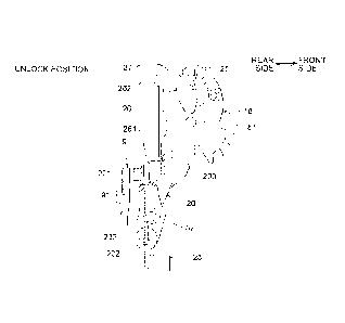
Summary
Technical Problem
[0004] The opening operation of the glass window to open
automatically for a predetermined amount based on the door-
opening operation, as described above, needs to be
executable only when following three conditions are
CA 02936778 2016-07-13
2
satisfied in view of anti-theft property, and practicality.
(1) the door is in a closed state (2) a locking/unlocking
mechanism of the door latch device is in an unlock state
and (3) door-opening operation is performed with an
operation handle on the door for door-opening (outside
handle or inside handle).
[0005] In order to allow the above-described operation
to be executable only when the three conditions are
satisfied, however, a lot of detection switches for
detecting a state of each of components are required. In
particular, since detecting an unlock position of the
locking/unlocking mechanism of the door latch device, and
detecting a door-opening operation, may need at least two
detection switches, problems arise in some cases that the
door latch device structure, or control of a control
circuit device for controlling an electric driving source
of the window regulator may become complicated.
[0006] In view of the above-described problems, the
present invention is intended to provide a door latch
device for vehicle capable of, using a detection switch,
detecting a door-opening operation of an operation handle
when a locking/unlocking mechanism is in an unlatch
position, and a door system provided with the door latch
device.
Solution to Problem
[0007] To solve the above-described problem, a first
invention includes: a meshing mechanism configured to be
meshable with a striker when a door is closed; a
locking/unlocking mechanism configured to be movable to an
unlock position where an opening operation of an operation
handle provided at the door is enabled and where meshing of
the meshing mechanism is releasable, and to be movable to a
lock position where the opening operation of the operation
CA 02936778 2016-07-13
3
handle provided at the door is disabled and where meshing
of the meshing mechanism is unreleasable; a smart lever
configured-to be operable in linking with the opening
operation of the operation handle when the
locking/unlocking mechanism is in the unlock position, and
to be inoperable in linking with the opening operation of
the operation handle when the locking/unlocking mechanism
is in the lock position; and a smart lever detection switch
configured to be detectable an operation of the smart
lever.
[0008] In the first invention, according to a second
invention, the smart lever operates by abutting the
locking/unlocking mechanism that operates in linking with
the opening operation of the operation handle when the
locking/unlocking mechanism is in the unlock position.
[0009] A third invention includes: the door latch device
for vehicle according to the first invention or the second
invention; a door open/close detection switch configured to
be detectable closing of a door; a window regulator
configured to be capable of opening and closing a glass
window provided at the door using power of an electric
driving source; and a control circuit device configured to
control drive of the electric driving source. The control
circuit device performs opening drive control of the
electric driving source for a predetermined time, triggered
by detection of operation of the smart lever by the smart
lever detection switch when the door open/close detection
switch is detecting the closing of the door, and performs
closing drive control of the electric driving source
triggered by detection of closing of the door by the door
open/close detection switch.
Advantageous Effects of Invention
CA 02936778 2016-07-13
4
[0010] According to the present invention, there are
provided a smart lever and a smart lever detection switch.
The smart lever is operable in linking with an opening
operation of the operation handle when the
locking/unlocking mechanism is in an unlock position, and
that is inoperable in linking with the opening operation of
the operation handle when the locking/unlocking mechanism
is in a lock position. The smart lever detection switch is
detectable an operation of the smart lever. By using the
smart lever detection switch, it is possible to reliably
detect the door-opening operation of the operation handle
when the locking/unlocking mechanism is in the unlock
position. .
Furthermore, by applying the door latch device having
the smart lever and the smart lever detection switch to the
door system having a window regulator, it is possible, with
simple control, to cause the glass window to perform an
opening operation automatically for a predetermined amount,
in linking with the door-opening operation.
Brief Description of Drawings
[0011] FIG. 1 is a schematic side view of a door for
vehicle related to the present invention.
FIG. 2 is a front view of the same door latch device.
FIG. 3 is a perspective view of the same door latch
device seen from the diagonally front side.
FIG. 4 is a side view of the same door latch device
seen from a vehicle outer side.
FIG. 5 is a side view of the same door latch device
seen from the vehicle inner side.
FIG. 6 is a front view of a meshing unit in an open
position.
FIG. 7 is a back view of the meshing unit in the open
position. .
CA 02936778 2016-07-13
FIG. 8 is a front view of the meshing unit in a full-
latch position.
FIG. 9 is a back view of the meshing unit in the full-
latch position.
FIG. 10 is a side view of main portions when a
locking/unlocking mechanism is in an unlock position.
FIG. 11 is a side view of the main portions when the
locking/unlocking mechanism is in a lock position.
FIG. 12 is a side view of the main portions in a door-
opening operation when the locking/unlocking mechanism is
in the unlock position.
FIG. 13 is a side view of the main portions in the
door-opening operation when the locking/unlocking mechanism
is in the lock position.
FIG. 14 is a block diagram illustrating control of a
window regulator.
Description of Embodiments
[0012] Hereinafter, an embodiment of the present
invention will be described with reference to the drawings.
(Basic Structure of Door Latch Device 1)
Before describing a structure of a door latch device
1, a door D equipped with the door latch device 1 and with
a window regulator WR, according to the present invention,
will be described.
[0013] As illustrated in FIG. 1, the door D has a sash-
less structure and is openably/closeably and pivotally
supported at a vehicle body by a door hinge DH having a
rotation axis in a vertical direction at a front portion
(left-hand side in FIG. 1). At an internal portion of the
door D, the window regulator WR and the door latch device 1
are mounted. The window regulator WE is configured to
support a glass window G openably and closeably in the
vertical direction using a power of a motor M which is an
CA 02936778 2016-07-13
6
electric driving source. The door latch device 1 is
configured to retain the door D in a closed state.
Furthermore, on the outside surface of the door D, an
outside handle (operation handle) OH, and a key cylinder K
are provided. The outside handle (operation handle) OH is
operated when the door D is opened from vehicle outside.
The key cylinder K is used for a locking and unlocking
operation of a locking/unlocking mechanism to be described
later. At the indoor side of the door D, an inside handle
1C (operation.handle) IH and a lock knob LK are provided. The
inside handle IH is operated when the door D is opened from
the vehicle inside. The lock knob LK is used for the
locking and unlocking operation of the locking/unlocking
mechanism from the vehicle inside. Note that since the
door hinge DH and the window regulator WR are configured
with known structures, description thereof will be omitted.
[0014] Next, a basic structure of the door latch device
1 will be described.
The door latch device 1 is mounted internally to the
door D, and includes a meshing unit 2 and an operation unit
3, as illustrated in FIGS. 2 to 5. The meshing unit 2 is
configured to retain the door D in a closed state. The
operation unit 3 is configured to be mounted on the meshing
unit 2.
[0015] The meshing unit 2, as illustrated mainly in
FIGS. 2 and 6 to 9, includes a body 4, a cover plate 5, a
base (no reference sign), a meshing mechanism (no reference
sign), and an open lever 9, as main components. The body
4, made of synthetic resin, is fixed with bolts (not
illustrated) at a rear end portion of the door D. The
cover plate 5, made of metal, is used for closing an
opening provided toward a rear-surface side of the body 4.
The base includes a back plate 6 made of metal to be fixed
CA 02936778 2016-07-13
7
at a front surface of the body 4. The meshing mechanism,
being housed inside the base, includes a latch 7 that is
meshable with a striker S that is to be fixed to the
vehicle body side and a ratchet 8 that is engageable with
the latch 7. The open lever 9 releases an engagement
relation between the ratchet 8 and the latch 7. Note that
in FIGS. 6.and 8, the cover plate 5 is omitted so as to
clearly illustrate the meshing mechanism.
[0016] The body 4 includes, at a rear-surface side
thereof, a recessed housing portion 41 for housing the
latch 7 and the ratchet 8.
[0017] The latch 7 is housed in the housing portion 41
of the body 4 and is pivotally supported by the latch shaft
10 arranged in a front-rear direction, between the body 4
15 and the cover plate 5. As illustrated mainly in FIGS. 6
and 8, at a lower portion of an outer periphery of the
latch 7, a full-latch engagement portion 71 and a half-
latch engagement portion 72, that are engageable with the
ratchet 8, are provided.
[0018] The latch 7, in linking with the closing
operation of the door D, pivots from an open position
(position illustrated in FIG. 6) clockwise against a
biasing force of a spring (not illustrated), and then,
pivots passing through a half-latch position to a full-
latch position (position illustrated in FIG. 8). At the
time of the opening operation of the door D, the latch 7
pivots in a reverse direction. The open position
corresponds to an open state of the door D that is not
meshed with the striker S. The half-latch position
corresponds to a door-ajar state of the door D that is
slightly meshed with the striker S. The full-latch
position corresponds to a fully closed state of the door D
that is fully meshed with the striker S.
CA 02936778 2016-07-13
8
[0019] The ratchet 8, being arranged below the latch 7
and housed in the housing portion 41 of the body 4, is
pivotally supported by the ratchet shaft 11 arranged in the
front-rear-direction, between the body 4 and the cover
plate 5. The ratchet 8, using a spring 12, is biased in an
engagement direction (clockwise in FIGS. 6 and 8; direction
to engage the full-latch engagement portion 71, and the
half-latch engagement portion 72, of the latch 7). The
ratchet 8, in linking with the pivoting of the latch 7,
engages the full-latch engagement portion 71 of the latch 7
to retain the door D in a fully closed state, or engages
the half-latch engagement portion 72 of the latch 7 to
retain the door D in a door-ajar state.
[0020] The open lever 9 is pivotably supported at a
front surface of the body 4, coaxially and integrally with
the ratchet 8. The open lever 9 is provided with a
released portion 91 at an end portion extending to a
vehicle inner side (left-hand side in FIGS. 7 and 9).
[0021] As illustrated mainly in FIGS. 3 to 5, the
operation unit 3 includes a casing 15 made of synthetic
resin, to be fixed to the body 4, and an operation
mechanism (no reference sign) to be housed in the casing
15. The operation mechanism includes, as main components,
a motor 16; a worm wheel 17, a lock lever 18, a knob lever
19, an open link 20, an inside lever 21, a key lever 22,
and an outside lever 23. The worm wheel 17 is rotatable in
normal and reverse directions according to a rotation of
the motor 16. The lock lever 18 is movable to an unlock
position enabling the door-opening operation, and to a lock
position disabling the door-opening operation. The knob
lever 19 is configured to be coupled to the lock knob LK.
The open link 20 is movable, with the lock lever 18, to the
unlock and lock positions. The inside lever 21 is
CA 02936778 2016-07-13
9
configured to be coupled to an inside handle IH. The key
lever 22 is configured to be coupled to the key cylinder K.
The outside lever 23 is configured to be coupled to an
outside handle OH. The lock lever 18, the knob lever 19,
' and the open link 20 are components of the
locking/unlocking mechanism according to the present
embodiment.
Note that in FIGS. 3 to 5, the casing 15 made of
synthetic resin, to be fixed so as to cover the front
1() surface of the body 4, is partly omitted so as to clearly
illustrate an internal structure of the operation unit 3.
[0022] The worm wheel 17 is pivotally supported by a
shaft 171 arranged in a vehicle inner and outer direction.
The worm wheel 17 rotates in forward direction or in
15 reverse direction from a neutral position (position
illustrated in FIGS. 4 and 5) against the biasing force of
a spring 24 when the motor 16 rotates. When the motor 16
stops rotating, the worm wheel 17 returns to the neutral
position from the rotated position by the biasing force of
20 the spring 24.
[0023] The knob lever 19 is pivotally supported at the
casing 15 by a shaft 191 displaced in the vehicle inner and
outer direction. The knob lever 19, based on a manual
operation of the lock knob LK, pivots to the unlock
25 position, and the lock position reached after pivoting has
been performed from the unlock position clockwise by a
predetermined angle, as illustrated in FIG. 5.
[0024] The key lever 22 is pivotally supported by a
shaft 221 arranged in the vehicle inner and outer
30 direction. The key lever 22, based on a manual operation
of the key cylinder K, pivots from the neutral position
(position illustrated in FIG. 4) to the unlock and lock
directions.
CA 02936778 2016-07-13
[0025] The lock lever 18 is pivotally supported in the
casing 15 by a shaft 181 displaced toward the vehicle inner
and outer direction. The lock lever 18 is pivotable to the
unlock position (position illustrated in FIGS. 4, 5, and
5 10) and the lock position (position illustrated in FIG. 11)
by pivoting of the key lever 22 based on an operation of
the key cylinder K, pivoting of the knob lever 19 based on
the operation of the lock knob LK, and the pivoting of the
worm wheel 17 based on the rotation of the motor 16. The
10 unlock position of the lock lever 18 is a position where an
opening operation of the outside handle OH and the inside
handle IH are enabled. The lock position of the lock lever
18 is a position reached after pivoting has been performed
from the unlock position counterclockwise for a
predetermined angle, as illustrated in FIG. 10, that is a
position where the opening operation of the outside handle
OH and the inside handle IH are disabled. The lock lever
18 is elastically retained at each of the unlock and lock
positions by the biasing force of a spring 25 supported at
21. the casing 15.
[0026] The outside lever 23 is pivotally supported at
the lower side of the body 4, by a shaft 231 arranged in
the front-rear direction. The outside lever 23, based on
the opening operation of the outside handle OH, performs a
release operation by which a coupling portion 232 provided
at an end portion on the vehicle inner side moves upwardly
against the biasing force of a spring (not illustrated).
[0027] The open link 20 is provided with a connection
hole 202 at a lower portion thereof, being coupled to the
coupling portion 232 of the outside lever 23 pivotably for
a predetermined angle in the front-rear direction. At the
same time, an upper portion of the open link 20 is
vertically-slidably coupled to the lock lever 18. The open
CA 02936778 2016-07-13
11
link 20, in linking with the operation of the lock lever
18, pivots.about the coupling portion 232 to the unlock
position illustrated mainly in FIG. 10, and pivots to the
lock position illustrated in FIG. 11, reached after
pivoting has been performed by a predetermined angle
counter-clockwise from the unlock position. At the same
time, the open link 20 performs a release operation to move
upwardly in linking with the release operation of the
outside leVer 23. At a substantially central portion in a
vertical direction of the open link 20, a releasing portion
201 is provided, when in an unlock position, being capable
of abutting the released portion 91 of the open lever 9
from the lower direction.
[0028] The inside lever 21 is pivotally supported by a
shaft 211 arranged in the vehicle inner and outer
direction. The inside lever 21, performs a release
operation clockwise about the shaft 211, as illustrated in
FIG. 5, based on the opening operation of the inside handle
IT-I, and transmits the release operation to the open link 20
via the outside lever 23.
[0029] In a case where the door D is in a fully closed
state and the locking/unlocking mechanism is in the unlock
position as illustrated in FIG. 10, when the outside lever
23 performs a release operation based on the opening
operation of the outside handle OH or the inside handle IH,
the open link 20 performs the release operation upward from
the unlock position, as illustrated in FIG. 12. When the
open link 20 has performed the release operation, the
releasing portion 201 abuts the released portion 91 of the
open lever 9 from the lower direction, and the open lever 9
pivots in a release direction. Consequently, the
engagement between the ratchet 8 and the full-latch
engagement portion 71 of the latch 7 is released to enable
CA 02936778 2016-07-13
12
opening of the door D.
[0030] In another case where the door D is in a fully
closed state, and the locking/unlocking mechanism is in the
lock position as illustrated in FIG. 11, even if the
release operation of the open link 20 is performed in
linking with the release operation of the outside lever 23,
the releasing portion 201 makes a swinging movement idly
toward the released portion 91 of the open lever 9, as
illustrated in FIG. 13. Accordingly, since the open lever
9 cannot be pivoted to the release direction even if the
release operation of the open link 20 has been performed,
it is not possible to open the door.
[0031] (Main Portions According to the Present
Invention)
Main portions according to the present invention will
be described in the following.
The latch 7 includes, as illustrated mainly in FIGS. 6
and 8, a cam portion 73 bulging toward an upper portion of
an outer periphery in a diameter direction, and a small-
diameter portion 74 formed to be continuing to the cam
portion 73.
[0032] The cam portion 73 is arc-shaped, having a
predetermined length in the peripheral direction with about
the latch shaft 10, with a shape bulging toward the
diameter direction more than the small-diameter portion 74.
[0033] On a front-surface side of the body 4, a
detection lever 30 and a door open/close detection switch
31 are provided. The detection lever 30 pivots in linking
with the pivoting of the latch 7. The door open/close
detection switch 31 turns on or off according to the
pivoting position of the detection lever 30.
[0034] The detection lever 30 is arranged such that a
substantially central portion in a longitudinal direction
CA 02936778 2016-07-13
13
(vehicle inner and outer direction) is pivotally supported
by a shaft 301 arranged in the front-rear direction at an
upper portion of the front surface of the body 4. At the
same time, the detection lever 30, as illustrated in FIGS.
7 and 9, is biased clockwise by a spring (not illustrated).
On an end portion (right end portion in FIGS. 7 and 9),
facing toward the vehicle outer side, of the detection
lever 30, a detecting portion 302 is provided. The
detecting portion 302 passes through a long hole 42 in a
vertical direction on an upper portion of the body 4 to
protrude at a side of the housing portion 41 of the body 4.
The detecting portion 302 is capable of relatively sliding
the cam portion 73 and the small-diameter portion 74, of
the latch 7. Furthermore, on the other end (left end
portion in FIGS. 7 and 9) on an opposite side across the
shaft 301 of the detecting portion 302, a cam surface 303
which bulges forwardly is provided so as to cause the door
open/close detection switch 31 to operate.
[0035] The detecting portion 302 on the detection lever
30 abuts the small-diameter portion 74 of the latch 7, as
illustrated in FIG. 8, when the latch 7 is in the full-
latch position. When the latch 7 is in a position other
than the full-latch position, namely, in the half-latch
position or the open position, the detecting portion 302
abuts the cam portion 73, as illustrated in FIG. 6.
Consequently, when the latch 7 pivots from the full-latch
position to the open position, the detecting portion 302
relatively moves from the small-diameter portion 74 to the
cam portion 73, of the latch 7, the detection lever 30
pivots from a latch detection position illustrated in FIG.
9 to an unlatch detection position illustrated in FIG. 7,
against a biasing force of the spring. Furthermore, when
the latch 7 has moved from the open position to the full-
CA 02936778 2016-07-13
14
latch position, the detection lever 30 pivots from the
unlatch detection position to the latch detection position.
[0036] The door open/close detection switch 31, being
provided at an upper portion of the body 4, is arranged so
as to be facing the cam surface 303 of the detection lever
30. The door open/close detection switch 31 turns off by
detaching from the cam surface 303 when the detection lever
30 has pivoted to the latch detection position. When the
detection lever 30 has pivoted to the unlatch detection
position, the door open/close detection switch 31 turns on
by contacting the cam surface 303.
[0037] The motor 16 and various types of switches
including the door open/close detection switch 31 are wired
to a coupler 32 provided on an upper portion of the body 4.
15 An external connector (not illustrated) is connected to the
coupler 32, whereby the coupler 32 supplies battery power
on vehicle to the motor 16, and transmits detection signals
of various switches including the door open/close detection
switch 31, to a control circuit device 100 mounted on the
2H vehicle. The door open/close detection switch 31 is
retained in a resin plate 34 insert-molded with wiring 33
illustrated in FIG. 5. This consequently facilitates
wiring of the door open/close detection switch 31.
[0038] The operation unit 3 is further provided with a
smart lever 26 and a smart lever detection switch 27 that
detects operation of the smart lever 26.
[0039] The smart lever 26 is vertically-slidably
supported on a front-surface side of body 4, and at the
same time, biased downwardly by the biasing force of an
internally-housed coil spring 28. The smart lever 26
normally stops at a non-operating position illustrated in
FIGS. 7, 9 to 11, and 13. Furthermore, a tilted portion
262 capable with contacting the smart lever detection
CA 02936778 2016-07-13
switch 27 is provided on an upper end of the smart lever
26.
[0040] In a case where the locking/unlocking mechanism
is in a state of unlock position as illustrated in FIG. 10,
5 when the open link 20 performs a release operation
upwardly, an operating portion 203 formed on an upper end
portion of the open link 20 abuts a lower end portion 261
of the smart lever 26 from the lower direction, as
illustrated in FIG. 12, whereby the smart lever 26 moves
10 upwardly against the biasing force of the coil spring 28.
Alternatively, in a case where the locking/unlocking
mechanism is in a state of lock position as illustrated in
FIG. 11, even when the open link 20 performs the release
operation, the operating portion 203 of the open link 20
15 does not abut the lower end portion 261 of the smart lever
26, as illustrated in FIG. 13. Accordingly, the smart
lever 26 just stops in the non-operating position, not
moving therefrom. Accordingly, the smart lever 26 moves
upwardly only when the open link 20 performs the release
2C operation from the unlock position. The smart lever 26 is
irrelevant to the other operations; for example, the smart
lever 26 does not move from the non-operating position
when, for example, the open link 20 moves upwardly from the
lock position, and when the open lever 9 has pivoted in
linking with the opening and closing operation of the door
D.
[0041] The smart lever detection switch 27, similarly to
the door open/close detection switch 31, is supported by
the resin plate 34. The switch detects operation of the
smart lever 26 by contacting the tilted portion 262 of the
smart lever 26 when the smart lever 26 has moved upwardly
from the non-operating position. That is, the smart lever
detection switch 27 transmits a door-opening operation
CA 02936778 2016-07-13
16
detection signal to the control circuit device 100 only
when the door-opening operation is performed for the
outside handle OH or the inside handle IH, while the
locking/unlocking mechanism is in the unlock position.
[0042] The control circuit device 100, as illustrated in
FIG. 14, performs opening drive control of the motor M of
the window regulator WR, for a predetermined time, so as to
move the glass window G that is in a fully closed position
as illustrated in a solid line in FIG. 1, to the half-open
13 position illustrated in two-dot chain lines, by receiving a
full-latch position detection signal of the latch 7 that is
transmitted from the door open/close detection switch 31,
namely, a close signal when the door D is closed, and the
door-opening operation detection signal of the smart lever
lp detection switch 27. When the door open/close detection
switch 31 has detected that the door D has been closed,
based on a detected change from the unlatch detection state
to the latch detection state, the control circuit device
100 performs closing drive control of the motor M for a
20 predetermined time corresponding to the time taken for a
movement of the glass window G from a position where it is
open for a predetermined amount to the fully closed
position.
[0043] As described above, by performing, in linking
25 with the opening operation of the door D, the opening drive
of the motor M of the window regulator WR to perform the
opening operation of the glass window G for a predetermined
amount, it is possible to prevent the closing force of the
door D from increasing due to increased indoor pressure at
30 the instance of door D closing, and to close the door D
with a lighter force.
[0044] The opening operation of the glass window G for a
predetermined amount is executed based on the detection
CA 02936778 2016-07-13
17
signal of a smart lever detection switch 27. The smart
lever detection switch 27 detects the operation of the
smart lever 26 that operates, in linking with the door-
opening operation, only when the locking/unlocking
mechanism is in the unlock position. Accordingly, it is
possible to simplify the control of the control circuit
device 100 without requiring complicated operating
conditions.
[0045] The smart lever 26 operates only when the
locking/unlocking mechanism is in the unlock position and
the door opening operation is performed. The smart lever
26 does not operate in linking with any other operation,
such as the opening and closing operation of the door D,
for example. Therefore, the smart lever detection switch
lEE 27 transmits only signals related to the operating
conditions, and does not transmit any erroneous signal that
is not related to the operating conditions. Consequently,
the control circuit device 100 can reliably perform the
drive control of the motor M of the window regulator WR,
2L based on the detection signal of the smart lever detection
switch 27.
Reference Signs List
[0046] 1 DOOR LATCH DEVICE
2 MESHING UNIT
25 3 OPERATION UNIT
4 BODY
5 COVER PLATE
6 BACK PLATE
7 LATCH (MESHING MECHANISM)
30 8 RATCHET (MESHING MECHANISM)
9 OPEN LEVER
LATCH SHAFT
11 RATCHET SHAFT
CA 02936778 2016-07-13
18
12 SPRING
15 CASING
16 MOTOR
17 WORM WHEEL
18 LOCK LEVER (LOCKING/UNLOCKING MECHANISM)
19 KNOB LEVER (LOCKING/UNLOCKING MECHANISM)
20 OPEN LINK (LOCKING/UNLOCKING MECHANISM)
21 INSIDE LEVER
22 KEY LEVER
23 OUTSIDE LEVER
24 SPRING
25 SPRING
26 SMART LEVER
27 SMART LEVER DETECTION SWITCH
28 COIL SPRING
30 DETECTION LEVER
31 DOOR OPEN/CLOSE DETECTION SWITCH
32 COUPLER
33 WIRING
34 RESIN PLATE
41 HOUSING PORTION
42 LONG HOLE
71 FULL-LATCH ENGAGEMENT PORTION
72 HALF-LATCH ENGAGEMENT PORTION
73 CAM PORTION
74 SMALL-DIAMETER PORTION
91 RELEASED PORTION
100 CONTROL CIRCUIT DEVICE
171 SHAFT
181 SHAFT
191 SHAFT
201 RELEASING PORTION
202 CONNECTION HOLE
CA 02936778 2016-07-13
19
203 OPERATING PORTION
211 SHAFT
221 SHAFT
231 SHAFT
232 COUPLING PORTION
261 I]OWER END PORTION
262 TILTED POTION
301 SHAFT
302 DETECTING PORTION
303 CAM SURFACE
D DOOR
DH DOOR HINGE
IH INSIDE HANDLE (OPERATION HANDLE)
G GLASS WINDOW
K KEY CYLINDER
LK LOCK KNOB
OH OUTSIDE HANDLE (OPERATION HANDLE)
WR WINDOW REGULATOR
M MOTOR (ELECTRIC DRIVING SOURCE)