Note : Les descriptions sont présentées dans la langue officielle dans laquelle elles ont été soumises.
CA 02937108 2016-07-15
WO 2015/109190
PCT/US2015/011765
DESCRIPTION
ACID GAS REMOVAL FROM A GASEOUS STREAM
CROSS REFERENCE TO RELATED APPLICATIONS
[0001] This application claims priority to United States Provisional
Application No.
61/928,965 filed January 17, 2014. The entire text the above-referenced
disclosure is
specifically incorporated herein by reference without disclaimer.
BACKGROUND
A. Field of the Invention
[0002] The present invention generally relates to the field of removing
acid gases
from a gas stream. More particularly, the present invention relates to
removing H2S, NOR,
SON, and other pollutants from gas streams through the absorption of the acid
gases from
concentrated gas streams and then the separate generation of useful by-
products comprising
carbonate, bicarbonate, nitrate, and/or sulfate.
B. Description of Related Art
[0003] Most of the energy used in the world today is derived from the
combustion of
carbon and hydrogen containing fuels such as coal, oil, and natural gas. In
addition to carbon
and hydrogen, these fuels can contain oxygen, moisture, and contaminants such
as H2S, other
sulfur-containing compounds that form SO, during combustion, nitrogen-
containing
compounds that form NO, during combustion, carbon dioxide, mercury, and other
trace
elements. Awareness to the damaging effects of the acid gas contaminants
released during
combustion, or present in the uncombusted fuel, triggers the enforcement of
ever more
stringent limits on emissions from power plants, refineries, and other
industrial processes.
Thus, pressures by regulators and the marketplace are increasing to achieve
near zero
emission of acid gas contaminants and to reduce CO2 emission.
[0004] Amine processes already exist, which can non-selectively
remove CO2 and
H2S from streams of flue gas. Nearly all amine processes seek to regenerate
the amine,
essentially using them as a catalyst; one commonly used in scrubbing CO2 and
H2S from
natural gas is diethanolamine (DEA). One of the downsides of many amine
processes is that
they suffer problems with formation of contaminants in the form of Heat Stable
Amine Salts
1
CA 02937108 2016-07-15
WO 2015/109190
PCT/US2015/011765
(HSAS), which reduce the efficiency of scrubbing in the system via the
formation of salts of
chloride, sulfate, formate, acetate, oxalate, cyanide, thiocyanide, and
thiosulfate. Other issues
amine systems commonly run into include injection chemicals concentrating in
the amine
system, hydrocarbons condensing in the system, and (insoluble) particulates or
suspended
solids building up in the amine system. A wide range of amine-based systems
exist under
different brand names, but most suffer from the problems listed above to some
degree.
[0005] Removal of acid gases such as H2S and CO2 are necessary to
comply with
government regulation, and doing so more efficiently and at a lower capital
cost is desired.
SUMMARY
[0006] Embodiments of the present disclosure relate to devices, systems,
and methods
to remove sulfur-based and/or nitrogen-based acid gases from a gas stream with
a proprietary
aqueous mixture of bleach (NaC10) at concentrations from 0.01% to 12% and
sodium
bicarbonate (NaHCO3) at concentrations from 0.01% to 12%. The system is able
to target
acid gases, such as H2S, while allowing organics, such as methane (CH4) and
ethane (C2H6)
to pass through unreacted. With such systems, for example, a natural gas
stream containing
acid gas pollutants can be cleaned via the installation of this scrubbing
system at a natural gas
refinery, power plant, or other process plant.
[0007] Embodiments of the present disclosure relate to devices,
systems, and methods
to remove sulfur-based and/or nitrogen-based acid gases in an absorption
column. A
bicarbonate/carbonate stream generated in a different portion of the process
can be directed to
the absorption column and utilized as a reagent to sequester the sulfur-based
and nitrogen-
based acid gases. Such embodiments can further comprise a chlor-alkali cell
for generating
hydroxide reagent that can be directly utilized in the sequestration of CO2
and indirectly
utilized (by reacting it with C12 to produce a hypochlorite) in the
sequestration of sulfur-based
and nitrogen-based acid gases.
[0008] One aspect of the disclosure relates to a system for
effectively reducing
pollutants from a gas stream comprising: a first set of mixing equipment
adapted to admix a
hydroxide with a gas stream to create a first admixture in which carbon
dioxide and/or carbon
monoxide in the gas stream can react with a hydroxide to produce a bicarbonate
product or a
combination of bicarbonate and carbonate products in a first liquid outflow
and a second set
of mixing equipment adapted admix a hypochlorite and the bicarbonate product
or the
combination of bicarbonate and carbonate products with the gas stream to
create a second
admixture in which nitrogen-based or sulfur-based acid gases can react with
the hypochlorite
and the bicarbonate product or the combination of bicarbonate and carbonate
products to
2
CA 02937108 2016-07-15
WO 2015/109190
PCT/US2015/011765
produce nitrate or sulfate products in a second liquid outflow, wherein a gas
stream flows
through the second set of mixing equipment before at least a portion of the
gas stream flows
through the first set of mixing equipment.
[0009] Another aspect of the disclosure relates to a method of
effectively reducing an
amount of pollutants from a gas stream comprising (a) obtaining a hydroxide in
an aqueous
mixture; (b) obtaining a hypochlorite in an aqueous mixture; (c) admixing the
hydroxide with
carbon dioxide in the gas stream to produce bicarbonate products or a
combination of
carbonate and bicarbonate products in a first admixture, thereby sequestering
the carbon
dioxide in a mineral product form; and (d) admixing the hypochlorite and at
least a portion of
the bicarbonate products or a combination of carbonate and bicarbonate
products from the
first admixture with a sulfur-based or nitrogen-based acid gas in the gas
stream to produce
nitrate or sulfate product in a second admixture, thereby sequestering the
acid gas.
[0010] Yet another aspect of the disclosure relates to a method of
scrubbing natural
gas stream, wherein the scrubbing phase consists of or consists essentially of
admixing a
hypochlorite oxidant and bicarbonate absorbent with a sulfur-based or nitrogen-
based acid
gas in the natural gas stream to produce nitrate or sulfate product in an
admixture, thereby
sequestering the acid gas.
[0011] As used herein, the phrase "gas stream" comprises a gas stream
with at least
one acid gas. Examples of a gas stream include a raw natural gas stream, and a
waste gas
stream, such as a flue-gas stream. Gas streams can be generated by a power
generation
process that uses combustion of carbon-based fuels, manufacturing process,
industrial
process, or a natural reservoir extraction process.
[0012] An acid gas can be carbon-, sulfur-, and/or nitrogen-based and
can comprise
H2S, SOS, NOR, and CO2. Nitrogen oxides (NOR) comprise NO, NO2, N203, N205,
and
associated dimers. Sulfur oxides (SO) comprise SO2 and S03. Other acid gases
that can be
removed from described embodiments include HF and HC1.
[0013] As used herein, the terms "carbonates" or "carbonate products"
are generally
defined as mineral components containing the carbonate group [CO3]2-. Thus,
the telins
encompass both carbonate/bicarbonate mixtures and species containing solely
the carbonate
ion. The terms "bicarbonates" and "bicarbonate products" are generally defined
as mineral
components containing the bicarbonate group [HCO3]1-. Thus, the terms
encompass both
carbonate/bicarbonate mixtures and species containing solely the bicarbonate
ion.
[0014] As used herein, the term "sequestration" is used to refer
generally to
techniques or practices whose partial or whole effect is to remove CO2 from
point emissions
3
CA 02937108 2016-07-15
WO 2015/109190
PCT/US2015/011765
sources and to store that CO2 in some form so as to prevent its return to the
atmosphere. Use
of this term does not exclude any form of the described embodiments from being
considered
"sequestration" techniques.
[0015] As used herein, the terms "low-voltage electrolysis" and "LVE"
are used to
refer to electrolysis at current densities below about 4 kA/m2.
[0016] The term "coupled" is defined as connected, although not
necessarily directly,
and not necessarily mechanically. Two items are "couplable" if they can be
coupled to each
other, and, when coupled, may still be characterized as "couplable." Unless
the context
explicitly requires otherwise, items that are couplable are also decouplable,
and vice-versa.
One non-limiting way in which a first structure is couplable to a second
structure is for the
first structure to be configured to be coupled (or configured to be couplable)
to the second
structure.
[0017] The terms "a" and "an" are defined as one or more unless this
disclosure
explicitly requires otherwise. The term "another" is defined as at least a
second or more. The
terms "substantially" and "about" are defined as at least close to (and
includes) a given value
or state (preferably within 10% of, more preferably within 1% of, and most
preferably within
0.1% of).
[0018] The terms "substantially," "approximately" and "about" are
defined as being
largely but not necessarily wholly what is specified (and include wholly what
is specified) as
understood by one of ordinary skill in the art. In any disclosed embodiment,
the term
"substantially," "approximately," or "about" may be substituted with "within
[a percentage]
of' what is specified, where the percentage includes 0.1, 1, 5, and 10
percent.
[0019] The term "effective," as that term is used in the
specification and/or claims,
means adequate to accomplish a desired, expected, or intended result.
[0020] The terms "comprise" (and any form of comprise, such as "comprises"
and
"comprising"), "have" (and any form of have, such as "has" and "having"),
"include" (and
any form of include, such as "includes" and "including") and "contain" (and
any form of
contain, such as "contains" and "containing") are open-ended linking verbs. As
a result, any
of the present devices, systems, and methods that "comprises," "has,"
"includes" or
"contains" one or more elements possesses those one or more elements, but is
not limited to
possessing only those one or more elements. Likewise, an element of a device,
system, or
method that "comprises," "has," "includes" or "contains" one or more features
possesses
those one or more features, but is not limited to possessing only those one or
more features.
4
CA 02937108 2016-07-15
WO 2015/109190
PCT/US2015/011765
Additionally, terms such as "first" and "second" are used only to
differentiate structures or
features, and not to limit the different structures or features to a
particular order.
[0021] Furthermore, a structure that is capable of performing a
function or that is
configured in a certain way is capable or configured in at least that way, but
may also be
capable or configured in ways that are not listed.
[0022] The feature or features of one embodiment may be applied to
other
embodiments, even though not described or illustrated, unless expressly
prohibited by this
disclosure or the nature of the embodiments.
[0023] Any of the present devices, systems, and methods can consist
of or consist
essentially of¨rather than comprise/include/contain/have¨any of the described
elements
and/or features and/or steps. Thus, in any of the claims, the term "consisting
of' or
-consisting essentially of' can be substituted for any of the open-ended
linking verbs recited
above, in order to change the scope of a given claim from what it would
otherwise be using
the open-ended linking verb.
[0024] Details associated with the embodiments described above and others
are
presented below.
BRIEF DESCRIPTION OF THE DRAWINGS
[0025] The following drawings illustrate by way of example and not
limitation. For
the sake of brevity and clarity, every feature of a given structure may not be
labeled in every
figure in which that structure appears. Identical reference numbers do not
necessarily
indicate an identical structure. Rather, the same reference number may be used
to indicate a
similar feature or a feature with similar functionality, as may non-identical
reference
numbers.
[0026] FIG. 1 is a process-flow diagram showing the primary features
of one
embodiment of the acid gas removal unit utilizing hypochlorite and
bicarbonate.
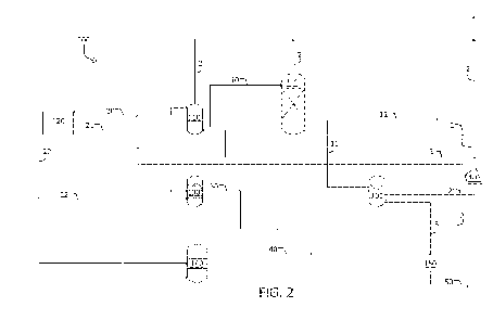
[0027] FIG. 2 is a process-flow diagram showing primary features of
one
embodiment of the acid gas removal unit having a first stage utilizing
hypochlorite and
bicarbonate and a second stage utilizing sodium hydroxide to make the
bicarbonate. The
process-flow diagram further shows how the units are integrated so that
products of one unit
can be the reactants for another unit(s).
[0028] FIGS. 3a and 3b show the results of a H2S removal study,
namely, a plot of
the percentage of H2S removal over time and the temperature of the absorption
liquid over
time, respectively.
5
CA 02937108 2016-07-15
WO 2015/109190
PCT/US2015/011765
[0029] FIGS. 4a and 4b show the study parameters and results,
respectively, of a
NO, removal study.
DETAILED DESCRIPTION
[0030] The present invention relates to at least a two-stage
absorption processes in
which an acid gas or acid gases, such as CO2, H2S, NOR, and/or SO,,, are
removed from a gas
stream and converted into a carbonate, a bicarbonate, a sulfate, or a nitrate.
Embodiments of
the methods and apparatuses of the present disclosure comprise one or more of
the following
general components: (1) an aqueous decarbonation process whereby gaseous CO2
is absorbed
into an aqueous caustic mixture and then reacted with a hydroxide to form
carbonate and/or
bicarbonate products; (2) a separation process whereby the carbonate and/or
bicarbonate
products are separated from the liquid mixture; (3) a brine electrolysis
process for production
of the sodium hydroxide that is used in the absorbent fluid in the
decarbonation process; (4)
an aqueous oxidization process whereby an acid gas is absorbed into the
aqueous oxidizing
mixture and then reacted with a hypochlorite and a bicarbonate to form a
sulfate and/or
nitrate product; (5) a separation process whereby the sulfate and/or nitrate
products generated
in the oxidation process are extracted from the aqueous mixture; (6) a
hypochlorite
generation process for production of the hypochlorite that is used as part of
the aqueous
oxidizing mixture; and (7) further processing or utilization of by-products
from the
decarbonation, oxidation, and electrolysis processes, including chlorine gas,
hydrogen gas,
hydrochloric acid, carbonate and bicarbonate, nitrates, sulfates, and bleach.
Each of these
general components is explained in further detail below.
100311 While many embodiments of the present invention consume some
energy to
accomplish the absorption of acid gases from a gas stream and to accomplish
the other
objectives of embodiments of the present disclosure as described herein, one
advantage of
certain embodiments of the present disclosure is that they provide ecologic
efficiencies that
are superior to those of the prior art, while absorbing most or all of the
acid gases, including
at least one or any combination of CO2, H2S, SON, and NON.
[0032] Unlike other processes in the art, certain embodiments
sequester carbon-
dioxide and other acid gases into economically useful chemicals and co-
incidentally produce
useful by-products such as sodium carbonate, sodium bicarbonate, sodium
hypochlorite,
chlorine gas, hydrochloric acid, and hydrogen gas. Because the by-products of
the described
processes are economically useful, those values offset the costs of acid gas
removal and, in
properly designed systems, potentially make the sequestration process
profitable in itself.
Moreover, unlike other processes in the art, the sequestration of CO2
generates byproducts
6
CA 02937108 2016-07-15
WO 2015/109190
PCT/US2015/011765
that can be utilized to sequester other acid gases, also adding to the cost
and ecological
efficiency.
100331 Another additional benefit of certain embodiments of the
present disclosure
that distinguishes them from other CO2-removal processes is that in some
market conditions,
the products are worth considerably more than the reactants required or the
net-power or
plant-depreciation costs. In other words, certain embodiments are industrial
methods of
producing chlor-hydro-carbonate products as well as nitrate and/or sulfate
products at a
profit, while accomplishing considerable removal of acid gases.
I. Flow Diagram: Absorption of Acid Gases Utilizing
Hypochlorite/Bicarbonate
[0034] FIG. 1 depicts a simplified process-flow diagram illustrating
general,
exemplary embodiments of the apparatuses and methods of the present
disclosure. This
diagram is offered for illustrative purposes only, and thus it merely depicts
specific
embodiments of the present disclosure and is not intended to limit the scope
of the claims in
any way.
[0035] In the embodiment shown in FIG. 1, the gas stream 2 to be scrubbed
enters
System 100 at a Hypochlorite/Bicarbonate Scrubber 105. Scrubber 105 is
configured to
remove (e.g., reduce the concentration of) acid gases comprising sulfur
containing
compounds and/or nitrogen containing compounds from gas stream 2, utilizing
hypochlorite
and bicarbonate as the reactants. The acid gases removed from gas stream 2
through such
process can include at least one of H2S, NOR, SON, and combinations thereof.
Examples of
the possible chemical reactions occurring in Scrubber 105 include the
following.
H2S:
H2S(g) + 4NaC10(aq)---->H2SO4(aq) + 4NaCl(aq)
(1)
H2SO4(aq) + 2NaHCO3(aq)¨>Na2SO4(aq) + 2CO2(aq) + 2H20(1)
(2)
SOS:
2S02(g) + 2H20(1) + 02(0¨>2H2SO4(aq) (3)
S03(g) + H20(1)-->H2SO4(aq)
(4)
H2SO4(aq) + 2NaHCO3(aq)¨>Na2SO4(aq) + 2CO2(g) + 21-120(1)
(5)
N Os :
NO(g) + NaC10 (aq)--->NaCl(aq) + NO2 (g)
(6)
2N0 (g) + 3NaCIO (aq) + H2 0 (1)-->3NaCl(aq) + 2HNO3 (aq) (7)
2NO2(g) + NaC10 (aq) + H2 0(1)--->NaCl(aq) + 2HNO3 (aq)
(8)
HNO3 (aq) + NaHCO3(aq)-->NaNO3 (aq) + CO2 (g) + H20(1)
(9)
7
CA 02937108 2016-07-15
WO 2015/109190
PCT/US2015/011765
2NO2(g) + 2NaHCO3(aq)--->NaNO3(aq) + NaNO2(aq) + 2CO2(g) +
H20(1) (10)
NaNO2(aq) + NaC10(aq)--->NaNO3(aq) + NaCl(aq)
(11)
[0036]
Scrubber 105 can be any wet scrubbing configuration suitable to bring the
gas
stream 2 into contact with the liquid phase containing hypochlorite and
bicarbonate, so as to
effectively reduce the amount of nitrogen and sulfur containing compounds
present in gas
stream 2. In the embodiment shown, the bicarbonate and hypochlorite reactants
are delivered
to Scrubber 105 separately, such as via lines 11 and 30, respectively. In
various
embodiments, Scrubber 105 can be a packed or unpacked bubble column. In the
embodiment
shown, Scrubber 105 comprises a set of downcomers 106 configured to create a
recirculation
loop to recirculate the liquid phase containing hypochlorite and bicarbonate.
In some
embodiments, System 100 can comprise two Scrubbers 105 and gas stream 2 can be
selectively routed to either one or both. In some embodiments, the liquid
phase in one of the
Scrubbers 105 may be substantially replaced with fresh reactor solution, while
gas stream 2 is
passing through the other Scrubber 105. The nitrate, sulfate, and or
bicarbonate products
produced in Scrubber 105 can be transported for further processing or storage,
such as via
line 5.
[0037] In
advance of entering Scrubber 105, if desired, gas stream 2 can be processed
to remove any heavy metals, particulates, and residual water content, e.g., in
Knockout Tank
103. Such processing may be needed when the gas stream is a natural gas or a
flue gas
stream. In various embodiments, Knockout Tank 103 can be configured to remove
heavy
metals, particulates by spraying a stream of a dilute hydroxide solution in
Knockout Tank
103 that mixes with gas stream 2. The concentration of the hydroxide solution
can be 0.5%,
1%, 1.5%, 2%, 2.5%, 3%, 3.5% by wt. or any value therebetween. A portion of
the acid
gases, particularly the sulfur-based acid gases, may also be removed in this
process. In other
embodiments, such as the one shown in FIG. 2 described below, Knockout Tank
103 can be
located after the Scrubber 105 to remove residual sulfur-containing and
nitrogen-containing
acid gases in gas stream 2 prior to it entering into Columns 110/111 as
described below.
IL Flow Diagram: Absorption of Carbon Dioxide and Other Acid Gases
[0038]
FIG. 2 depicts a simplified process-flow diagram illustrating general,
exemplary ,embodiments of the apparatuses and methods of the present
disclosure. This
8
CA 02937108 2016-07-15
WO 2015/109190
PCT/US2015/011765
diagram is offered for illustrative purposes only, and thus it merely depicts
specific
embodiments of the present invention and is not intended to limit the scope of
the claims in
any way.
[0039]
In the embodiment shown in FIG. 2, the gas stream 2 to be scrubbed and
decarbonated enters system 200 at a Hypochlorite/Bicarbonate Scrubber 105,
such as the one
described above. CO2, which is a byproduct of this scrubbing process (see,
e.g., equations
(2), (5), (9), and (10)), becomes part of gas stream 2 exiting Scrubber 105.
Thus, in various
embodiments, exiting gas stream 2 can potentially comprise both CO2 originally
present in
the gas stream and CO2 byproduct generated by the process in Scrubber 105. In
other
embodiments, gas stream 2 may only comprise the CO2 byproduct.
[0040]
Gas stream 2 flowing from Scrubber 105 can be differentially introduced into
Absorption/Carbonation Column 110 or Bubble/Bicarbonation Column 111,
configured in
series. In the depicted embodiment, hydroxide from Chlor-alkali Cell 120 can
be transferred
to Absorption/Carbonation Column 110, such as via line 20, to react with
carbon dioxide
present in the portion of gas stream 2 introduced into Absorption/Carbonation
Column 110
according to the reaction represented by equation 12.
In some embodiments, the
concentration of the hydroxide solution generated in the Chlor-alkali Cell 120
can be diluted
to a preferred concentration prior to introducing into the Chlor-alkali Cell
120.
2 NaOH + CO2 ¨> Na2CO3 + H2O (12)
[0041]
A portion of the liquid phase comprising sodium carbonate from
Absorption/Carbonation Column 110 is transported, such as via line 10, to
Bubble/Bicarbonation Column 111 to cause conversion of carbonate to
bicarbonate by
reaction with residual CO2 in the liquid phase, as represented by equation 13.
In the depicted
embodiment, at least a portion of the bicarbonate generated in Column 111 is
transported to
Scrubber 105, such as via line 11, to be consumed, for example, according to
reactions (2),
(5), (9), and (10).
Na2CO3+ CO2 + H20 --> 2NaHCO3 (13)
[0042]
The process of decarbonation occurring in Absorption/Carbonation Column
110 and Bubble/Bicarbonation Column 111 can be further modified, optimized and
scaled up
9
CA 02937108 2016-07-15
WO 2015/109190
PCT/US2015/011765
using the principles and techniques of chemistry, chemical engineering, and/or
materials
science as applied by a person skilled in the art and taught, for example, in
U.S. Patent
7,727,374, which is hereby incorporated by reference in its entirety.
[0043] After passing through Scrubber 105 and one or both of Columns
110 and 111,
the gas stream has significantly reduced levels of acid gases. Gas stream 2
can then proceed
to the next step, which will depend on the specific application within which
this described
process is being utilized. For example, an industrial process gas stream may
require further
cleaning or be directly discharged into the atmosphere. In other embodiments,
such as in the
context of cleaning a natural gas stream, the gas stream can be transported
for use at another
location, utilized in power generation, or stored for later use.
[0044] Supporting processes and apparatuses are integrated into
System 200 to
generate additional reactants for the above-described absorption processes and
include a
Chlor-alkali Cell 120 and a Hypochlorite Reactor 130. Chor-alkali Cell 120
uses power to
drive a reaction represented by equation 14.
2 NaC1+ 2 H20 2 NaOH + C12 + H2 (14)
[0045] The sodium hydroxide generated in Cell 120 can be delivered,
such as via line
20, to either or both Absorption/Carbonation Column 110 and Hypochlorite
Reactor 130. At
least a portion of the chlorine, also from Chlor-alkali Cell 120, is
delivered, such as via line
22, to either or both Hypochlorite Reactor 130 and HC1 Burner 140.
[0046] In Hypochlorite Reactor 130, at least a portion of the
chlorine is contacted
with (e.g., bubbled through) at least a portion of the alkali hydroxide to
produce a
hypochlorite solution according to reaction 15. At least a portion of the
hypochlorite solution
can be fed into Scrubber 105, such as via line 30. The sodium hypochlorite not
needed for
Scrubber 105 can be trucked to market as salable bleach.
2 NaOH + C12 Na0C1+ NaCl + H20. (15)
100471 To capture the chlorine gas generated in the Chlor-alkali Cell 120
and not used
in the Hypochlorite Reactor 130, the chlorine and hydrogen produced from the
Chlor-alkali
Cell 120 can be delivered to an HC1 Burner 140, such as via lines 22 and 21,
respectively to
CA 02937108 2016-07-15
WO 2015/109190
PCT/US2015/011765
produce hydrogen chloride. The generated HC1 can be transferred to a tank for
storage or
transport via line 40. The net reaction can be represented by equation 16:
C12 + H2 ----> 2 HC1 (16)
[0048] In the embodiment shown, after Scrubber 105, gas stream 2 is
processed to
remove residual SO, and NO, acid gases, e.g., in Knockout Tank 103. For
example,
Knockout Tank 103 can be configured to absorb residual SO, and NO, by spraying
a stream
of a dilute hydroxide solution in Knockout Tank 103 that mixes with gas stream
2. The
concentration of the dilute hydroxide stream can be 0.5%, 1%, 1.5%, 2%, 2.5%,
3%, 3.5% by
wt. or any value therebetween. In the depicted embodiment, the hydroxide in
the dilute
hydroxide solution is generated in Chlor-Alkali Cell 120.
[0049] At least a portion of the reacted liquid phase from Scrubber
105 containing
nitrates and/or sulfates, such as NaNO3 and/or NaSO4, can be transferred, such
as via line 5,
to Fertilizer Generating Unit 150. In Unit 150, the liquid phase from Scrubber
105 can be
reacted with ammonia to generate ammonium sulfate and/or ammonium nitrate
according to
equations 17 and 18 provided below. The liquid/solid phase products of
equations 17 and/18
can be transferred for further processing or storage, such as via line 50.
Like System 100,
System 200 can comprise two Scrubbers 105 and gas stream 2 can be selectively
routed to
either one or both. In some embodiments, dual Scrubbers 105 can facilitate
transfer of the
liquid phase to Unit 150 and replenishment of the absorption fluid.
[0050] Through the above-described process, the bicarbonate by-
product generated
from decarbonation can be utilized along with hypochlorite to scrub the gas
stream of a
variety of acid gases in Scrubber 105, and the generated CO2 as a result of
the scrubbing with
the bicarbonate can be recaptured by the decarbonation process. In addition,
many of the
generated by-products can be sold for economic gain, such as, sodium
hypochlorite and
sodium bicarbonate. The sulfate and nitrate byproducts can be easily disposed
of or can be
further processed to generate fertilizer for economic gain.
[0051] These methods and devices can be further modified, optimized
and scaled up
using the principles and techniques of chemistry, chemical engineering, and/or
materials
science as applied by a person skilled in the art. Such principles and
techniques are taught,
for example, in U.S. Patent Application Publications 2006/0185985 and
2009/0127127, U.S.
Patent No. 7,727,374, filed September 22, 2005, U.S. Provisional Patent
Application No.
11
CA 02937108 2016-07-15
WO 2015/109190
PCT/US2015/011765
60/718,906, filed September 20, 2005; U.S. Provisional Patent Application No.
60/642,698,
filed January 10, 2005; U.S. Provisional Patent Application No. 60/612,355,
filed September
23, 2004, U.S. Patent Application No. 12/235,482, filed September 22, 2008,
U.S.
Provisional Application No. 60/973,948, filed September 20, 2007, U.S.
Provisional
Application No. 61/032,802, filed February 29, 2008, U.S. Provisional
Application No.
61/033,298, filed March 3, 2008, International Application No. PCT/US08/77122,
filed
September 19, 2008, and U.S. Patent Publication No. 2013/0202516, filed
January 11, 2013.
The entire text of each of the above-referenced disclosures (including any
appendices) is
specifically incorporated by reference herein without disclaimer.
[0052] The above examples were included to demonstrate particular
embodiments of
the invention. However, those of skill in the art should, in light of the
present disclosure,
appreciate that many changes can be made in the specific embodiments which are
disclosed
and still obtain a like or similar result without departing from the spirit
and scope of the
invention.
III. Aqueous Sequestration (Absorption) of Acid Gases from Gas Streams and
Its
Conversion into Nitrates and/or Sulfates
[0053]
As noted above, in certain embodiments, the apparatuses and methods of the
present disclosure employ an aqueous sequestration process whereby an acid gas
is absorbed
into an aqueous caustic mixture where it then reacts with the hypochlorite and
bicarbonate to
form sulfate and/or nitrate products. In embodiments of the present
disclosure, sodium
hypochlorite and sodium bicarbonate are used as the scrubbing reagents. When
an acid gas is
brought into contact with aqueous sodium hypochlorite and aqueous sodium
bicarbonate, the
resulting products depend on the composition of the gas stream. In general,
the products
include sodium nitrate (NaNO3) and sodium sulfate (Na2SO4). In some
embodiments of the
present disclosure, most of the sulfur-based acid gases and nitrogen-based
acid gases are
reacted in this manner, e.g., at least 70%, 75%, 80%, 85%, 90%, 91%, 92%, 93%,
94%, 95%,
96%, 97%, 98%, 99%, 99.1%, 99.2%, 99.3%, 99.4%, 99.5%, 99.6%, 99.7%, 99.8%, or
99.9% of the acid gases are reacted in this manner.
100541
The process conditions and amount of reagents can be varied based on the
composition of the gas stream, whether it only comprises sulfur-based acid
gases, only
nitrogen-based acid gases, or some combination thereof Generally, the
concentrations of
sodium hypochlorite and sodium bicarbonate can each be between 0.1% to about
12% by
weight, such as 0.6%, 0.7%, 0.8%, 0.9%, 1%, 1.5%, 2%, 2.5%, 3%, 3.5%, 4%,
4.5%, 5%,
12
CA 02937108 2016-07-15
WO 2015/109190
PCT/US2015/011765
5.5%, 6%, 6.5%, 7%, 7.5%, 8%, 8.5%, 9%, 9.5%, 10%, 10.5%, 11%, 11.5%, or any
value or
range therebetween. For example, in certain embodiments, the sodium
hypochlorite
concentration is about 0.5% to about to about 6% by weight, to about 5% by
weight, to about
4% by weight, or to about 3% by weight. Similarly, in certain embodiments, the
sodium
bicarbonate concentration is about 0.5% to about 8% by weight, to about 7% by
weight, to
about 6% by weight, to about 5% by weight, to about 4% by weight, or to about
3% by
weight. In addition, in various embodiments, the molar ratio of hypochlorite
to bicarbonate
can be between about 5:1 to about 1:1, such as about 4:1, 3:1, or 2:1. For
example, the molar
ratio of hypochlorite to bicarbonate can be between about 2:1 to about 5:1 or
to about 4:1.
The pH of the liquid phase within Scrubber 105 can be neutral to basic, such
as between a pH
of about 7, 7.5, 8, 8.5, 9, 9.5, 10, 10.5, 11 or any value or range
therebetween.
[0055] The formation of nitrate and/or sulfate products can occur
over a wide range
of temperatures and pressures. With respect to temperature, by way of example,
the
incoming gas can be between about 20 C to about 140 C and the incoming liquid
reagent
feed(s) can be between about 10 C to about 100 C. Also, by way of example, the
headspace
pressure in the absorption column can be between about 1 atm to about 3 atm.
[0056] In various embodiments, Scrubber 105 can be a spray-tower, a
packed or
unpacked bubble column or a series thereof, or any other mixing configuration
suitable to
bring the absorbent solution(s) into effective contact with the gas stream.
[0057] A bench scale study of sequestering H2S with a hypochlorite-
bicarbonate
solution was performed using a gaseous mixture of H2S and CO2 and bubbling it
through the
solution. The results of the study demonstrate efficacy and provide insight
into how the
concentrations and relative ratios of hypochlorite and bicarbonate affect
sequestration. The
test parameters and results are shown in Tables 1 and 2 below. FIG. 3a plots
the percent of
H2S removal over time and FIG. 3b plot the temperature of the liquid phase.
After 2.5 hours
of run time, the percentage of H2S removed from the gas begins to decline as
does the
temperature. This is likely due to a diminished concentration of hypochlorite,
as this data
was generated on a test run in batch mode.
Table 1 ¨ 4" Column Composition
Compound Quantity
NaHCO3 251.98 g (6.38 %wt)
NaCIO (8.25%) 1,946.67 (159.34)g (4.04% wt)
H20 1,748.65 g
1-,
CA 02937108 2016-07-15
WO 2015/109190
PCT/US2015/011765
Table 2 ¨ Run Results
Time After mol% mol% mol% %H2S Removed
Sample
Start CO2 N2 H2S
0 5.52
1 0:30 12.59 1.12 0.0037 99.93
2 1:30 18.74 0.62 0.0036 99.93
3 2:30 16.34 0.67 0.0029 99.95
4 3:30 13.48 2.02 0.92 83.41
5 4:30 12.07 0.29 2.33 57.83
6 5:00 11.95 0.91 2.82 48.84
[0058] A bench scale study of sequestering NO, with a hypochlorite-
bicarbonate
solution was also performed using various gaseous mixtures containing NO, NO2,
SO2,
5 and/or CO2 and bubbling the gas mixture through the solution. The results
of the study show
that different combinations of gasses and different concentrations of
hypochlorite and
bicarbonate can greatly affect the overall reactivity of the NO molecule and
that the specific
composition of the reactor may be tailored to some extent by the composition
of the gas
stream that is being treated. The test parameters and results of the study are
shown in the
10 tables in FIGS. 4a and 4b, respectively. The results of the study
demonstrate efficacy and
provide insight into how the concentrations and relative ratios of
hypochlorite and
bicarbonate affect sequestration. The solutions with higher strength bleach
and a higher gas
flow tended to capture more NO, likely due to better contacting between the
bleach and the
NO.
[0059]
While the described Scrubber 105 embodiments use sodium hypochlorite,
those of ordinary skill will understand that it is possible to obtain similar
chemistry and
oxidation with any number of hypochlorites or mixtures thereof, including but
not limited to
potassium hypochlorite, calcium hypochlorite, and magnesium hypochlorite.
Similarly,
described embodiments also use sodium bicarbonate, yet those of ordinary skill
will
understand that it is possible to obtain similar chemistry and oxidation with
any number of
carbonates, bicarbonates or mixtures of carbonates and/or bicarbonates,
including but not
limited to sodium carbonate, sodium bicarbonate, potassium carbonate,
potassium
bicarbonate, calcium carbonate, calcium bicarbonate, magnesium carbonate, and
magnesium
bicarbonate,.
IV.
Aqueous Decarbonation (Absorption) of CO2 from Gas Streams and Its
Conversion into Carbonate and Bicarbonate
14
CA 02937108 2016-07-15
WO 2015/109190
PCT/US2015/011765
[0060]
As noted above, in certain embodiments, the apparatuses and methods of the
present disclosure employ an aqueous decarbonation process via
Absorption/Carbonation
Column 110 and Bubble/Bicarbonation Column 111, whereby gaseous CO2 is
absorbed into
an aqueous caustic mixture where it then reacts with the hydroxide to form
carbonate and
bicarbonate products. In many embodiments of the present disclosure, sodium
hydroxide is
used as the primary absorbent fluid. Sodium hydroxide, in various
concentrations, is known
to readily scrub CO2. When carbon dioxide is brought into contact with aqueous
sodium
hydroxide, a range of products from pure sodium bicarbonate (NaHCO3) to pure
sodium
carbonate (Na2CO3) can be formed, and differing conditions can be produced
that will drive
the equilibrium in either direction. In some embodiments of the present
disclosure, most or
nearly all of the carbon dioxide is reacted in this manner. In some
embodiments, the reaction
may proceed to completion (or its near vicinity) and sufficient concentration
of the desired
carbonate product may be achieved (by either process chemistry or removal of
water by
various means) in order to cause precipitation of bicarbonate, carbonate, or a
mixture of both.
[0061] In some embodiments, when carbon dioxide is brought into contact
with
aqueous sodium hydroxide, the fluid within the reaction columns approximates
the behavior
shown in equation 13. The two reaction process that take place are:
1. An initial absorption phase in which CO2 is readily absorbed: As CO2
enters
the liquid, it absorbs into the fluid to form carbonic acid, which then reacts
with
hydroxide. The absorption ability of the fluid declines as the OH-
concentration
declines, and absorption ends and in some instances reverses when the OH-
concentration is consumed. The reaction, shown in equation 12 above, is
exothermic
during this portion and forms almost exclusively carbonate.
2. A secondary conversion phase in which CO2 is absorbed, but less
favorably
than the previous step. As CO2 enters the liquid, it forms carbonic acid. This
carbonic acid then reacts with the entering carbonate solution, forming a
sodium
bicarbonate solution by the following net stoichiometry:
Na2CO3(aq) + H20(1) + CO2 (aq) ----> 2 NaHCO3(aq) (13)
[0062]
In various embodiments, as illustrated in FIG. 2, the formation of
bicarbonate
occurs in two separate columns, with one column being used to produce sodium
carbonate
and the other chamber being used to produce sodium bicarbonate. In various
embodiments,
CA 02937108 2016-07-15
WO 2015/109190
PCT/US2015/011765
each chamber can be a spray-tower, a packed or unpacked bubble column or a
series thereof,
or any other mixing configuration suitable to bring the hydroxide solution or
carbonate
solution in effective contact with the gas stream for absorption to carbonate
in the case of
Column 110 and conversion to bicarbonate in the case of Column 111.
[0063] In various embodiments of the present disclosure, a broad range in
the amount
of bicarbonate/carbonate/caustic/bleach/other desirable products may be
produced in the
overall system. However, the amount of bicarbonate required for scrubbing acid
gases is
dependent on the composition of the gas stream. In certain embodiments, higher
concentrations of sulfur-based and/or nitrogen-based acid gases can require
more sodium
bicarbonate to be directed to Scrubber 105, and conversely, lower
concentrations require less.
[0064] These methods and devices can be further modified, optimized
and scaled up
using the principles and techniques of chemistry, chemical engineering, and/or
materials
science as applied by a person skilled in the art. Such principles and
techniques are taught,
for example, in U.S. Patent No. 7,727,374, filed September 22, 2005, U.S.
Provisional Patent
Application No. 60/718,906, filed September 20, 2005; U.S. Provisional Patent
Application
No. 60/642,698, filed January 10, 2005; U.S. Provisional Patent Application
No. 60/612,355,
filed September 23, 2004, U.S. Patent Application No. 12/235,482, filed
September 22, 2008,
U.S. Provisional Application No. 60/973,948, filed September 20, 2007, U.S.
Provisional
Application No. 61/032,802, filed February 29, 2008, U.S. Provisional
Application No.
61/033,298, filed March 3, 2008, International Application No. PCT/US08/77122,
filed
September 19, 2008, and U.S. Patent Publication No. 2013/0202516, filed
January 11, 2013.
The entire text of each of the above¨referenced disclosures (including any
appendices) is
specifically incorporated by reference herein without disclaimer.
V. Separation of Products
[0065] With regard to the Column 110 and/or 111 liquid stream, the
formation of
sodium hydrogen carbonate (NaHCO3 or sodium bicarbonate) and sodium carbonate
(Na2CO3 or soda ash) occurs over a wide range of temperatures and pressures
and provides
different end-points of the equilibrium given different partial pressures of
CO2. By
manipulating one or more of the basic concentration, reagent and/or gas flow
rates,
temperature, pressure, and fluid depth, formation of carbonate and/or
bicarbonate precipitants
may occur. In various embodiments, the reagent flow rates and/or the gas flow
rates can be
altered to cause the formation of carbonate and/or bicarbonate precipitants.
Moreover,
carbonate/bicarbonate precipitants may be separated from the liquid phase or
dried by
16
CA 02937108 2016-07-15
WO 2015/109190
PCT/US2015/011765
mechanical separation (e.g., a centrifuge) and/or the exchange of heat energy
with incoming
gases, in some embodiments. Alternatively or in addition thereto, in certain
embodiments the
heat for the separation process may be derived from the hydrogen produced in
the original
electrolysis.
[0066] The exiting liquid stream from the Column 110 and/or 111, depending
upon
absorber/system design, may include water, NaHCO3, Na2CO3, and other dissolved
gases in
various equilibria. In one embodiment, to separate/remove the exiting liquid
streams, e.g.,
removing/separating the water from the carbonates (in this sense of the word,
"carbonates"
means mixtures of carbonate and bicarbonate) may include mechanical separation
(such as
centrifuge separation) and/or adding heat energy to evaporate water from the
mixture. In
other embodiments, pure carbonate, pure bicarbonate, and mixtures of the two
in equilibrium
concentrations and/or in a slurry or concentrated form may then be
periodically transported to
storage tanks and/or trucks/tank-cars. In other embodiments, the liquid
streams may be
displaced to evaporation tanks/fields, where the liquid, such as water, may be
carried off by
evaporation.
[0067] In a precipitation method according to certain embodiments of
the present
disclosure, the water in the liquid phase binds carbon dioxide, causing the
gas to be absorbed
on contact, with a substantially instantaneous conversion to carbonate ion.
This phase of the
reaction chain may be mass-transport limited such that once the carbon-dioxide
has been
absorbed, the subsequent ionic reaction occurs at rapid pace. However, for the
formation of
bicarbonate, the reaction is reaction rate limited. Therefore, a system that
separates these two
phases as described herein can be more efficient, particularly for obtaining
higher purity
precipitants.
[0068] With regard to Scrubber 105 liquid stream, the composition of
the exiting
liquid stream from Scrubber 105 largely depends on the contents of the gas
stream. The
exiting liquid stream may include water, Na2SO4, NaNO3, NaC1, Na0C1, NaHCO3,
and other
dissolved gases in various equilibria.
[0069] In one embodiment, to separate/dispose of the exiting liquid
streams, e.g.,
removing/separating the water from the nitrates and sulfates, can involve
heating the liquid to
evaporate the water. In another embodiment, the sulfate can be isolated by
passing the liquid
stream through a sulfate recovery process that separates sulfates from NaCl
and then add
CaCl2 to convert the Na2SO4 to CaSO4, which precipitates. Similarly, in other
embodiments,
the aqueous phase can be reacted with ammonia to generate ammonium sulfate
and/or
ammonium nitrate according to equations 17 and 18, such as in Fertilizer
Generating Unit
17
CA 02937108 2016-07-15
WO 2015/109190
PCT/US2015/011765
150. In this manner, bicarbonate can be regenerated. In addition, the ammonium
sulfate
and/or ammonium nitrate products can be utilized as a fertilizer.
Na2SO4(aq) + 2NH3(aq) + 2H20(1) + 2CO2(g)-->(NH4)2SO4(aq) + 2NaHCO3(s)
(17)
NaNO3(aq) + NH3(aq) + H20(1) + CO2(g)-->NH4NO3(aq) + NaHCO3(s)
(18)
[0070] In other embodiments, the liquid streams may be displaced to
evaporation
tanks/fields, where the liquid, such as water, may be carried off by
evaporation.
VI. Electrolysis for the Production of Absorbent Fluids At Low Energies
[0071] As noted above, in certain embodiments, the apparatuses and
methods of the
present disclosure employ a Chlor-alkali Cell 120 for production of the sodium
hydroxide
that is used as the absorbent fluid in the decarbonation process. Chlor-alkali
electrolysis is an
electrochemical process primarily used in the production of concentrated
sodium hydroxide
(caustic soda) and chlorine gas, and is typically described throughout the
relevant literature
by equation 14:
2 NaCI +2 H20 ---> 2 NaOH + H2 C12 (14)
[0072] Such electrolysis is typically accomplished by three general
types of standard
electrolysis cells: diaphragm, mercury, and membrane cells. Each of these
types of cells
produces the same output products from the same input reactants. They differ
from each
other primarily in the way the reactants and products are separated from each
other.
[0073] In one embodiment, a membrane cell may be used due to several
factors.
First, environmental concerns over mercury have reduced the demand for the
mercury cell.
Second, the diaphragm cells may produce a relatively weak caustic product
which contains
significant concentrations of salt and chloride ion and requires considerable
subsequent
reprocessing/separation to remove the significant salt content from the
caustic. Third,
improvements in fluorinated polymer technology have increased the life-time
and electrical
efficiency of membrane cell technology, where membrane lifetimes in excess of
five years
are routinely guaranteed in the industrial markets. Further, the power-per-ton-
of-caustic
efficiencies exceed those of both diaphragm and mercury cells in preferred
implementations.
18
CA 02937108 2016-07-15
WO 2015/109190
PCT/US2015/011765
[0074] Many preferred embodiments may employ membrane cells in this
function.
Membrane cells have several advantages over other chlor-alkali electrolysis
processes. First,
membrane cells neither contain nor produce any environmentally sensitive
emissions (e.g.,
mercury) and are electrically efficient when compared with diaphragm and
mercury cells.
They also employ a concentrated/dilute/make-up NaC1 loop such that they may be
well-suited
for use as a continuous "salt loop" processing unit. Next, NaOH produced in
membrane cells
without further evaporation/concentration may be a naturally appropriate level
of
concentration for use in a decarbonation process (e.g., 30-33% NaOH by
weight). Membrane
cell technology may also be easily scaled from laboratory to plant-size
production by the
addition of small incremental units.
[0075] Further, hydrogen produced by membrane cells is "clean,"
approximately
"electronic grade," and relatively clear of NaC1 or other contamination. As
such, hydrogen
may be compressed and tanked off as electronic-grade H2 gas, used for power-
production on-
site such as combustion mix with low-grade coal or for combustion-technology
gains.
Alternatively, the hydrogen may be used for a boiler fuel for the separation
processes.
Additionally, chlorine gas produced by the membrane process is less "wet" than
that
produced by other standard electrolytic processes. As such, a one-stage
compression cycle
may be sufficient for production of water-treatment grade chlorine.
[0076] In certain embodiments, acid is added to the solution before
it is electrolyzed.
The acid can be any form of acid that can provide protonation to the solution,
including but
not limited to hydrochloric acid. Those of ordinary skill will understand that
it is possible to
obtain similar chemistry and electrolysis with any number of acids or mixtures
of acids. In
some embodiments, the acid is hydrochloric acid generated in Burner 140
through the
combustion of byproducts, H2 and C12. The amount of acid added to the solution
can be
based on a determination of the optimum protonation rate that achieves the
lowest energy to
produce reactants and the highest energy to recover from products.
[0077] These methods and devices can be further modified, optimized
and scaled up
using the principles and techniques of chemistry, chemical engineering, and/or
materials
science as applied by a person skilled in the art. Such principles and
techniques, including
techniques for using low-voltage electrolysis (LVE) to improve the
thermodynamic
efficiency of the process, are taught, for example, in U.S. Patent No.
7,727,374, filed
September 22, 2005, U.S. Provisional Patent Application No. 60/718,906, filed
September
20, 2005; U.S. Provisional Patent Application No. 60/642,698, filed January
10, 2005; U.S.
Provisional Patent Application No. 60/612,355, filed September 23, 2004, U.S.
Patent
19
CA 02937108 2016-07-15
WO 2015/109190
PCT/US2015/011765
Application No. 12/235,482, filed September 22, 2008, U.S. Provisional
Application No.
60/973,948, filed September 20, 2007, U.S. Provisional Application No.
61/032,802, filed
February 29, 2008, U.S. Provisional Application No. 61/033,298, filed March 3,
2008,
International Application No. PCT/US08/77122, filed September 19, 2008, and
U.S. Patent
Publication No. 2013/0202516, filed January 11,2013. The entire text of each
of the above¨
referenced disclosures (including any appendices) is specifically incorporated
by reference
herein without disclaimer.
VII. Production of Hypochlorite
[0078] As noted above, in certain embodiments, the apparatuses and
methods of the
present disclosure employ a Hypochlorite Reactor 130. Chlorine gas generated
in the chlor-
alkali process in Cell 120 is collected and moved to Hypochlorite Reactor 130
and/or HC1
Burner 140. The chlorine gas delivered to Hypochlorite Reactor 130 is
contacted (bubbled)
through a sodium hydroxide solution delivered directly or indirectly from
Chlor-alkali Cell
120. Sodium hypochlorite solution results and can be used as the absorbent
solution, along
with a bicarbonate solution generated in Conversion/Bicarbonation Column 111,
in Scrubber
105 and/or trucked to market.
VIII. Recovery of Waste-Heat
[0079] Because certain embodiments of the present disclosure are
employed in the
presence of a power-plant or large emission of CO2 in the form of flue-gas or
other hot gases
from combustion, there may be ample opportunity to utilize this 'waste' heat
in the
optimization of the electro-chemical cell, unlike standard chlor-alkali
processes. For
instance, a typical incoming flue-gas temperature (after electro-static
precipitation treatment,
for instance) might well be 300 C. A system in accordance with the present
disclosure can
comprise heat exchangers adapted to lower that flue-gas to a point less than
300 C, while
warming the anolyte and catholyte fluids (which, for LVE, should generally be
retained
>87.5 C). This facilitates operation without the power-losses associated with
anolyte and
catholyte heaters.
[0080] Generally, since the flue-gas available at power-plant exits
at temperatures
between 100 C (scrubbed typical), 300 C (after precipitation processing), and
900 C
(precipitation entrance), or other such temperatures, considerable waste-heat
processing can
be extracted by cooling the incoming flue-gas through heat-exchange with a
power-recovery
cycle, of which an example is an ammonia-water cycle ("Kalina" cycle, for
example), a steam
CA 02937108 2016-07-15
WO 2015/109190
PCT/US2015/011765
cycle, or any such cycle that accomplishes the same thermodynamic means. Since
some
embodiments of the present disclosure rely upon DC power to accomplish the
manufacture of
the reagent/absorbent for the present disclosure, the process can be directly
powered, partially
or wholly, by waste-heat recovery that is accomplished without the normal
transformer losses
associated with converting that DC power to AC power for other uses. Further,
through the
use of waste-heat-to-work engines, significant efficiencies can be
accomplished without an
electricity generation step being employed at all. In some conditions, these
waste-heat
recovery energy quantities may be found to entirely power embodiments of the
present
disclosure.
[0081] Waste-heat recovery from other processes of the systems may also be
employed similarly to gain efficiencies at other points in the system.
[0082] The above specifications and examples provide a complete
description of the
structure and use of exemplary embodiments. Although certain embodiments have
been
described above with a certain degree of particularity, or with reference to
one or more
individual embodiments, those skilled in the art could make numerous
alterations to the
disclosed embodiments without departing from the scope of this disclosure. As
such, the
illustrative embodiments of the present apparatuses, systems, and methods are
not intended to
be limiting. Rather, the present devices, systems, and methods include all
modifications and
alternatives falling within the scope of the claims, and embodiments other
than those shown
may include some or all of the features of the depicted embodiments. For
example,
components may be combined as a unitary structure and/or connections may be
substituted.
Further, where appropriate, aspects of any of the examples described above may
be combined
with aspects of any of the other examples described to form further examples
having
comparable or different properties and addressing the same or different
problems. Similarly,
it will be understood that the benefits and advantages described above may
relate to one
embodiment or may relate to several embodiments.
[0083] The claims are not to be interpreted as including means-plus-
or step-plus-
function limitations, unless such a limitation is explicitly recited in a
given claim using the
phrase(s) "means for" or "step for," respectively.
21