Note : Les descriptions sont présentées dans la langue officielle dans laquelle elles ont été soumises.
CA 02937319 2016-07-27
DEPLOYMENT MECHANISM FOR INFLATABLE
SURFACE-INCREASING FEATURES FOR GAS TURBINE ENGINE
TECHNICAL FIELD
The application relates generally to gas turbine engines and, more
particularly, to turbine exhaust cases, fan ducts, or tabs nozzle therefor.
BACKGROUND OF THE ART
The exhaust jet of a gas turbine engine is a significant noise source,
particularly at high power conditions, which may drive the overall aircraft
noise
affecting communities surrounding airport and the cabin noise. Chevrons
located at
the trailing edge of nozzles have emerged as an effective means of reduction
of jet
noise for mid-to-high bypass ratio turbo-fan engines. The chevrons are
typically
shaped as saw-tooth patterns on the trailing edges of jet engine nozzles. The
chevron nozzles induce additional mixing mechanisms altering the shear layer
thereby promoting a rapid plume decay and resulting in noise reduction. This
may
however be accompanied by an increased drag which results in a deterioration
of
the performance of the gas turbine engine.
SUMMARY
In one aspect, there is provided a deployment mechanism for inflatable
surface-increasing features a gas turbine exhaust case comprising: a plurality
of
inflatable surface-increasing features adapted to be circumferentially
distributed
within the gas turbine exhaust case at a trailing edge thereof, the inflatable
surface-
increasing features being inflatable from a stowed configuration in which the
inflatable surface-increasing features are substantially concealed fore of the
trailing
edge, to a deployed configuration in which the inflatable surface-increasing
features
extend beyond the trailing edge; and a pressurizing system in fluid
communication
with the plurality of chevrons to inflate and deflate the inflatable surface-
increasing
features.
In a second aspect, there is provided a gas turbine engine comprising: a
turbine case defining an annular cavity; a plurality of inflatable surface-
increasing
features circumferentially distributed within the annular cavity at a trailing
edge
thereof, the inflatable surface-increasing features being inflatable from a
stowed
configuration in which the inflatable surface-increasing features are
substantially
concealed within the turbine case, to a deployed configuration in which the
inflatable
1
CA 02937319 2016-07-27
surface-increasing features extend outside the turbine case at the trailing
edge, and
a pressurizing system in fluid communication with the plurality of inflatable
surface-
increasing features to inflate and deflate the inflatable surface-increasing
features
between the stowed configuration and the deployed configuration.
In a third aspect, there is provided a method for deploying chevrons at a
trailing edge of a gas turbine exhaust case of an aircraft, comprising:
directing
pressurized fluid to a plurality of inflatable surface-increasing features at
the trailing
edge of the exhaust case; and inflating the plurality of inflatable surface-
increasing
features to a deployed configuration in which the inflatable surface-
increasing
features are inflated to extend beyond the trailing edge of the exhaust case.
Further details of these and other aspects of the present invention will be
apparent from the detailed description and figures included below.
DESCRIPTION OF THE DRAWINGS
Reference is now made to the accompanying figures, in which:
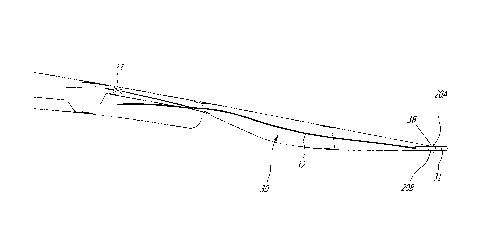
Fig. 1 is a schematic cross-sectional view of a turbofan gas turbine engine;
Figs. 2A and 2B are a schematic enlarged section view, and a schematic
end view, respectively, of a case of a gas turbine engine enclosing a chevron
deployment mechanism, with chevrons stowed;
Figs. 3A and 3B are a schematic enlarged section view, and a schematic
end view, respectively, of the case of the gas turbine engine enclosing the
chevron
deployment mechanism of Figs. 2A and 2B, with chevrons deployed;
Fig. 4 is a schematic rear view showing chevrons of the chevron
deployment mechanism of Fig. 2A connected to reinforcement members of an end
frame, in a stowed configuration and in a deployed configuration;
Fig. 5 is a schematic perspective view showing chevrons of the chevron
deployment mechanism of Fig. 2A connected to an inner skin and an outer skin,
in a
stowed configuration and in a deployed configuration; and
Fig. 6 is a schematic enlarged section view of a case of a gas turbine
engine enclosing a chevron deployment mechanism with a combination of rigid
and
flexible pressurizing lines.
2
CA 02937319 2016-07-27
DETAILED DESCRIPTION OF THE PREFERRED EMBODIMENTS
Fig.1 illustrates a turbofan gas turbine engine 10 of a type preferably
provided for use in subsonic flight, generally comprising in serial flow
communication a fan 12 in an outer case 13 through which ambient air is
propelled,
a multistage compressor 14 for pressurizing the air, a combustor 16 in which
the
compressed air is mixed with fuel and ignited for generating an annular stream
of
hot combustion gases, and a turbine section 18 in a turbine case 19 for
extracting
energy from the combustion gases.
Referring to Figs. 2A and 3A, a gas turbine engine case or nacelle that may
or may not include a thrust reverser is shown as having an outer skin 20, an
inner
skin 21, so as to define an inner cavity 22 therebetween. The engine case is
for
instance the outer case 13, although it is contemplated to provide the chevron
deployment mechanism described hereinafter in the turbine case 19 as well, as
the
chevrons may be useful in any of the exhaust cases of the gas turbine engine
10.
For simplicity, the expression "case" will be used hereinafter. The gas
turbine
engine case is annular, whereby the inner cavity 22 is annular, as observed
from
Figs 2B and 3B. An annular opening 23 is circumscribed by trailing edges 20A
and
21A of the outer skin 20 and of the inner skin 21. According to an embodiment,
the
outer skin 20 and the inner skin 21 are part of a thrust reverser, for
instance forming
an end frame pivotable at pivot frame 24, and separable from a remainder of
the
nacelle.
A chevron deployment mechanism is generally shown at 30, and is mostly
concealed in the inner cavity 22. The mechanism 30 has chevrons 31 that may be
inflated to a deployed configuration, as shown concurrently by Figs. 3A and
3B,
from a stowed configuration shown concurrently by Figs. 2A and 2B. As observed
in Figs. 2B and 3B, the chevrons 31 are circumferentially distributed within
the outer
skin 20.
The chevrons 31 are inflatable members made using inflatable metals,
such as inflatable steel, aluminum and/or copper based alloys that have the
property
of expanding (increasing in volume and showing an increased surface) when
subjected to an inner pressure, and contract to an original shape upon
pressure
release, for instance by the presence of a plurality of folds enabling
expansion and
contraction. According to another embodiment non-metal chevrons 31 (e.g.
rubber),
provided such materials can sustain temperatures and pressures at tail ends of
gas
3
CA 02937319 2016-07-27
turbine engines. The expression "chevron" is used as inflatable members
described
below perform the same function as the sawtooth pattern chevrons integral with
the
outer skin of gas turbine engine cases. However, other expressions may be used
to
qualify such chevrons, such as silencers, flaps, tabs, sound-suppressing
means,
etc, all of which are encompassed by the present disclosure. The chevrons 31
may
also include air-through chevrons, also known as hollow tabs. For simplicity,
the
expression chevron is used throughout the specification, but encompasses these
other types of devices as well, and the expression "inflatable surface-
increasing
features" is used in the claims to cover the multiple possible embodiments
described
above.
The chevrons 31 may have any appropriate shape, although a trapezoidal
or truncated triangular shape may be considered for noise reduction
effectiveness
such that the chevrons 31 flare beyond the trailing edge of the case to create
increased singularities within the flow causing an enhancement of stream-wise
vortices which may result in sharper plume decay and hence a noise reduction.
The
number of chevrons 31 may vary in number, in size and/or in disposition.
Moreover,
the chevrons need not all have the same shape and size.
The chevron deployment mechanism 30 also has pressurizing line or duct
32 that can convey a hydraulic fluid or pneumatic pressure, so as to fill up
the
inflatable chevrons 31 to transition from the stowed configuration of Figs. 2A
and 2B
to the deployed configuration of Figs. 3A and 3B. The pressurizing line 32 is
part of
a pressurizing system that inflates/deflates the chevrons 31. A single
pressurizing
line 32 is illustrated, but the chevron deployment mechanism 30 may have a
network of ducts (i.e., pipe network, tubes, etc) so as to distribute
pressurized fluid,
for instance from a single or multiple sources, to the chevrons 31.
Hydraulic pressurization can be achieved through existing sources of
hydraulic pressure on an engine, e.g. the actuation lines for the thrust-
reversers can
be modified appropriately for inflating the chevrons 31, with the pressurizing
line 32
being pipe(s), conduit(s) to control the flow of fluid to the chevrons 31.
Similarly,
results can be achieved by using existing sources of hydraulic pressure on an
aircraft, or using a separate stand-alone source (e.g., pump, reservoir,
conduits,
valves, etc). Similarly, pneumatic actuation can be achieved by using high
pressure
air available from the engine, for instance via a pressurizing duct feeding
the
pressurizing line 32, and/or a stand-alone source located on the engine or
aircraft.
4
CA 02937319 2016-07-27
The chevron deployment mechanism 30 further comprises a
depressurization portion controllable by valve 33 to release the pressure and
thus
cause a contraction of the chevrons 31 to the stowed configuration of Figs. 2A
and
2B. In the case of a hydraulic arrangement, the depressurization portion may
be a
pipe returning the hydraulic fluid into an appropriate reservoir. In the case
of a
pneumatic arrangement, the contraction of the chevrons 31 may be achieved
through de-pressurization of the line 32, for example discharging air pressure
to the
surrounding environment. For example, if the deployment uses pneumatic
pressure,
the return line may not be required and the depressurizing may be achieved by
discharging the pressure from the chevrons 31 directly into the thrust
reverser.
The inflatable chevrons 31 lie between the outer skin 20 and inner skin 21.
The chevrons 31 may be anchored to the surfaces of inner cavity 22, based on
their
contracted shape, to ensure that the chevrons 31 are concealed in the inner
cavity
22 (i.e., they are substantially fore of the trailing edge 20Aof the case)
when
contracted to the stowed configuration, so as not to hinder the flow around
the outer
and inner skins 20 and 21.
The inflatable chevrons 31 may be connected to an end frame 40 in
different ways, which may include radially positioned in radial or axial
directions or a
combination thereof, as illustrated in Figs. 4 and 5, respectively. For
example,
referring to Fig. 4, the end frame 40 is shown featuring the skins 20 and 21.
Structural reinforcement members 41 may be transversely and radially disposed
in
the end frame 40 and extend between the skins 20 and 21, to reinforce the end
frame 40. The inflatable chevrons 31 may be rigidly mounted to the
reinforcement
members 41 between the outer and inner skins 20 and 21, relieving the trailing
edges of the end frame 40 of their structural functions of supporting the
chevrons
31, and thus limiting the trailing edges of the end frame 40 to guiding the
chevrons
31 into and out of their stowed and deployed configurations without having to
directly support the chevrons 31. In this connection, the chevrons 31 may be
connected by radially oriented joints to the reinforcement members 41, with
mechanical fasteners, etc.
In another embodiment, shown in Fig. 5, the inflatable chevrons 31 may be
rigidly mounted to the outer and inner skins 20 and 21. Joints connecting the
chevrons 31 to the end frame 40 in this manner are axially oriented.
5
CA 02937319 2016-07-27
In another embodiment, the inflatable chevrons 31 may be rigidly mounted
on slave sub-structures within the end frame 40 such that chevrons 31 undergo
a
translational movement to reach the trailing edge of the end frame 40 before
being
inflated to a deployed configuration.
In another embodiment, the end frame 40 may feature separate
constructional details along different circumferential sectors, to allow for
installation
of the inflatable chevrons only along a specific sector of the end frame 40.
When the skins 20 and 21 are part of a thrust reverser, the pressurizing
line 32 may have flexible portions at a pivoting location of the thrust
reverser, so as
not to hamper the pivoting movement, yet remain connected to a pressure source
upstream of the thrust reverser. The line 32 used for conveying the fluid for
pressurizing and depressurizing the inflatable chevrons 31 may be constituted
of
completely flexible lines or a combination of rigid and flexible pipelines
packaged
between the outer skin 20 and the inner skin 21 of the thrust reverser.
Referring to Fig. 6, the transition of the rigid line 32A to the flexible line
32B
may occur at the junction 50 of the thrust reverser pivot door or pivot frame
with a
remainder of the engine nacelle, although other transitions may be used.
Another
embodiment may feature a single line from the pressurizing source diverging in
multiple lines at a splitter to the multiple chevrons 31. Similarly, another
embodiment
may feature multiple pressurizing sources that may activate single or multiple
ones
of the chevrons 31.
In the deployed configuration, the pressurizing line 32 conveys the
hydraulic/pneumatic pressure to the chevrons 31, inflating them past the
trailing
edges of skins 20 and 21. As observed from Fig. 3B, the inflated shape extends
beyond the trailing edges of the skins 20 and 21, whereby the chevrons 31
interact
with the flow streams around the skins 20 and 21, thus creating a vortical
flow
structure that contributes to jet noise reduction. The deployed configuration
may be
used at a typical take-off and/or landing maneuver, such that the inverted
chevrons
31 expose the active surfaces, thereby initiating a stronger vortical flow,
resulting in
a reduction in the jet noise.
The chevron deployment mechanism 30 may be designed to operate in a
'FAIL-CLOSE' mode wherein the inflatable chevrons 31 continuously stay in the
6
CA 02937319 2016-07-27
stowed configuration, so as to minimize the hydraulic/pneumatic load under the
failure condition.
Therefore, a method for deploying the chevrons 31 at a trailing edge 20A of
the case comprises directing pressurized fluid to the plurality of chevrons 31
at the
of the case, and inflating the plurality of chevrons 31 to a deployed
configuration in
which the chevrons 31 extend beyond the trailing edge 20A of the gas turbine
engine. The chevrons 31 are then deflated to a stowed configuration in which
the
chevrons 31 are substantially fore of the trailing edge 20A of the case. The
inflating
of the chevrons 31 may occur when the aircraft is in at least one of a take-
off and
landing maneuver, and may comprise inflating the chevrons to flare away from
the
trailing edge. Fluid may be directed from a hydraulic source of the aircraft
to the
chevrons, or may be directed in a duct 32 formed between the inner skin 21 and
the
outer skin 20 of the aircraft to the chevrons 31. The portion of the case
enclosing
the chevrons 31 may be deployed in a thrust reverser configuration when the
chevrons 31 are in their stowed configuration.
The above description is meant to be exemplary only, and one skilled in the
art will recognize that changes may be made to the embodiments described
without
departing from the scope of the invention disclosed. Still other modifications
which
fall within the scope of the present invention will be apparent to those
skilled in the
art, in light of a review of this disclosure, and such modifications are
intended to fall
within the appended claims.
7