Note : Les descriptions sont présentées dans la langue officielle dans laquelle elles ont été soumises.
CA 02938486 2016-08-10
FREEZE PROTECTION THROUGH VOLUME DONATION
FIELD OF INVENTION
This invention relates to freeze damage protection of power and
communication ducts and conduits, and in particular to devices, systems and
methods to prevent damage to power and communication conductors located in
cold occurring regions, with an elongated cylindrical tubular assembly of
closed
cell foam within an outer non-conductive durable outer coating, with a pull
cord
extending therethrough, wherein the assembly is pulled through new power and
communication ducts and conduits and in retrofitting existing power and
communication ducts, wherein the assembly reduces the volume spacing in the
ducts/conduits that can be damaged by water intrusion which expands during
freeze conditions.
BACKGROUND AND PRIOR ART
Pressures exerted by the expansion of freezing water within duct or
conduit installations and their associated vaults or enclosures can be
extreme.
These pressures have been calculated to reach upward of 60,000 psi, which is
equivalent to the pressures commonly encountered in large caliber rifle
chambers when firing a cartridge.
Utilities in northern temperate, sub-arctic and arctic regions such as the
northern contiguous United States, Canada and Alaska (and other similar
regions
worldwide) have tried for many years to devise techniques to prevent damage to
1
CA 02938486 2016-08-10
power and communication conductors and equipment that are installed within
duct/vault systems.
Generally, conductors are installed in conduits or duct systems for
mechanical protection from the environment. Ducts and conduits allow for
.. possible replacement after a conductor failure when the ground is frozen or
without disturbing the surface area above the duct or conduit. Conductors
installed in underground ducts are generally classified as being installed in
wet
locations. However, electrical rigid metal conduits do not have tapered
threads
and when installed, are not watertight.
While the air pressure within installed conduits and ducts is basically 0 psi
gauge, ground water pressure is always higher. Water will force in through
couplings, expansion joints or other duct connections. Water also enters
ducts,
vaults or enclosures by infiltration or flooding from the surface or will
flood in or
infiltrate through the open conduit ends. Once in the conduit or duct system,
water fills the voids between the conductors within the conduit.
During winter months surrounding ground freezes down to or beyond a
depth of 6 to 7 feet depending upon geographic location. Conduits are
typically
placed from 24 to 42 inches below grade, which is well within the freeze
depth.
As the ground freezes around the conduit, it forms a layer of frozen soil
around
the conduit that can approach the strength of concrete. As the ground
continues
to freeze, the water at the ends and inside the conduit also starts to freeze,
capturing liquid water in the conduit.
2
CA 02938486 2016-08-10
As water continues to freeze in these confined spaces, the pressure
increases due to the expansion of water as it changes to ice. If the
conduit/duct is
above ground, the conduit will rupture from the high pressure. When the
conduit
is in frozen ground the strength of the conduit is greatly increased by the
surrounding frozen earth which allows the pressure inside the conduit to reach
extremely high pressures. As these high pressures increase, the pressure is
applied to the conductors, which causes deformation and failure of the
conductor
insulation, Driven by increasing pressure, expanding ice (which is bonded to
the
conductor insulation) attempts to flow along the duct or conduit seeking the
necessary volume dictated by its change of state from water to ice. At typical
pressure, that necessary additional volume can only be found at the conduit or
duct ends of the installed system, which results in insulation and/or
conductor
failure. .
Some techniques have been attempted to protect conductors in conduits
or ducts located within frozen ground or free air from damage caused by the
expanding frozen water. These techniques range from keeping the water out,
using heat and other chemicals, and displacing the water with another
material.
Attempting to keep the water out is commonly called the submarine
approach. Keeping water out of a conduit system can be extremely difficult
unless all water entry points are sealed and continuous maintenance methods
are strictly assured and enforced. However, couplings on rigid metal conduits
are
not sealed and allow water entry from the elevated water pressure that exists
around a buried conduit. Additionally, above ground ducts/conduit systems also
3
CA 02938486 2016-08-10
tend to retain all infiltrated water. The most common way to avoid standing
water
in conduits is grading, where the conduit is sloped to a drain point. However,
in
areas of high water table, the drain point allows water to flow back in the
conduit/duct from the intended drain point. The layout of the conduit/duct can
also interfere with draining when there are elbows or fittings that are
intended to
provide a continuous enclosed path from buried depth to the surface.
Additionally, storming conditions or flooding can allow water to enter
conduits/ducts from their end points.
Keeping the water out through the use of heat or chemicals is also not
practical and does not work. Heat and chemicals are expensive and often
impractical or wasteful. Chemicals can be added to the conduit to suppress the
freezing point of the water, similar to anti-freeze. However, chemicals must
be
approved for use with the conductor insulation and monitored against dilution
over time must be assured. Further, with heated ducts/conduits temperatures
must be controlled and monitored to prevent insulation damage and allow the
full
capacity of the conductor to be achieved.
Displacing the freezing water with another material, such as expanded or
blown in beaded foam, has been tried. Expanding foam tends to expand around
the conductors and will prevent the change out of the conductor following a
failure. Beaded foam will displace the water but will not withstand flowing
water
which can occur in a conduit/duct.
Thus, the need exists for solutions to the above problems with the prior
art.
4
CA 02938486 2016-08-10
SUMMARY OF THE INVENTION
A primary objective of the present invention is to provide devices, systems
and methods to prevent damage to power and communication conductors
located in cold, occurring regions, with an elongated cylindrical tubular
assembly
.. of closed cell foam within an outer non-conductive durable outer coating
along
with communication and power lines along with a pull cord extending
therethrough is pulled through new ducts and conduits, in order to reduce the
volume spacing in the ducts/conduits that can be damaged by water intrusion
which expands during freeze conditions.
A secondary objective of the present invention is to provide devices,
systems and methods to prevent damage to power and communication
conductors located in cold occurring regions, with an elongated cylindrical
tubular
assembly of closed cell foam within an outer non-conductive durable outer
coating, with a pull cord extending therethrough, wherein the assembly along
with power and communication lines is pulled through the retrofitting of
existing
power and communication ducts, so that the assembly reduces the volume
spacing in the ducts/conduits that can be damaged by water intrusion which
expands during freeze conditions.
A third objective of the present invention is to provide devices, systems
and methods to provide a simple and inexpensive method of freeze damage
protection and to avoid outages and repair costs as well as reducing the
increased costs required for spare or redundant duct additions to assure
reliability for power and communication conductors located in cold occurring
5
CA 02938486 2016-08-10
regions. Increased reliability brings increased health and safety benefits
where
communication infrastructure failures can isolate and delay emergency
responders. In extreme cold seasons power infrastructure failures can
interrupt
heat sources that can lead to a freeze up of a home within eight hours, or
disrupt
businesses, traffic control lights and other processes that rely on a reliable
electric supply.
A system for preventing freeze damage in power and communication
ducts and conduits, can include at least one elongated closed cell foam core
within a durable outer coating and a pull line extending therethrough, a pull
end
protruding from one end, at least one conductive cable within a sleeve, with a
pull
end protruding from one end, the at least one elongated closed cell foam core
with durable coating being placed side by side with the at least one
conductive
cable within a sleeve, with the pull ends of each adjacent to one another, and
a
cable puller for pulling the adjacent pull ends of both the at least one
elongated
closed cell foam core with outer coating, and the at least one conductive
cable
within a sleeve through conduit, wherein the at least one elongated closed
cell
foam within durable outer coating reduces volume spacing in the conduit that
is
subject to being damaged by water intrusion which expands during freeze
conditions.
The conduit can be a new communication and power conduit to be
installed in regions subject to freeze conditions.
The conduit can be an existing communication and power conduit to be
retrofitted in regions subject to freeze conditions.
The conductive cable in the sleeve can include a power cable. The
conductive cable in the sleeve can include a communications cable. The
6
CA 02938486 2016-08-10
conductive cable in the sleeve can include metal conductors. The conductive
cable in the sleeve can include optical fibers.
The closed cell foam can include a compressive material and a pull rope.
The durable outer coating can include an non-water absorbing material
that is abrasion resistant if needed to augment the performance of the core
compressible material.
The cable puller can include a pulley.
A method for preventing damage to communication and power cables
during freeze conditions, can include the steps of providing a conduit in
regions
subject to freeze conditions, providing at least one elongated closed cell
foam
core within a durable outer coating and a pull line extending therethrough, a
pull
end protruding from one end, providing at least one conductive cable within a
sleeve, with a pull end protruding from one end, positioning the at least one
elongated closed cell foam core with durable coating being placed side by side
with the at least one conductive cable within a sleeve, with the pull ends of
each
adjacent to one another, pulling the adjacent pull ends of both the at least
one
elongated closed cell foam core with outer coating, and the at least one
conductive cable through the conduit, and reducing volume spacing in the
conduit subject to being damaged by water intrusion which expands during
freeze conditions.
The method can include the step of installing the conduit as a new conduit
in northern temperate, sub-arctic and arctic regions.
The method can include the step of retrofitting an existing conduit in
northern temperate, sub-arctic and arctic regions.
The step of providing at least one conductive cable within a sleeve can
include the step of providing a power cable as the at least one conductive
cable.
=
7
CA 02938486 2016-08-10
The step of providing at least one conductive cable within a sleeve can
include the step of providing a communications cable as the at least one
conductive cable.
The step of providing at least one conductive cable within a sleeve can
include the step of providing a metal conductor as the at least one conductive
cable.
The step of providing at least one conductive cable within a sleeve can
include the step of providing an optical fiber as the at least one conductive
cable.
Further objects and advantages of this invention will be apparent from the
following detailed description of the presently preferred embodiments which
are
illustrated schematically in the accompanying drawings.
BRIEF DESCRIPTION OF THE FIGURES
FIG. 1 is a perspective view of a Volume Donating Compressible Filler (VDCF)
device with pulling cord with a partially exposed side.
FIG. 2 is a cross-sectional view of the VDCF device of FIG. 1.
FIG. 3 is a perspective view of plural VDCF devices of FIGURES 1-2 adjacent to
communication and power conductor cables.
FIG. 4 is a front cutaway view of a conduit/duct at the bottom of a freshly
excavated trench.
FIG. 5 is a side view of the VDCF devices and communication/power conductor
cables from FIG. 3 in the conduit/duct of FIG. 4.
FIG. 6 is a perspective view of the VDCF devices and conductor cables of FIG.
5
being pulled through the conduit/duct with pulling eyes.
8
CA 02938486 2016-08-10
FIG. 7 is a side view of the VDCF devices and communication/power conductor
cables of FIGURES 5-6 being installed in the conduit/duct of FIG. 4.
FIG. 8 is a cross-sectional view of the installed VDCF devices and
communication/power conductor cables of FIGURES 5-7 installed in the water
filled conduit/duct surrounded with compacted fill.
FIG. 9 is another cross-sectional view of the installed VDCF devices and
communication/power conductor cables installed in the conduit/duct of FIG. 8
surrounded by frozen compacted fill and water inside of the conduit/duct that
is
now frozen to expand against and compress the VDCF devices.
DESCRIPTION OF THE PREFERRED EMBODIMENTS
Before explaining the disclosed embodiments of the present invention in
detail it is to be understood that the invention is not limited in its
applications to
the details of the particular arrangements shown since the invention is
capable of
other embodiments. Also, the terminology used herein is for the purpose of
description and not of limitation.
In the Summary above and in the Detailed Description of Preferred
Embodiments and in the accompanying drawings, reference is made to particular
features (including method steps) of the invention. It is to be understood
that the
disclosure of the invention in this specification does not include all
possible
combinations of such particular features. For example, where a particular
feature
is disclosed in the context of a particular aspect or embodiment of the
invention,
that feature can also be used, to the extent possible, in combination with
and/or
9
in the context of other particular aspects and embodiments of the invention,
and in the invention generally.
In this section, some embodiments of the invention will be described
more fully with reference to the accompanying drawings, in which preferred
embodiments of the invention are shown. This invention may, however, be
embodied in many different forms and should not be construed as limited to
the embodiments set forth herein. Rather, these embodiments are provided so
that this disclosure will be thorough and complete, and will convey the scope
of the invention to those skilled in the art. Like numbers refer to like
elements
throughout, and prime notation is used to indicate similar elements in
alternative embodiments.
A list of components will now be described.
1. VDCF device(s)
10 non-conductive durable outer coating
20 compressible material, such as closed cell foam
30 pull cord/rope
40 loop end
50 communication/power cables/conductors with or without cover sleeve
54 capped/crimp end
55 sleeve
56 pull line
58 eyelet end
60 conduit/duct
70 trench
10
Date Recue/Date Received 2022-12-21
75T thawed backfill
70F frozen backfill
100 pulling head
110 main pull line
120 pulleys
130 mechanical cable puller
140 main spool
150 inlet box/vault
160 outlet box/vault
W water
FW frozen water or ice
The invention allows for water to enter and remain in the conduit/duct in
the presence of a compressible material originally installed with the
conductors. The compressible material is sized to provide adequate water-to
ice volume donation within the duct/conduit (approximately 20% to
approximately 25% of void space). This volume donation by the inert, non-
conductive and compressible material inexpensively provides
duct/conduit/vault freeze protection by donating all necessary volume through
soft material compression. With the necessary volume donation available,
conduit/duct/vault pressure remains static and damage is prevented during the
freeze cycle.
Testing included the use of a closed cell foam backer rod made by:
Backer Rod Mfg. Inc. 4244 N Broadway, Denver CO 80216. The foam was
placed in the interstitial area of the cable assembly. The foam was taped onto
11
Date Recue/Date Received 2022-12-21
the conductors prior to placement in the conduit. While pulling the assembly
into the conduit, the foam would sometimes hang up on the throat of the
conduit and tear which would cause bunching inside the conduit making the
installation method tedious and time consuming.
After several installations, it was determined to modify the compressible
foam material to aid in the ease of installation. Two major changes were
implemented: 1) The installation of a pull rope inside the compressible foam,
and 2) The addition of an outer sheath to increase the exterior toughness
during installation and to decrease the potential for water penetration and
saturation of the inner compressible foam core.
In the event of a conductor failure in the conduit/duct system,
(presumably by other causes not related to freezing) the entire cable assembly
including the interstitial compression material can be removed from the
conduit
and reinstalled without replacement or modification of the conduit/duct
system.
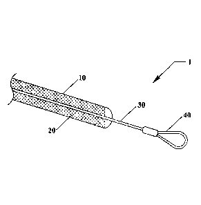
FIG. 1 is a perspective view of a Volume Donating Compressible Filler
(VDCF) device 1 with pulling cord 30 with a partially exposed side. FIG. 2 is
a
cross-sectional view of the VDCF device 1 of FIG. 1. Referring to FIGURES 1-
2, the VDCF device 1 can include a non-conductive durable outer coating 10,
that surrounds a closed cell foam 20, with a pull cord 30 extending
therethrough, and a loop end 40.
FIG. 3 is a perspective view of plural VDCF devices 1 of FIGURES 1-2
adjacent to communication and power conductor cables 50. A plurality of
VDCF devices 1 can be arranged side by side about communication and
power cables 50 within respective sleeves 55. In this application, three VDCF
12
Date Recue/Date Received 2022-12-21
devices 1 can be arranged about three communication and power cables 50
within respective sleeves 55.
FIG. 4 is a front cutaway view of a conduit/duct 60 positioned at the
bottom of a freshly excavated trench 70, before installation of the novel VDCF
devices along with the communication and power cables 50.
FIG. 5 is a side view of the VDCF devices 1 and communication/power
conductor cables 50 from FIG. 3 in the conduit/duct 60 of FIG. 4. In this
application the communication and power cables 50 can have capped ends 54
with pull lines 56 and eyelet ends 58. FIG. 6 is a perspective view of the
VDCF
devices 1 and power and communication cables 50 of FIG. 5 being pulled
through the conduit/duct with pulling eyes 58.
FIG. 7 is a side view of the VDCF devices 1 and communication/power
conductor cables 50 of FIGURES 5-6 being installed in the conduit/duct of
FIG. 4. The VDCF devices 1 and communication and power cables 50 can
initially be positioned on a spool 140 adjacent to an inlet box/vault 150
where
the duct/conduit 60 begins. A mechanical cable puller 130 such as a motor
drum can be located adjacent to an outlet box/vault 160, which can be
attached to one end of a main pull line 110 which passes about pulleys 120 to
a pulling head 100 which can be attached to eyelet ends 58 of
communication/power cables 50 and loop ends 40 on pull cords of the VDCF
devices 1.
A method of installing the novel VDCF devices 1 along with the power
and communication cables 50 will now be described in reference to FIGURES
1-7.
13
Date Recue/Date Received 2022-12-21
CA 02938486 2016-08-10
Installation Method Steps:
The following installation method steps allow for installation of below grade
conduits/ducts and subsequent installation of conductors within that conduit.
1. Excavate the trench for the conduit/duct.
2. Assemble sections of the conduit/duct.
3. Place the assembled conduit/duct into the trench.
4. Backfill and compact the conduit/duct with excavated or select
materials as appropriate for local conditions.
5. Pig the conduit to remove debris.
6. Blow in a small pull line.
7. Use the small pull line to pull in a full tension pull rope.
8. Place conductor spools on rollers, one per conductor and one for each
compressible volume donator run.
9. Connect all conductors and each compressible volume donator run to
the pulling head or full tension pull rope.
10.While slowly pulling the full tension rope, bundle the conductors and
compressible volume donating material into an assembly and feed the
complete assembly into the throat of the conduit.
11. Conductor lubricants may be used to reduce pulling tension as is
typical or as required.
12. Continue pulling the assembly into the conduit/duct until the full tension
pull rope and adequate conductors and volume donating material is
14
CA 02938486 2016-08-10
clear of the installed conduit end with adequate lengths as required for
connections.
13. Disconnect the full tension pull rope.
14. Terminate the conductors.
FIG. 8 is a cross-sectional view of the installed VDCF devices 1 and
communication/power conductor cables 50 of FIGURES 5-7 installed in the
conduit/duct 60 with thawed compacted fill 75T.
FIG. 9 is another cross-sectional view of the installed VDCF devices 1 and
communication/power conductor cables 50 installed in the conduit/duct 60 of
FIG. 8 with frozen compacted fill 75F and Frozen Water (FW) inside of the
conduit/duct 60 frozen to expand against and compress sides of the VDCF
devices 1. As.shown the VDCF devices 1 can compress, for example, in an
elliptical shape, to take up a percentage of the volume being displaced by the
expanding frozen water.
An exemplary conduit freezing filler calculation is shown below.
Table 1 shows the inside diameter (ID) of several common sizes of
Schedule 40 rigid metal conduit. For the following example a 3 inch rigid
metal
conduit with an ID of 3.068 inches is selected to hold the three 15 kilovolt
1/0
awg copper conductor concentric neutral cables that each have an outside
diameter (OD) of 1.125 inches. The 5/8 inch VDCF was selected from Table 2
with an integral 1/4" pulling-line (p-line). The area of the 1/4 inch p-line
is subtracted
from the area Of the 5/8 inch compressive material to yield an effective
compressive area for each VDCF of 0.2278 square inches.
CA 02938486 2016-08-10
The area of the conduit (ID =3.068") is computed to be 7.3927 square
inches. Subtracting the three cables (OD =1.125") having a total area of
2.9821
square inches and the three VDCF (ID -0.594") that have a total area of 0.8314
square inches, yields a remaining potential water area of 3.5792 square
inches.
Using the 9.399% expansion coefficient of water on the 3.5792 square
inch potential water area yields a required water expansion area of 0.3364
square inches. Using the compressive area for 5/8" VDCF with a 1/4" p-line
from
Table 2 of 0.2278 square inches, each, yields a total compressive area of the
three VDCF of 0.6834 square inches. Dividing the water expansion area of
0.3364 square. inches by the total VDCF compressive area of 0.6834 square
inches yields 0.4922 or 49.22% compression, which is within the recommended
50% compression for this material and will allow for rebound when the ice
melts.
Conduit(Schedule 40 Area
ID" 3.068 7.3927 sq. in.
Conductors
Total OD"
3 1.125 2.9821 sq. in.
Filler
Total OD" Compress Area
3 0.594" 0.8314 sq. in.
16
CA 02938486 2016-08-10
Total Water Area 3.5792 sq. in.
Ice Expansion Percentage 9.399%
Ice Expansion Area 0.3364 sq. in.
VDCF Compression Area
3 x 0.2278 sq.in. 0.6834 sq. in.
Percent Compression of Filler 49.22%
(50% maximum)
Table 1- Inside diameter (ID) of several common sizes of Schedule 40 rigid
metal
conduit.
Table Size ID Sched. 40
1/2 0.622
34 0.824
1 1.049
1 & 1/4 1.380
1 & 1/2 1.610
2 2.067
2 & 1/2 2.469
3 3.068
3 & 1/2 3.548
4 4.026
5 5.047
6 6.065
17
CA 02938486 2016-08-10
Table 1 shows the different inside diameters of a range of rigid metal
conduits.
Generally, the larger the cables or an increased number of cables will require
a
larger conduit. The maximum conduit fill is limited as a result of several
factors in
the electrical codes.
Table 2 Effective Compression Areas (square inches) for 5/8 filler with two
different sized pull-lines (P-line)
Filler with P-line core Compressible
Filler OD P-line OD Area
5/8 0.594" 0.25" 0.2278 sq. in.
5/8 = 0.594" 0.375" 0.1664 sq. in.
Table 2 shows the reduction on compression area as the size of the p-line
is increased. The size of the p-line should be sized as small as possible to
maximize the compressible area of the VDCF.
The VDCF can be made from a material that is non-conductive, non-water
absorbing, compressible and abrasion resistant. The size may vary from large
to
small depending on the application. As a practical matter the number of VDCF
should be limited for ease of installation and the compression should be
limited to
a level that will allow for ready rebound to the original size upon thawing of
the
surrounding ice. For the example, three VDCF were installed with a compression
of less than 50%. The core material can be non-water absorbing and abrasion
18 =
CA 02938486 2016-08-10
resistant on its own and negate the need to the outer coating or could be
strong
enough to negate the need for a pull rope.
The number of VDCF sizes may be held to a minimum to help control
inventory costs, but can have a diameter that will typically range from
approximately 1/8" to approximately 11/4".
Alternative Materials for the core filler are described below:
COMPRESSIBLE CORE FILLER-
First Tier Closed Cell Foam:
NOMACO HBR Closed-cell foam Backer Rod
DESCRIPTION
Round, flexible, continuous lengths of extruded, closed-cell
Polyethylene foam backer rod for use as a backing material
for elastomeric and other cold applied sealants.
Sizes 1/8", 1/4", 3/8", 1/2", 5/8", 3/4" 7/8", 1", 1 1/4"
CERAMAR
DESCRIPTION
CERAMAR is a flexible foam expansion joint filler composed
of a unique synthetic foam of isomeric polymers in a very
small, closed-cell structure. Gray in color, CERAMAR is a
lightweight, flexible, highly resilient material offering recovery
qualities of over 99%. The compact, closed-cell structure will
absorb almost no water.
https://www.wrmeadows.com/ceramar-flexible-foam-
=
expansion-joint/
Neoprene
DESCRIPTION
Neoprene rubber foam, renowned for its ability to be soft and
flexible, but still durable and reliable. It is highly resistant to
many hazards, including ozone, sunlight, and oxidation, as
well as many chemicals and water.
=
19
CA 02938486 2016-08-10
Second Tier Materials
Latex Rubber Based Tubing (Surgical Tubing)
Latex rubber tubing has many of the required properties, but
is limited in its effectiveness as there is only one cell, the
void in the inside of the tubing. A single breach of the tubing
will compromise the entire installation.
EXAMPLES OF THE OUTER COATING ARE DESCRIBED BELOW-
Neoprene
DESCRIPTION
Neoprene rubber foam, renowned for its ability to be soft and
flexible, but still durable and reliable. It is highly resistant to
many hazards, including ozone, sunlight, and oxidation, as
well as many chemicals and water.
Polyethylene
Potential coatings include PTFE, PFA, TFE, Tefzel/ETFE
and FEP, Krytox, Vydax, Silverstone, Xylan, Dykor, Castall,
Halar, Emralon, Kynar, Electrofilm, Everlube, dry film
lubricant and dielectric. Finishes include non-stick, non-
wetting, heat resistant, chemical resistant and cryogenically
stable to low temperatures. Coatings applied to a wide
variety of substrates including metals, elastomers,
composites, rubber, ceramics and glass.
EXAMPLES OF THE PULL CORD ARE DESCRIBED BELOW-
NYLON ROPE
Shock absorbent. Recommended for securing boats, cargo and furniture.
= Strong, abrasion resistant.
= Flexible, easy to knot. Won't rot or mildew.
= Solid Braided ¨ Smooth. Works well in pulleys.
= Twisted ¨ General, all-purpose rope. Easy to grip and splice.
= Double Braided ¨ A rope within a rope. Extra strong for towing and
anchor lines.
=
CA 02938486 2016-08-10
Kevlar
Kevlar is the same material used in bullet proof vests, and Kevlar
line is currently specified for the Navy SEALS survival kits.
The 2001b Kevlar line is made of 3 twisted Kevlar strands.
When broken down, 60' of Kevlar 200 line produces 180 of Kevlar
thread, with a break strength of approximately 60Ibs. This Kevlar
thread can be used for sewing, fishing, or shelter building.
Kevlar line is also extremely heat resistant, allowing it to be used as
a friction saw for cutting through flex cuff handcuffs and PVC pipe.
Spyderwire0
Dyneema PE Microfiber construction is strong, smooth and
round
Fluoropolymer Treated microfibers - shoots through guides
like a bullet!
=
SpiderWire Stealth is made from Dyneema , The
World's Strongest Fiber! Available in Moss Green for low-
visibility underwater, Hi-Vis Yellow for visibility above water,
or NEW Translucent for high visibility above water, and less
visibility below. Constructed to provide ultimate strength with
the thinnest diameter for smooth and quiet performance. The
no stretch properties of Dyneema PE
21
CA 02938486 2016-08-10
The term "approximately" can be +/- 10% of the amount referenced.
Additionally, preferred amounts and ranges can include the amounts and ranges
referenced without the prefix of being approximately.
While the invention has been described, disclosed, illustrated and shown
in various terms of certain embodiments or modifications which it has presumed
in practice, the scope of the invention is not intended to be, nor should it
be
deemed to be, limited thereby and such other modifications or embodiments as
may be suggested by the teachings herein are particularly reserved especially
as
they fall within the breadth and scope of the claims here appended.
22