Note : Les descriptions sont présentées dans la langue officielle dans laquelle elles ont été soumises.
CA 02939867 2016-08-16
WO 2015/152981 PCT/US2015/011634
POSITIONING SYSTEM FOR AN ELECTROMECHANICAL ACTUATOR
BACKGROUND
Actuators are used in various mechanical devices to control the features
and moving parts of these devices. Specifically, an actuator is a motor that
is used to
control a system, mechanism, device, structure, or the like. Actuators can be
powered
by various energy sources and can convert a chosen energy source into motion.
For instance, actuators are used in computer disk drives to control the
location of the read/write head by which data is stored on and read from the
disk. In
addition, actuators are used in robots, i.e., in automated factories to
assemble products.
Actuators also operate brakes on vehicles, open and close doors, raise and
lower
railroad gates, and perform numerous other tasks of everyday life.
Accordingly,
actuators have wide ranging uses.
In the field of aeronautics, actuators are used to control a myriad of control
surfaces that allow aircraft to fly. For instance, each of the flaps,
spoilers, and ailerons
located in each wing, require an actuator. In addition, actuators in the tail
control the
rudder and elevators of an aircraft. Furthermore, actuators in the fuselage
open and
close the doors that cover the landing gear bays. Actuators are also used to
raise and
lower the landing gear of an aircraft. Moreover, actuators on each engine
control thrust
reversers by which a plane is decelerated.
Commonly used actuators fall into two general categories: hydraulic and
electric, with the difference between the two categories being the motive
force by which
movement or control is accomplished. Hydraulic actuators require a
pressurized,
incompressible working fluid, usually oil. Electric actuators use an electric
motor, the
shaft rotation of which is used to generate a linear displacement using some
sort of
transmission.
Although hydraulic actuators have been widely used in airplanes, a
problem with hydraulic actuators is the plumbing required to distribute and
control the
pressurized working fluid. In an airplane, a pump that generates high-pressure
working
fluid and the plumbing required to route the working fluid add weight and
increase
design complexity because the hydraulic lines must be carefully routed. In
addition,
possible failure modes in hydraulic systems include pressure failures, leaks,
and
electrical failures to servo valves that are used to position control
surfaces. However,
1
one inherent feature of hydraulic systems is that hydraulic flight control
systems can
use damping forces to maintain stability after a failure has been detected.
Electric actuators overcome many of the disadvantages of hydraulic
systems. In particular, electric actuators, which are powered and controlled
by electric
.. energy, require only wires to Operate and control. However, electric
actuators can also
fail during airplane operation.
For instance, windings of electrical motors are
susceptible to damage from heat and water. In addition, bearings on motor
shafts wear
out. The transmission between the motor and the load, which is inherently more
complex than the piston and cylinder used in a hydraulic actuator, is also
susceptible to
failure. In both electrical and hydraulic systems a mechanical failure of an
actuator, e.g.
gear or bearing failure, etc., can result in a loss of mechanical function of
the actuator.
In addition, electrical systems can fail. One type of electrical failure
occurs when there
is a failure of the command loop that sends communications to an actuator.
Another
type of electrical failure occurs when a power loop within the actuator fails,
such as a
high power loop to a motor.
As electronic actuator systems are increasingly used in aircraft designs,
new approaches are needed to address possible failure modes of these systems.
Fault-tolerance, i.e., the ability to sustain one or more component failures
or faults yet
keep working, is needed in these systems. Because electric flight control
systems do
not have hydraulic fluid available for damping, there is a need for
alternative fail safe
systems that can be used in the event of a failure.
SUMMARY
Provided are various examples of a shaft positioning system that can be
used as a secondary fail-safe system for an electromechanical actuator when a
primary
system fails. According to various examples, the positioning system includes a
shaft
coupled to an electromechanical actuator. The shaft moves along 8 linear axis
and the
electromechanical actuator is free to translate during normal operation.
An
electromagnetic coil is positioned around at least a portion of the shaft. The
electromagnetic coil produces a magnetic field when electrical current is
applied. A
metal housing surrounds at least a portion of the electromagnetic coil. The
shaft is
placed in a predetermined position when the metal housing is in' contact with
a first
2
CA 2939867 2019-12-13
magnet and translational motion of the electromechanical actuator is
restricted when
the shaft is placed in the predetermined position.
According to various examples, a mechanism includes a flight control
computer system, a translating shaft having an axis, an electromechanical
actuator that
moves the translating shaft along the axis, and a shaft positioning system.
The
electromechanical actuator is communicatively coupled to the flight control
computer.
The shaft positioning system includes a shaft coupled to the electromechanical
actuator. The shaft moves along a linear axis and the electromechanical
actuator is
free to translate during normal operation. The shaft positioning system also
includes an
electromagnetic coil positioned around at least a portion of the shaft. The
electromagnetic coil produces a magnetic field when electrical current is
applied. A
metal housing surrounds the electromagnetic coil. In addition, the shaft
positioning
system includes a first magnet. The shaft is placed in a predetermined
position when
the metal housing is in contact with the first magnet and translational motion
of the
translating shaft and the electromechanical actuator is restricted when the
shaft is
placed in the predetermined position.
According to various examples, a method includes driving a shaft using
an electromechanical actuator, wherein the electromechanical actuator is free
to
translate during normal operation; applying an electrical current to an
electromagnetic
coil to produce a change in magnetic field, wherein the electromagnetic coil
is
positioned around at least a portion of the shaft and is at least partially
surrounded by a
metal housing, wherein the shaft moves in response to the change in magnetic
field;
and restricting a translational motion of the electromechanical actuator when
the shaft
is placed in a predetermined position, wherein the shaft is placed in the
predetermined
position when the metal housing is in contact with a first magnet.
According to various examples, a shaft positioning system comprises: a
shaft coupled to an electromechanical actuator, wherein the shaft is
configured to
move along a linear axis, and wherein the electromechanical actuator is free
to
translate during normal operation; an electromagnetic coil positioned around
at least a
portion of the shaft, wherein the electromagnetic coil is configured to
produce a
magnetic field when electrical current is applied; a metal housing surrounding
at least a
portion of the electromagnetic coil; a first magnet, wherein the shaft is
placed in a
predetermined position when the metal housing is in contact with the first
magnet, and
3
CA 2939867 2019-12-13
wherein translational motion of the electromechanical actuator is restricted
when the
shaft is placed in the predetermined position; a driving cam coupled to the
shaft; and a
locking cam, wherein the driving cam and the locking cam are configured to
engage
when the driving cam is in a protracted position thereby locking the shaft in
the
predetermined position and preventing further rotation of the shaft relative
to the metal
housing while the driving cam and the locking cam remain engaged, and wherein
the
driving cam and locking cam are configured to disengage when the driving cam
is in a
retracted position.
According to various examples, an apparatus comprises: a flight control
computer system; a translating shaft having an axis; an electromechanical
actuator that
moves the translating shaft along the axis, wherein the electromechanical
actuator is
communicatively coupled to the flight control computer; and a shaft
positioning system
comprising: a shaft coupled to the electromechanical actuator, wherein the
shaft is
moveable along a linear axis, and wherein the electromechanical actuator is
free to
translate during normal operation; an electromagnetic coil positioned around
at least a
portion of the shaft, wherein the electromagnetic coil produces a magnetic
field when
electrical current is applied; a metal housing surrounding at least a portion
of the
electromagnetic coil; a first magnet, wherein the shaft is placed in a
predetermined
position when the metal housing is in contact with the first magnet, and
wherein
translational motion of the translating shaft and the electromechanical
actuator is
restricted when the shaft is placed in the predetermined position; a driving
cam coupled
to the shaft; and a locking cam, wherein the driving cam and the locking cam
are
conditioned to engage when the driving cam is in a protracted position thereby
locking
the shaft in the predetermined position and preventing further rotation of the
shaft
relative to the metal housing while the driving cam and the locking cam remain
engaged, and wherein the driving cam and locking cam are conditioned to
disengage
when the driving cam is in a retracted position.
According to various examples, a method comprises: driving a shaft
using an electromechanical actuator, wherein the electromechanical actuator is
free to
translate during normal operation; applying an electrical current to an
electromagnetic
coil to produce a change in magnetic field, wherein the electromagnetic coil
is
positioned around at least a portion of the shaft and is at least partially
surrounded by a
metal housing, and wherein the shaft moves in response to the change in the
magnetic
4
CA 2939867 2019-12-13
field; and restricting a translational motion of the electromechanical
actuator when the
shaft is placed in a predetermined position, wherein the shaft is placed in
the
predetermined position when the metal housing is in contact with a first
magnet,
wherein a driving cam and a locking cam engage when the driving cam is in a
protracted position thereby locking the shaft coupled to the driving cam in
the
predetermined position and preventing further rotation of the shaft relative
to the metal
housing while the driving cam and the locking cam remain engaged, and wherein
the
driving cam and locking cam are disengaged when the driving cam is in a
retracted
position.
According to various examples, a mechanism comprises: a linear
electromechanical: actuator comprising an electromagnetic coil; a shaft
positioning
system coupled to the linear electromechanical actuator; a shaft coupled to
the linear
electromechanical actuator which moves along a linear axis, the
electromagnetic coil
being positioned around at least a portion of the shaft, wherein the
electromagnetic coil
produces a magnetic field when electrical current is applied; a metal housing
surrounding at least a portion of the electromagnetic coil; a first magnet,
wherein the
shaft is placed in a predetermined position when the metal housing is in
contact with
the first magnet, wherein translational motion of the electromechanical
actuator is
restricted when the shaft is placed in the predetermined position; a driving
cam coupled
to the shaft; a locking cam, wherein the driving cam and the locking cam
engage when
the driving cam is in a protracted position thereby selectively locking the
shaft in the
predetermined position and preventing further axial movement and rotation
movement
of the shaft relative to the metal housing while the driving cam and the
locking cam
remain engaged, and wherein the driving cam and locking cam are disengaged
when
the driving cam is in a retracted position; and at least one of a second
magnet member
which has a weaker magnetic field than the first magnet and a spring coupled
to the
shaft for moving the driving cam to the protracted position, wherein the
spring holds the
shaft in the retracted position when the electrical current is applied to the
electromagnetic coil, and wherein the electromagnetic coil repels the first
magnet when
the electrical current is applied.
5
Date Recue/Date Received 2020-09-11
According to various examples, a method comprises: driving a shaft using
a linear electromechanical actuator which moves along a linear axis, in which
the linear
electromechanical actuator comprises an electromagnetic coil, and a shaft
positioning
system comprising a shaft coupled to the linear electromechanical actuator;
applying an
electrical current to an electromagnetic coil to produce a change in magnetic
field, the
electromagnetic coil being positioned around at least a portion of the shaft
and being at
least partially surrounded by a metal housing, wherein the shaft moves in
response to
the change in the magnetic field; and restricting a translational motion of
the
electromechanical actuator when the shaft is placed in a predetermined
position,
wherein the shaft is placed in the predetermined position when the metal
housing is in
contact with a first magnet, wherein a driving cam and a locking cam engage
when the
driving cam is in a protracted position thereby selectively locking the shaft
in the
predetermined position and preventing further axial movement and rotation of
the shaft
relative to the metal housing while the driving cam and the locking cam remain
engaged, wherein the driving cam and locking cam are disengaged when the
driving
cam is in a retracted position, and wherein moving the driving cam to the
protracted
position comprises use of at least one of a second magnet member which has a
weaker
magnetic field than the first magnet, and a spring coupled to the shaft for
moving the
driving cam to the protracted position, wherein the spring holds the shaft on
the
retracted position when the electrical current is applied to the
electromagnetic coil, and
wherein the electromagnetic coil repels the first magnet when the electrical
current is
applied.
6
Date Recue/Date Received 2020-09-11
These and other embodiments are described further below with reference
to the figures.
BRIEF DESCRIPTION OF THE DRAWINGS
FIGs. 1A-1B are diagrammatic representations of a positioning system
using electromagnetic and spring forces for an electromechanical linear
actuator, in
accordance with some embodiments.
FIGs. 2A-2B are diagrammatic representations of an alternative
positioning system using electromagnetic and spring forces for an
electromechanical
linear actuator, in accordance with some embodiments.
FIGs. 3A-3B are diagrammatic representations of a positioning system
using electromagnetic and magnetic forces for an electromechanical linear
actuator, in
accordance with some embodiments.
FIGs. 4A-4B are diagrammatic representations of a positioning system
used with an electromechanical linear actuator, in accordance with some
embodiments.
FIGs. 5A-5B are diagrammatic representations of a positioning system
using electromagnetic and spring forces for an electromechanical rotary
actuator, in
accordance with some embodiments.
FIGs. 6A-6B are diagrammatic representations of a positioning system
using electromagnetic and magnetic forces for an electromechanical rotary
actuator, in
accordance with some embodiments.
FIGs. 7A-7B are diagrammatic representations of a positioning system
used with an electromechanical rotary actuator, in accordance with some
embodiments.
FIG. 8 is a diagrammatic representation of an aircraft flight control system,
.. in accordance with some embodiments.
6a
Date Recue/Date Received 2020-09-11
CA 02939867 2016-08-16
WO 2015/152981 PCMJS2015/011634
FIG. 9A is a process flowchart reflecting key operations in the life cycle of
an aircraft from early stages of manufacturing to entering service, in
accordance with
some embodiments.
FIG. 9B is a block diagram illustrating various key components of an
aircraft, in accordance with some embodiments.
DETAILED DESCRIPTION OF EXAMPLE EMBODIMENTS
In the following description, numerous specific details are set forth in order
to provide a thorough understanding of the presented concepts. The presented
concepts may be practiced without some or all of these specific details. In
other
instances, well known process operations have not been described in detail so
as to not
unnecessarily obscure the described concepts. While some concepts will be
described
in conjunction with the specific embodiments, it will be understood that these
embodiments are not intended to be limiting.
Introduction
As electromechanical actuator systems are increasingly used in aircraft
designs, new approaches are needed to address possible failure modes of these
systems. Fault-tolerance, i.e., the ability to sustain one or more component
failures or
faults yet keep working, is needed in these systems. Because electric flight
control
systems do not have hydraulic fluid available for damping, there is a need for
alternative
fail safe systems that can be used in the event of a failure.
A primary flight control system requires the control surfaces to be stable
even after failures occur in the actuation systems. In the case of a primary
flight control
.. system failure, the control surface must continue to be stable by either
maintaining
sufficient damping or locking in place. If the control surface is not damped
or locked,
the surface can become unstable, resulting in failure of the wing to function
appropriately.
Various mechanisms are presented that are designed to stabilize primary
flight control surfaces in the event of a failure to the primary flight
control actuation
system. In particular, various examples provide a secondary fail-safe system
that
positions and holds the flight control surface should the primary drive system
fail,
thereby providing stability of the flight control surface. Specifically, the
positioning
7
CA 02939867 2016-08-16
WO 2015/152981 PCMJS2015/011634
system includes an electromagnetic coil used to position and secure an
electromechanical actuator, according to various examples. In case of a power
failure,
the shutdown of electric power, or a mechanical failure, the positioning
system returns
the electromechanical actuator to a predetermined position, such as a known or
neutral
position. In addition, according to various embodiments, the positioning
system can
automatically reset itself into an operating position after being placed into
a
predetermined position.
Although various examples described relate to the use of a positioning
system for electromechanical actuators with aircraft designs, the positioning
system can
be used with various mechanical devices and vehicles. For instance, the
positioning
system can be used in commercial airplanes, military airplanes, rotorcraft,
launch
vehicles, spacecraft/satellites, and the like. Furthermore, the positioning
system can be
used in vehicle guidance control systems. In addition, the positioning system
can be
used in various devices such as, but not limited to, robots, land vehicles,
rail vehicles,
gates, doors, and the like.
System Examples
Various mechanisms are presented that provide an electromechanical
shaft positioning system that can be used as a secondary fail-safe system when
a
primary system fails. With reference to FIGs. 1A-1B, shown are diagrammatic
representations of a shaft positioning system for an electromechanical linear
actuator, in
accordance with some embodiments. In particular, the positioning system in
FIG. 1A is
shown in a retracted position and the positioning system in FIG. 1B is shown
in a
protracted position. The shaft positioning system 100 combines the use of
electromagnetic and mechanical spring forces to operate a shaft 103 that can
be used
to move an electromechanical actuator (not shown) to a predetermined position,
such
as a neutral or centered position. Application of the shaft positioning system
is
described in more detail with regard to FIGs. 4A-4B and 8.
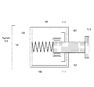
In the example shown in FIG. 1A, positioning system 100 includes a
housing 101, shaft 103, spring 105, magnet 107, metal housing 109, and
electromagnetic coil 111. Spring 105 can be any type of mechanical spring,
such as a
set of Belleville washers, bellows springs, etc. When an electrical current is
supplied to
electromagnetic coil 111, the electromagnetic field produced causes the
8
CA 02939867 2016-08-16
WO 2015/152981 PCT/1JS2015/011634
electromagnetic coil 111 to repel magnet 107. As electromagnetic coil 111
repels
magnet 107, shaft 103 retracts and compresses mechanical spring 105. In this
configuration, spring 105 is counterbalanced by the operation of
electromagnetic coil
111. As shown, the shaft remains in a retracted position as long as an
electrical current
is supplied to electromagnetic coil 111.
Upon a normal power shutdown, power failure, or mechanical failure, the
spring 105 expands and pushes the shaft 103 towards magnet 107, as shown in
FIG.
1B. The metal housing 109 is attracted to magnet 107 and attaches to magnet
107,
thereby moving and stabilizing shaft 103 into a predetermined position.
In the present embodiment, positioning system 100 combines the use of
electromagnetic and mechanical spring forces to operate shaft 103 to adjust an
electromechanical actuator to a predetermined position. For instance, shaft
103 can be
used in case of a power failure to return the electromechanical actuator of a
control
surface or rotor blade to a safe position, or to return a control surface or
rotor blade to a
known position with accuracy during flight. In addition, positioning system
100 can drive
an electromechanical actuator to a predetermined position and magnetically
lock the
electromechanical actuator and shaft 103 into a particular position. As
described in
more detail with regard to FIGs. 4A-4B, the electromechanical actuator is
stabilized
when moved and locked into the predetermined position, such that movement of
the
electromechanical actuator is reduced and resisted.
In the present embodiment, positioning system 100 can be reset to a
retracted position once a protracted position is no longer needed. In
particular, an
electrical current can be provided to electromagnetic coil 111 such that it
repels magnet
107. Attraction between metal housing 109 can be broken and the
electromagnetic coil
111 can again repel magnet 107, such as to cause shaft 103 to compress spring
105.
In this manner, the position of shaft 103 can be controlled and reset
automatically
depending on the amount and direction of the electrical current supplied to
the
electromagnetic coil 111.
With reference to FIGs. 2A-2B, shown is an alternate embodiment of a
positioning system for an electromechanical linear actuator. In particular,
FIG. 2A
depicts the positioning system in a retracted position and FIG. 2B depicts the
positioning system in a protracted position. The shaft positioning system 200
combines
the use of electromagnetic and mechanical spring forces to operate a shaft 203
that can
9
CA 02939867 2016-08-16
WO 2015/152981 PCMJS2015/011634
be used to move an electromechanical actuator (not shown) to a predetermined
position, such as a neutral or centered position. Application of the shaft
positioning
system is described in more detail with regard to FIGs. 4A-4B and 8.
In the present embodiment, positioning system 200 includes a housing
201, shaft 203, spring 205, magnet 207, metal housing 209, electromagnetic
coil 211,
and spring housing 213. Spring 205 can be any type of mechanical spring, such
as a
set of Belleville washers, bellows springs, etc. As shown in FIG. 2A, spring
205 keeps
shaft 203 in a retracted position. Specifically, the spring is allowed to
fully extend and
keep spring housing 213 away from magnet 207. When an electrical current is
applied
to electromagnetic coil 211 in one direction, spring housing 213 is attracted
to magnet
207 due to the magnetic forces induced by the current.
As shown in FIG. 2B, spring housing 213 then attaches itself to magnet
207, and shaft 203 is pushed into a protracted position and held in place by
the
attractive force between spring housing 213 and magnet 207. Once spring
housing 213
is attached to magnet 207, the electrical current can be turned off. Shaft 203
then
remains in this protracted position due to the attractive force between the
magnet and
the spring housing without any electrical current applied.
According to various embodiments, positioning system 200 can be reset to
a retracted position once a protracted position is no longer needed.
Specifically, to
return the shaft to a retracted position, an electrical current can be pulsed
through the
electromagnetic coil 211 in the opposite direction from when the electrical
current was
applied to attract magnet 207 to spring housing 213. By pulsing the electrical
current
through electromagnetic coil 211 in this manner, spring housing 213 can detach
from
magnet 207 and begin to repel magnet 207. Once spring 205 is allowed to
expand,
thereby keeping spring housing 213 away from magnet 207, no more electrical
current
needs to be applied to the electromagnetic coil 211. In the present
embodiment, if a
power failure, normal power shutdown, or mechanical failure occurs, a
secondary power
source would be needed to return shaft 203 to a protracted position.
With reference to FIGs. 3A-3B, shown is another embodiment of a
positioning system for an electromechanical linear actuator. In particular,
FIG. 3A
depicts the positioning system in a retracted position and FIG. 3B depicts the
positioning system in a protracted position. The shaft positioning system 300
combines
the use of electromagnetic and magnetic forces to operate a shaft 303 that can
be used
CA 02939867 2016-08-16
WO 2015/152981 PCMJS2015/011634
to move an electromechanical actuator (not shown) to a predetermined position,
such
as a neutral or centered position. Application of the shaft positioning system
is
described in more detail with regard to FIGs. 4A-4B and 8.
In the present embodiment, positioning system 300 includes a housing
301, shaft 303, weak magnet 305, strong magnet 307, metal housing 309, and
electromagnetic coil 311. As shown in FIGs. 3A-3B, positioning system 300 uses
two
sets of magnets to move shaft 303 between a retracted and a protracted
position. In
order to keep shaft 303 in the retracted position depicted in FIG. 3A,
electrical current
must continuously flow through electromagnetic coil 311 to attract it to weak
magnet
305 and repel it from strong magnet 307. Although electrical current must be
continuously applied to electromagnetic coil 311 to keep shaft 303 in this
position, metal
housing 309 attaches to weak magnet 305 such that the shaft 303 is stabilized
in this
position and is limited to little or negligible movement.
In order to move shaft 303 to the protracted position, the electrical current
must be reversed momentarily through electromagnetic coil 311 so that metal
housing
309 will disconnect from weak magnet 305. Once the metal housing 309 is
disconnected from weak magnet 305, it will attract to strong magnet 307
because strong
magnet 307 will have a stronger magnetic pull on metal housing 309. Once metal
housing 309 has attached to strong magnet 307, the electrical current can then
be
turned off because strong magnet 307 will keep shaft 303 in place.
In the event of a power failure, mechanical failure, or normal shut down,
electromagnetic coil 311 will no longer be magnetized and the metal housing
309 will be
attracted to the stronger of the weak magnet 305 and strong magnet 307
automatically.
Once the metal housing 309 attaches to strong magnet 307, shaft 303 is secured
in a
protracted position. This protracted position can be used to position and
secure an
electromechanical actuator in some examples. Application of the shaft
positioning
system is described in more detail with regard to FIGs. 4A-4B and 8.
In the present embodiment, positioning system 300 can be reset to a
retracted position once a protracted position is no longer needed. In
particular,
electrical current can be provided to electromagnetic coil 111 such that it
repels strong
magnet 307. Attraction between metal housing 309 and strong magnet 307 can be
broken and electromagnetic coil 311 can again repel strong magnet 307, such as
to
cause shaft 303 to move towards weak magnet 305. Once metal housing 309
reaches
11
CA 02939867 2016-08-16
WO 2015/152981 PCMJS2015/011634
weak magnet 305, it attaches to weak magnet 305 and stays in place while the
electrical current is applied. In this manner, the position of shaft 303 can
be controlled
and reset automatically depending on the amount and direction of electrical
current
supplied to the electromagnetic coil 311.
With reference to FIGs. 4A-4B, shown are diagrammatic representations
of positioning systems used with an electromechanical linear actuator, in
accordance
with some embodiments. As shown, four positioning systems 401 are located
within
housing 400. Translating shaft 403 passes through housing 400 and includes
flange
405. Flange 405 can project out from two sides of translating shaft 403 in
some
examples as shown, and can form a ring or other shape around translating shaft
in
other examples. Translating shaft 403 can reciprocate or translate 407 in the
direction
of its longitudinal axis between the retracted shafts of the positioning
systems 401. This
translating shaft 403 can be a part of another mechanical system or actuator
that
provides control of translation 407 during normal operation.
Depending on the
application, translation can be in the range of about 1/2 inch in some
examples, in the
range of 5 to 10 inches in other examples, or any other distance depending on
how the
translating shaft 403 is used within a mechanical device or actuator.
In the present embodiment, positioning systems 401 serve as a secondary
fail-safe system when a primary system fails. In particular, motion of
translating shaft
403 can be controlled by an actuator (not shown) that is part of the primary
system.
During normal actuator operation, the positioning system shafts are held in a
retract
position, as shown. Examples of positioning systems that can be held in
retracted and
protracted positions are described above with regard to FIGs. 1A-1B, 2A-2B,
and 3A-
3B. In the present embodiment, positioning systems like the ones described in
conjunction with FIGs. 3A-3B are shown. However, any of the positioning
systems
previously described can be used to secure translating shaft 403 in a similar
manner.
With the shafts of positioning systems 401 retracted, the translating shaft
403 is free to move through a normal stroke without interference from the
positioning
system shafts.
However, during a power failure, mechanical failure, or normal
shutdown, the positioning system shafts move into a protracted position and
push up
against the translating shaft flange 405. In some examples, the positioning
system
shafts drive the translating shaft 403 to a predetermined position, such as a
center or
neutral position, and hold this position, as shown in FIG. 4B.
12
CA 02939867 2016-08-16
WO 2015/152981 PCMJS2015/011634
Once the system has completed its task of stabilizing translating shaft
403, and this configuration is no longer needed, the positioning systems 401
can be
returned to a retracted position, as described in more detail above with
regard to FIGs.
1A-1B, 2A-2B, and 3A-3B. The positioning system shafts can be restored to
their
original positions, and positioning systems 401 can be used again alongside
the primary
actuator as a fail-safe system during future operations. As described above,
the
positioning systems 401 can be activated during a failure of a primary
actuator or
system. However, in some examples, the positioning systems can be used at
other
times, such as during flight, to secure an actuator shaft in a predetermined
position. As
explained above, the positioning systems 401 can be moved between retracted
and
protracted positions automatically by providing electrical current to the
systems.
In the example shown in FIG. 4B, translating shaft is 403 held in a center
position as its predetermined position. The positioning system shafts restrict
the
movement of the actuator and returns translating shaft 403 to a predetermined
position.
In some embodiments, the positioning system shafts can be positioned
beforehand to
control where the translating shaft 403 will end up when the positioning
system shafts
are in protracted positions. In other examples, the lengths of the positioning
system
shafts can be adjusted to accommodate a particular predetermined position. In
some
examples, the predetermined position can be a neutral position that achieves
the
optimal aerodynamic system, such as to reduce drag forces, etc. In other
examples, a
different predetermined location may be desirable. In some examples, the
number of
positioning system shafts may vary as appropriate to position the translating
shaft 403,
e.g. one, two, three, four or more positioning system shafts on each side of
the
translating shaft 403, or an unequal number of positioning system shafts on
each side of
translating shaft 403.
With reference to FIGs. 5A-5B, shown are diagrammatic representations
of a shaft positioning system for an electromechanical rotary actuator, in
accordance
with some embodiments. In particular, the positioning system in FIG. 5A is
shown in a
retracted, unlocked position and the positioning system in FIG. 5B is shown in
a
protracted, locked position. The shaft positioning system 500 combines the use
of
electromagnetic and mechanical spring forces to operate a shaft 503, locking
cam 513,
and drive cam 515 with respect to each other such as to move an
electromechanical
actuator (not shown) to a predetermined position, such as a neutral or
centered
13
CA 02939867 2016-08-16
WO 2015/152981 PCMJS2015/011634
position. For instance, shaft 503 may be part of an actuator or can be an
extension of
an actuator. In addition, shaft 503 can be threaded in various examples, and
can
include roller screw or ball screw movement in some examples.
In the present embodiment, positioning system 500 integrates the
electrical and mechanical functions of a spring applied electric clutch and
brake to
generate rotational motion that will allow an electromechanical actuator to be
commanded or mechanically or electrically driven to a locked predetermined
position in
the event of a power shutdown, mechanical failure, or system fault. In one
example, the
positioning system can be used in an aircraft such that once the system
mechanically
locks so as to resist actuator movement of an item such as a rotor blade, the
aircraft
can continue the flight with all flight control authority, while active
control of blade twist is
not available in this locked position.
In the example shown in FIG. 5A, positioning system 500 includes housing
501, shaft 503, spring 505, magnet 507, metal housing 509, electromagnetic
coil 511,
locking cam 513, and driving cam 515. Spring 505 can be any type of mechanical
spring, such as a set of Belleville washers, bellows springs, etc. When an
electrical
current is supplied to electromagnetic coil 511, the electromagnetic field
produced
causes the electromagnetic coil 511 to repel magnet 507. As electromagnetic
coil 511
repels magnet 507, shaft 503 retracts and compresses mechanical spring 505. In
this
configuration, spring 505 is counterbalanced by the operation of
electromagnetic coil
511. As shown, the shaft remains in a retracted position as long as an
electrical current
is supplied to electromagnetic coil 511.
Upon a normal power shutdown, power failure, or mechanical failure, the
spring 505 expands and pushes the shaft 503 (which can move via threads,
roller
screw, ball screw, etc.) and drive cam 515 into a protracted position until
metal housing
509 attaches to magnet 507, as shown in FIG. 5B. When the metal housing 509
attaches to magnet 507, driving cam 515 engages with locking cam 513 and shaft
513
is then stabilized into a predetermined position by the locking mechanism and
the
attachment of the metal housing 509 to magnet 507.
In the present embodiment, positioning system 500 combines the use of
electromagnetic and mechanical spring forces to operate shaft 503 and driving
cam 515
to drive a rotary electromechanical actuator to a predetermined position. For
instance,
positioning system 500 can be used in case of a power failure to return the
rotary
14
CA 02939867 2016-08-16
WO 2015/152981 PCMJS2015/011634
electromechanical actuator of a control surface or rotor blade to a safe
position, or to
return a control surface or rotor blade to a known position with accuracy
during flight. In
addition, positioning system 500 integrates the functions of electromagnets
and
mechanical springs to drive an electromechanical actuator to a predetermined
position
.. and mechanically and magnetically lock shaft 503 into a particular
position. When
locked, shaft 503 resists movement of the rotary electromechanical actuator
once it is
placed into the predetermined position. Once the positioning system 500 is in
the locked
position, electrical power can be removed from the system.
According to various embodiments, positioning system 500 provides an
ability to selectively lock and unlock movement of the shaft 503, and
consequently an
attached actuator, with drive cam 515. In particular, positioning system 500
can be
reset to an unlocked/retracted position once a locked/protracted position is
no longer
needed. In particular, an electrical current can be provided to
electromagnetic coil 511
such that it repels magnet 507. Attraction between metal housing 509 can be
broken
and the electromagnetic coil 511 can again repel magnet 507, such as to cause
drive
cam 515 to move away from locking cam 513 and to cause shaft 503 to compress
spring 505. In this unlocked position, shaft 503 can freely rotate. In this
manner,
movement, positioning, and locking of shaft 503 can be controlled and reset
automatically depending on the amount and direction of the electrical current
supplied to
the electromagnetic coil 511.
With reference to FIGs. 6A-6B, shown are diagrammatic representations
of a shaft positioning system for an electromechanical rotary actuator, in
accordance
with some embodiments. In particular, the positioning system in FIG. 6A is
shown in a
retracted, unlocked position and the positioning system in FIG. 6B is shown in
a
protracted, locked position. The shaft positioning system 600 combines the use
of
electromagnetic and magnetic forces to operate a shaft 603, locking cam 613,
and drive
cam 615 with respect to each other such as to move an electromechanical
actuator (not
shown) to a predetermined position, such as a neutral or centered position.
For
instance, shaft 603 may be part of an actuator or can be an extension of an
actuator. In
addition, shaft 603 can be threaded in various examples, and can include
roller screw or
ball screw movement in some examples.
In the present embodiment, positioning system 600 integrates the
electrical and mechanical functions of a spring applied electric clutch and
brake to
CA 02939867 2016-08-16
WO 2015/152981 PCMJS2015/011634
generate rotational motion that will allow an electromechanical actuator to be
commanded or mechanically or electrically driven to a locked predetermined
position in
the event of a power shutdown, mechanical failure, or system fault. In one
example, the
positioning system can be used in an aircraft such that once the system
mechanically
locks so as to resist actuator movement of an item such as a rotor blade, the
aircraft
can continue the flight with all flight control authority, while active
control of blade twist is
not available in this locked position.
In the example shown in FIG. 6A, positioning system 600 includes a
housing 601, shaft 603, weak magnet 605, strong magnet 607, metal housing 609,
electromagnetic coil 611, locking cam 613, and driving cam 615. As shown in
FIGs. 6A-
6B, positioning system 600 uses two sets of magnets to move shaft 603 between
an
unlocked/retracted and a locked/protracted position. In order to keep shaft
603 in the
retracted position depicted in FIG. 6A, electrical current must continuously
flow through
electromagnetic coil 611 to attract it to weak magnet 605 and repel it from
strong
magnet 607. Although electrical current must be continuously applied to
electromagnetic coil 611 to keep shaft 603 in this position, metal housing 609
attaches
to weak magnet 605 such that the shaft 603 and driving cam 615 are stabilized
in this
position. In some embodiments, when the shaft 603 is in this position, the
actuator
attached to the positioning system 600 has free rotation and can move without
interference from the positioning system 600.
In order to move shaft 603 and drive cam 515 to a protracted position, the
electrical current must be reversed momentarily through electromagnetic coil
611 so
that metal housing 609 will disconnect from weak magnet 605. Once the metal
housing
609 is disconnected from weak magnet 605, it will attract to strong magnet 607
because
strong magnet 607 will have a stronger magnetic pull on metal housing 609.
Once
metal housing 609 has attached to strong magnet 607, the electrical current
can then be
turned off because strong magnet 607 will keep shaft 603 in place.
In the event of a power failure, mechanical failure, or normal shut down,
electromagnetic coil 611 will no longer be magnetized and the metal housing
609 will be
attracted to the stronger of the weak magnet 605 and strong magnet 607
automatically.
Once the metal housing 609 attaches to strong magnet 607, shaft 603 is secured
in a
protracted position with metal housing 609 attached to magnet 607, as shown in
FIG.
6B. When the metal housing attaches to magnet 607, driving cam 615 engages
with
16
CA 02939867 2016-08-16
WO 2015/152981 PCT/1JS2015/011634
locking cam 613 and shaft 603 is then stabilized into a predetermined position
by the
locking mechanism and the attachment of the metal housing 609 to magnet 607.
In the present embodiment, positioning system 600 combines the use of
electromagnetic and magnetic forces to operate shaft 603 and driving cam 615
to drive
a rotary electromechanical actuator to a predetermined position. For
instance,
positioning system 600 can be used in case of a power failure to return a
rotary
electromechanical actuator of a control surface or rotor blade to a safe
position, or to
return a control surface or rotor blade to a known position with accuracy
during flight. In
addition, positioning system 600 integrates the functions of electromagnets
and
magnets to drive an electromechanical actuator to a predetermined position and
mechanically and magnetically lock shaft 603 into a particular position. When
locked,
shaft 603 resists movement of the rotary electromechanical actuator once it is
placed
into the predetermined position. Once the positioning system 600 is in the
locked
position, electrical power can be removed from the system.
According to various embodiments, positioning system 600 provides an
ability to selectively lock and unlock movement of the shaft 603, and
consequently an
attached actuator, with drive cam 615. In particular, positioning system 600
can be
reset to an unlocked/retracted position once a locked/protracted position is
no longer
needed. In particular, electrical current can be provided to electromagnetic
coil 611
such that it repels strong magnet 607. Attraction between metal housing 609
and
strong magnet 607 can be broken and electromagnetic coil 611 can again repel
strong
magnet 607, such as to cause shaft 603 to move towards weak magnet 605. Once
metal housing 609 reaches weak magnet 605, it attaches to weak magnet 605 and
stays in place while the electrical current is applied. In this manner, the
position of shaft
603 and drive cam 615 can be controlled and reset automatically depending on
the
amount and direction of electrical current supplied to the electromagnetic
coil 611.
With reference to FIGs. 7A-7B, shown is one example of a positioning
system used with an electromechanical rotary actuator. In the present
embodiment,
electromechanical rotary actuator 700 is shown with a positioning system
installed. The
.. positioning system includes shaft 703, electromagnetic coil 711, locking
cam 713, and
drive cam 715. Translating shaft 703 can translate freely along its
longitudinal axis
during normal operation. Depending on the application, translation can be in
the range
17
CA 02939867 2016-08-16
WO 2015/152981 PCT/1JS2015/011634
of about 1/2 inch in some examples, in the range of 5 to 10 inches in other
examples, or
any other distance depending on how the translating shaft 703 is used.
In the present embodiment, the positioning system serves as a secondary
fail-safe system when a primary system fails. In particular, motion of
translating shaft
703 can be controlled by the actuator, which is part of the primary system.
During
normal actuator operation, the positioning system shafts are held in an
unlocked, retract
position, as shown.
Examples of positioning systems that can be held in
unlocked/retracted and locked/protracted positions are described above with
regard to
FIGs. 5A-5B and 6A-6B. As shown, locking cam 713 and drive cam 715 are not
engaged during the unlocked/retracted position. However, during a power
failure,
mechanical failure, or normal shutdown, the positioning system moves into a
protracted
position and locking cam 713 and drive cam 715 engage to lock rotational and
axial
movement of shaft 703. In some examples, the positioning system drives the
translating shaft 703 to a predetermined position, such as a center or neutral
position.
Once the system has completed its task of stabilizing translating shaft
703, and this configuration is no longer needed, the positioning system can be
returned
to an unlocked/retracted position, as described in more detail above with
regard to
FIGs. 5A-5B and 6A-6B. The positioning system shaft can be restored to its
original
position, and the primary actuator can resume free movement. As described
above, the
positioning system can be activated during a failure of a primary actuator or
system.
However, in some examples, the positioning system can be used at other times,
such
as during flight, to secure an actuator shaft in a predetermined position. In
some
examples, the predetermined position can be a neutral position that achieves
the
optimal aerodynamic system, such as to reduce drag forces, etc. In other
examples, a
different predetermined location may be desirable. As explained above, the
positioning
system can be moved between unlocked/retracted and locked/protracted positions
automatically by providing electrical current to the systems.
Operating Examples
According to various embodiments, a positioning system (examples of
which are described more fully above) can be used as a secondary fail-safe
system
when a primary system fails. In particular, such a positioning system can be
used to
address the challenge of returning electromechanical actuators to a known or
neutral
18
CA 02939867 2016-08-16
WO 2015/152981 PCT/1JS2015/011634
position in the event of a power failure, the shutdown of electric power, or a
mechanical
failure. With reference to FIG.8, shown is a diagrammatic representation of an
aircraft
flight control system, in accordance with some embodiments. In
particular
embodiments, a positioning system can be used in aircraft control systems.
Specifically, a positioning system can be used as a secondary fail-safe system
when a
primary actuator fails.
Aircraft (not shown for clarity, but well known in the art) are well-known to
have wings that are attached to a fuselage. Control surfaces in the wings
control the
rate of climb and descent, among other things. The tail section attached to
the rear of
the fuselage provides steering and maneuverability. An engine provides thrust
and can
be attached to the plane at the wings, in the tail, or to the fuselage.
Inasmuch as
aircraft structures are well-known, their illustration is omitted here for
simplicity. Various
actuators control the movement of flight control surfaces in the wings, tail,
landing gear,
landing gear bay doors, engine thrust reversers, and the like.
In the present embodiment, one example of a control surface 815 is
shown. In this example, translating shaft 809 is coupled to a pivot point 813
of a control
surface 815 of an aircraft. Movement of the translating shaft 809 in the
direction
indicated by the arrows 811 is but one way that primary actuator 803 can cause
a
control surface, e. g., spoilers, flaps, elevators, rudder or ailerons, to
move and thereby
control the aircraft. Similar translation can control other flight control
surfaces, fuselage
doors, landing gear, thrust reverses, and the like.
According to the present embodiment, a flight control computer system
801 is electrically coupled to primary actuator 803 and positioning system
805, both of
which are located in housing 807. In some examples, primary actuator 803 can
be an
electrically powered linear actuator. In other examples, primary actuator 803
can be an
electromechanical rotary actuator. During normal operations, primary actuator
803
controls the movements of translating shaft 809. Positioning system 805 is
typically
activated during a failure of primary actuator 803. Accordingly, positioning
system 805
does not interfere with primary actuator 803 or the movement of translating
shaft 809
during normal operations. In addition, primary actuator 803 may operate for
many
repeated uses without positioning system 805 being triggered or activated. In
addition,
using a positioning system to control electromechanical actuators during such
events as
a power failure, mechanical failure, or normal shutdown, allows flight control
computer
19
CA 02939867 2016-08-16
WO 2015/152981 PCMJS2015/011634
801 to know the position of the electromechanical actuator at all times, such
that the
flight performance of an aircraft can be predicted, in various examples.
Examples of Aircraft
An aircraft manufacturing and service method 900 shown in FIG. 9A and
an aircraft 930 shown in FIG. 9B will now be described to better illustrate
various
features of processes and systems presented herein. During pre-production,
aircraft
manufacturing and service method 900 may include specification and design 902
of
aircraft 930 and material procurement 904. The production phase involves
component
and subassembly manufacturing 906 and system integration 908 of aircraft 930.
Thereafter, aircraft 930 may go through certification and delivery 910 in
order to be
placed in service 912. While in service by a customer, aircraft 930 is
scheduled for
routine maintenance and service 914 (which may also include modification,
reconfiguration, refurbishment, and so on). Although the embodiments described
herein
can be implemented during the production phase of commercial aircraft, they
may be
practiced at other stages of the aircraft manufacturing and service method
900.
Each of the processes of aircraft manufacturing and service method 900
may be performed or carried out by a system integrator, a third party, and/or
an
operator (e.g., a customer). For the purposes of this description, a system
integrator
may include, without limitation, any number of aircraft manufacturers and
major-system
subcontractors; a third party may include, for example, without limitation,
any number of
vendors, subcontractors, and suppliers; and an operator may be an airline,
leasing
company, military entity, service organization, and so on.
As shown in FIG. 9B, aircraft 930 produced by aircraft manufacturing and
service method 900 may include airframe 932, interior 936, and multiple
systems 934.
Examples of systems 934 include one or more of propulsion system 938,
electrical
system 940, hydraulic system 942, and environmental system 944. Any number of
other
systems may be included in this example. Although an aircraft example is
shown, the
principles of the disclosure may be applied to other industries, such as the
automotive
industry.
Apparatus and methods embodied herein may be employed during any
one or more of the stages of aircraft manufacturing and service method 900.
For
example, without limitation, components or subassemblies corresponding to
component
CA 02939867 2016-08-16
WO 2015/152981 PCT/1JS2015/011634
and subassembly manufacturing 906 may be fabricated or manufactured in a
manner
similar to components or subassemblies produced while aircraft 930 is in
service.
Also, one or more apparatus embodiments, method embodiments, or a
combination thereof may be utilized during component and subassembly
manufacturing
906 and system integration 908, for example, without limitation, by
substantially
expediting assembly of or reducing the cost of aircraft 930. Similarly, one or
more of
apparatus embodiments, method embodiments, or a combination thereof may be
utilized while aircraft 930 is in service, for example, without limitation,
maintenance and
service 914 may be used during system integration 908 to determine whether
parts may
be connected and/or mated to each other.
Conclusion
Although the foregoing concepts have been described in some detail for
purposes of clarity of understanding, it will be apparent that certain changes
and
modifications may be practiced within the scope of the appended claims. It
should be
noted that there are many alternative ways of implementing the processes,
systems,
and apparatuses. Accordingly, the present embodiments are to be considered as
illustrative and not restrictive.
21