Note : Les descriptions sont présentées dans la langue officielle dans laquelle elles ont été soumises.
CA 02940449 2016-08-22
WO 2015/134267 PCT/US2015/017717
Methods and Devices for Forming Biomedical Coatings
Using Variable Mixing Ratios of Multi-Part Compositions
FIELD OF THE INVENTION
[001] The present invention relates to biomedical coatings, including sealing
agents, adhesives,
hemostatic agents, and adhesions preventing coatings, more specifically to
compositions and
devices to deliver such coatings, whereby the composition of the coating and
properties of the
coating are variable across the thickness of the coating.
BACKGROUND OF THE INVENTION
[002] Currently commercially available materials for biomedical coatings
for the above
mentioned applications, either synthetic or biological are typically capable
of becoming non-
flowable once applied onto bodily tissue. These include viscous gels with
little or no further
curing, as well as compositions that solidify or cure once applied.
Cyanoacrylates products such
as Ethicon's Derrnabond and Covidien's Inderrnil are examples of tissue
adhesives that
possess high strength and cure in place. These materials polymerize to achieve
the strength
required, but do not offer the user any control of the degree of curing.
Without the control of the
degree of curing, they typically address only one clinical need, in this case
to close and hold the
incisions.
[003] Other products such as Ethicon's synthetic OmnexTM and biological
Evicel and
Cryolife's BioGlue are examples of sealants ¨ that act as a sealant to
prevent leakage. .Again
these materials typically address only one of the four clinical needs of
acting as a sealant, acting
as an adhesive, acting as a hemostatic agent, or acting as an adhesion
preventing coating.
.Available products do not offer the user the option to change the
perform.ance characteristics to
address a different clinical. need. Products such as Ethicon's Intercoat ,
Genzyme's SepraGel ,
Confluent's SprayGel , and Covidien's SprayshieldTM, to name a few, are
examples of adhesion
barriers. These are either one of, or a combination of, hydrogels of
PolyEthylene Glycol (PEG),
Poly Vinyl Alcohol (PVA), CarboxyMethyl. Cellulose (CMC), or HyaLuronic Acid
(HLA). Once
again these materials typically only address one of the four clinical needs
already discussed, in
this case to act as an adhesions preventative. As before, these materials do
not offer user the
option to change the performance characteristics to address a different
clinical need.
[004] Although there may be some materials with properties mid-way between
sealants and
adhesion preventatives, their properties are not optimized for either
application and they cannot
CA 02940449 2016-08-22
WO 2015/134267 PCT/US2015/017717
be changed by the surgeon at the time of application during surgery. Many of
the solutions that
the art provides in the four areas of surgical adhesives, sealants, adhesion
preventatives and
hemostatic agents are based on cross-linkable systems. initially flowable to
allow application to
the surgical site to be treated, the product becomes non-flowable once
applied; that is, it stays in
place to function properly.
[005] The performance characteristics of the hydrogel products are
intimatel.y rel.ated to
cross-link density. When cross-link density is high, mechanical strength is
high and (water)
swellabilty is low. High cross-link density hydrogels are often associated
with products that
function as adhesives. Sealants often require slightly less mechanical
strength; therefore
hydrogels products in this cl.ass category can have cross-link densities that
are concomitantly
slightly lower. Finally a class of surgical adhesion preventatives based on
hydrogel technology is
cross-linked at a much lower level than the other two product classes. Their
lower cross-link
density allows a much greater amount of swellability leading to a very
slippery behavior. This
latter characteristic has been identified by some to contribute to the ability
to prevent viscera
from adhering to one another or the initiation of collagen deposition leading
to adhesion
formations. Likewise, clinically relevant properties of some hemostatic agents
depend on the
mixing ratios of components. For example, the mixing ratios of fibrinogen and
thrombin alter the
properties of the resulting matrix.
[006] It is clear that all the products m.entioned above offer pre-
determined properties to
address one clinical need only. There is no flexibility or choice for the
physician to alter or dial
in the properties for other clinical needs at the time of application during
surgery.
[007] There are many patent and open literature references that describe
the formation of
hydrogels based, wholly or in part, on PEG derivatives. Multi-armed PEGs are
of particular
interest. They have been made highly reactive when end-capped with
electrophilic moieties; they
react very quickly, for example, with nucleophilic species such as amines. The
nature of these
nucleophile-containing materials varies. in one case, they can be proteins,
which normally
contain an abundance of primary amines and other groups available for
reaction. A second
strategy is to have the nucleophile-containing material totally synthetic in
nature. An example of
the latter is a multi-armed PEG in which the arms are terminated in amine
groups, especially
primary amines. Trilysine is another example of a nucleophile-containing
material, a compound
that contains four amines, three of which are primary. These two classes of
materials, the
nucleophiles and the electrophiles, are often presented at the time of
application as aqueous
2
CA 02940449 2016-08-22
WO 2015/134267 PCT/US2015/017717
solutions of given concentrations. They are initially stored separately to
prevent unwanted
reaction prior to application.
[008] Important hydrogel properties that can be altered by formulation
include mechanical
properties (e.g. tensile strength, modulus, elongation-to-break) and adhesive
properties (e.g.
adhesive and cohesive strength). Biological responses such as tissue reaction,
protein deposition,
as well as absorbability, can be altered or adjusted. Of particular interest
are formulations that
can render a hydrogel useful as a surgical adhesive, a surgical sealant,
surgical adhesion barrier,
or a hemostat. Because of the wide range of formulations available, there is
generally a wide
range of properties available. However with all these formulations available,
one has not been
identified that will simultaneously provide the properties necessary to act as
an excellent surgical
sealant as well as an excellent surgical adhesion preventative. Again, it is
an object of this
disclosure to specify designs that impart devices to deliver hydrogels with
variable selectable-at-
time-of-application compositions. Of particular advantage is providing a
gradient in the coating
orthogonal to the surface of the bodily tissue. In other words, providing a
coating comprising a
hydrogel which changes in composition, and thus in properties important for
the surgical
application, as a function of the distance away from the tissue upon which it
is applied.
[009] U.S. Patent Nos. 6,514,534 and 7,025,990 "Methods for forming
regional tissue
adherent barriers and drug delivery systems" describe methods for forming
hydrogel barriers in
situ that adhere to tissue and prevent the formation of post-surgical
adhesions or deliver drugs or
other therapeutic agents to a body cavity. The hydrogels are crosslinked,
resorb or degrade over a
period of time, and may be formed by free radical polymerization initiated by
a redox system or
thermal initiation, or by an electrophilic-nucleophilic mechanism, wherein two
components of an
initiating system are simultaneously or sequentially poured into a body cavity
to obtain
widespread dispersal and coating of all or most visceral organs within that
cavity prior to
gelation and polymerization of the regional barrier. The hydrogel materials
are selected to have a
low stress at break in tension or torsion, and so as to have a close to
equilibrium hydration level
when formed.
[0010] U.S. Patent No. 6,818,018 "In situ polymerizable hydrogels" discloses
compositions
and methods for forming hydrogels in situ through a combination of physical
and chemical
crosslinldng processes in which physical crosslinking is mediated by one or
more natural or
synthetic components that stabilize the hydrogel-forming precursor solutions
at a deposition site
for a period of time sufficient for more resilient chemical crosslinlcs to
form. Methods of using
3
CA 02940449 2016-08-22
WO 2015/134267 PCT/US2015/017717
such hydrogels as tissue coatings to prevent postsurgical adhesion formation,
as tissue
augmentation or luminal occlusion aids, as matrices for carrying cells, drugs
or other bioactive
species, as tissue sealants or adhesives, and as medical device coatings also
are provided.
[0011] U.S. Patent No. 6,887,974 "Crosslinking agents and methods of use"
describes
polymeric crosslinking agents that have an inert water soluble polymeric
component,
biodegradable components, functional components reactive with chemical groups
on a protein,
for example, amine or thiol. groups. The inert polymeric component may be
flanked at each end
with a biodegradable component which is flanked at each end with a protein
reactive functional
component. A. polymeric crosslinking agent is disclosed having a biodegradable
component,
polyalkylene oxide, and at least three reactive functional groups that are
each capable of forming
a covalent bond in water with at least one functional group such as an amine,
thiol, or carboxylic
acid.
[0012] U.S. Patent No. 7,057,019 "Crossl.inked albumin hydrogel.s" describes
materials,
methods, and compositions for making crosslinked albumin hydrogels.
Embodim.ents include a
biocompatible material of albumin crosslinked with an n-functional
crosslinking agent wherein n
is at least 3. Other embodiments include a cross-linking agent having a
polyalkylene oxide
member. Other embodiments include a system for administering an albumin
material, the system
having albumin and a crosslinking agent that reacts with the albumin to form a
crosslinked
material made of crosslinked albumin. Another embodim.ent is a method of
making a
biocompatible material that includes a step of mixing albumin with an n-
functional crosslinking
agent wherein n is at least 3.
[0013] U.S. Patent Nos. 6,566,406 and 7,009,034 "Biocompatible crosslinked
polymers"
disclose biocompatible crosslinked polymers that are formed from water soluble
precursors
having electrophilic and nucleophilic groups capable of reacting and
crosslinking in situ.
Methods for making the resulting biocompatible crosslinked polymers
biodegradable or not are
provided, as are methods for controlling the rate of degradation. The
crosslinking reactions may
be carried out in situ on organs or tissues or outside the body.
[0014] U.S. Patent Nos. 7,332,566 and 7,592,418 "Biocompatible crosslinked
polymers with
visualization agents" disclose .biocompatible crosslinked polymers that are
formed from water
soluble precursors having electrophilic and nucleophilic functional groups
capable of reacting
and crosslinking in situ. Methods for making the resulting biocompatible
crosslinked polymers
4
CA 02940449 2016-08-22
WO 2015/134267 PCT/US2015/017717
biodegradable or not are provided, as are methods for controlling the rate of
degradation. The
crosslinking reactions may be carried out in situ on organs or tissues or
outside the body.
[0015] U.S. Patent No. 8,003,705 "Biocompatible hydrogels made with small
molecule
precursors" discloses biocompatible crosslinked polymers formed from water
soluble precursors
having electrophilic and nucleophilic functional groups capable of reacting
and crosslinking in
situ.
[0016] U.S. Patent No. 7,872,068 "Materials formable in situ within a medical
device"
discloses forming a material in situ by introducing into a space within a
patient a water soluble
polymer precursor of at least about 10,000 molecular weight solubilized in a
flowable aqueous
solution. Functional groups on the polymer precursor undergo covalent bonding
in situ to form a
solid and non-biodegradable material having a swellability of less than about
20% v/v and a
Young's modulus of at least about 100 kPa within about 30 seconds to about 30
minutes of
initiating a chemical reaction of the functional groups to form the solid
material.
[0017] U.S. Patent No. 6,610,033, "Dual component medicinal polymer delivery
system and
methods of use" discloses apparatus and methods for making and using a
medicinal polymer
formed from two components. The apparatus includes a double syringe holder
housing first and
second syringes that is adapted to be coupled with a predetermined orientation
to a double vial
holder housing first and second vials. The double syringe holder and double
vial holder have
mating key features that prevent the first syringe from coupling to the second
vial and the second
syringe from coupling to the first vial. The apparatus also includes a
delivery device having first
and second inlet ports and a key feature that prevents the first syringe from
coupling to the
second inlet port and the second syringe from coupling to the first inlet
port.
[0018] U.S. Patent No. 7,862,538 "Surgical delivery system for medical
sealant" discloses
systems for packaging dual or multiple-component adhesive systems that provide
enhanced
convenience and efficacy. In one aspect, the components of such a system may
be divided into
containers that allow for foolproof mixing schemes to avoid mixing the wrong
components while
also providing a sterile surface for mixing materials, with the sterile
surface having optimal
physical properties for mixing the materials, especially in small amounts.
Certain embodiments
include a surgical delivery system for a medical sealant including a packaging
system with a
detachable a sterile surface for mixing the sealant as needed for application.
CA 02940449 2016-08-22
WO 2015/134267 PCT/US2015/017717
[0019] U.S. Patent No. 6,165,201 "Method and apparatus for in situ formation
of hydrogels"
discloses methods and apparatus of forming in situ tissue adherent barriers by
using a sprayer
capable of applying two or more viscous crosslinkable solutions to tissue. The
sprayer comprises
separate spray nozzles for each of tvvo or more crosslinkable solutions,
wherein each nozzle is
either surrounded by an annular gas flow outlet or in communication with a gas-
pressurized
chamber, and also may include valves that prevent backflow through the supply
lines carrying
the crosslinkabl.e solutions, and a venting system for venting excess pressure
for laparoscopic
applications In the presence of gas flow, the crosslinkabl.e solutions are
atomized and mixed to
form a spray. Multi-component hydrogei systems suitable for use with the
inventive methods and
apparatus are also described.
[0020] U.S. Patent No. 6,673,093 "Methods and apparatus for in situ formation
of hydrogels"
discloses methods and apparatus of forming in situ tissue adherent barriers
using a sprayer
capable of applying two or more viscous crosslinkable components to tissue.
The sprayer
comprises separate spray nozzles for each of two or more crosslinkable
solutions, with each
nozzle surrounded by an annular gas flow outlet. Crosslink.able solutions are
stored in separate
compartments and communicated under pressure to the spray nozzles. In the
presence of gas
flow through the annular gas flow outlets, the crosslinkable solutions are
atomized and mixed in
the gas flow to form a spray. Multi-component hydrogei systems suitable for
use with the
inventive methods and apparatus are also described.
[0021] U.S. Patent No. 7,347,850 "Adhesion barriers applicable by minimally
invasive surgery
and methods of use thereof' discusses biocompatible crosslinked polymers and
methods for their
preparation and use with minimally invasive surgery applicators. The
disclosure includes
compositions and methods for in situ formation of hydrogels using minimally
invasive surgical
techniques.
[0022] U.S. Patent Application No. 20050261782, "Anti-adhesion device"
describes a
construct that allows opposing tissues to form adhesions with either side of
the construct, as part
of the natural healing process. The construct however is multi-layered,
wherein the space
between the layers provides the protection from unwanted adhesions forming
between and
bonding separate tissues. In one embodiment, this space between layers of the
construct may be
developed spontaneously, that is the multiple layers are released by design
after a finite time and
the opposing tissues are free to move independent of each other, free of
adhesions. It further
discloses an implantable device for the prevention of adhesions comprising a
plurality of layers,
6
CA 02940449 2016-08-22
WO 2015/134267 PCT/US2015/017717
wherein said plurality of layers comprises at least an anterior layer and a
posterior layer, said
anterior and posterior layers each having an outer and inner surface, each of
said anterior and
posterior layers having a porosity comprising a plurality of pores, said
porosity varying across
the thickness of each of said anterior and posterior layers.
[0023] U.S. Patent No. 7,192,604 "Implantable biodegradable devices for
musculoskeletal
repair or regeneration" discloses an implantable, biodegradable device,
comprising a fibrous
matrix, said fibrous matrix comprising first fibers A and second fibers B,
wherein fibers A
biodegrade faster than fibers B, fibers A and B are present in relative
amounts and are organized
such that the fibrous matrix is provided with properties useful in repair
and/or regeneration of
mammalian tissue, wherein one of fibers A. and B comprises a biodegradable
polymer and one of
fibers A and B comprises a biodegradable glass, and wherein the fibrous matrix
comprises a
gradient structure comprising a transition in the relative concentration of
fibers A to fibers B.
[0024] Published U.S. Patent Application No. 2012/0045651 "Hydrophobic and
Hydrophilic
Interpenetrating Polymer Networks Derived from Hydrophobic Polymers and
Methods of
Preparing the Same" discloses a composition of matter comprising a hydrophobic
or hydrophilic
(or both) interpenetrating polymer network (IPN.) containing a non-ionic/ionic
polymer and a
hydrophobic thermoset or thennoplastic polymer, articles made from such
composition and
methods of preparing such articles. The invention also includes a process for
preparing a
hydrophobic/hydrophilic 1PN or semi-IPN from a hydrophobic thermoset or
thermoplastic
polymer including the steps of placing an non-ionizable/ionizable monomer
solution in contact
with a hydrophobic thermoset or thermoplastic polymer; diffusing the monomer
solution into the
hydrophobic thermoset or thermoplastic polymer; and polymerizing the monomers
to form a
penetrating polymer inside the hydrophobic thermoset or thermoplastic polymer,
thereby
forming the 1PN or semi-IPN. In some embodiments, the non-ionic polymer forms
a
concentration gradient from a first portion of the composition to a second
portion of the
composition.
[0025] Published U.S. Patent Application No. 2012/0039959 "Anti-Adhesion
Alginate Barrier
of Variable Absorbance" discloses mono- and bi-layer alginate post-surgical
anti-adhesion
barriers with tailored absorption profiles and non-migrating characteristics.
Muco-adhesive
properties of alginates in their solid state are used to localize the device,
and lubricious properties
of alginates in their liquid state are used to mitigate adhesion formation
during wound healing. In
addition, the design of the implant can be selected such that the crosslinking
agent is released
7
CA 02940449 2016-08-22
WO 2015/134267 PCT/US2015/017717
from the device under specific conditions and the absorbance profile modified.
A medicinal
agent may optionally be incorporated. The application further discloses
modification of crosslink
density, whereby constructs transition from an adhesive state to a slippery
anti-adhesive state as
a function of time, or alternatively, the implant is spatial.ly
differentiated, and manufactured with
two sides of differing crosslink density. Other approaches to varying the
properties of an alginate
sheet include varying the composition of alginate itself.
[0026] PCT Application WO 2000/009074 "VARIABLE OUTPUT APPLICATOR AND
METHOD FOR MULTI-COMPONENT BIOLOGIC FLUID AGENTS" discloses applicators
for dispensing a range of different tissue sealants, for example fibrin
sealants with different
setting times, conditioning agents or therapeutic agents, has a manual
selector for user easil.y to
select different outputs. Various differentiai drive mechanisms are disclosed
for selectively
dispensing, different concentrations of fluids optionally with internal
mixing, from two or three
or m.ore fluid sources, such as fluid reservoirs carried by the applicator.
Interchangeable
reservoirs and the option of controlling concentration by discharging one
reservoir to waste are
al.so disclosed. The appl.ication further discloses a variable output handheld
fluid agent applicator
for dispensing a multi-component fluid agent to a site of use, the applicator
comprising: a)
multiple fluid component sources for the multiple fluid components; b) a
dispensing tip to
deliver the fluid components to the site of use; c) a manually actuated agent
delivery system
communicating with the multiple fluid component sources to deliver the
multiple fluid
components to the dispensing tip, and d) a manually operable selector coupled
with the agent
delivery system to select from available variation in the character of the
fluid agent and enable a
user to select a desired output; characterized in that the agent delivery
system is variable to vary
the character of the fluid agent dispensed and the delivery system provides an
output of constant
character after selection of a desired output.
[0027] U.S. Patent No. 5,240,146 "Variable proportion dispenser" discloses a
variable
proportion dispenser which includes a housing which houses two pharmaceutical
cartridges. A
reciprocating drive assembly includes a drive stem extending from the piston
of each cartridge, a
sliding body mounted to the housing, and two one-way drive devices carried by
the sliding body.
Each one-way drive device includes a threaded dosage adjuster, and a
reciprocating, one-way
driver which drives the drive stem into the cartridge. The distance the
reciprocating driver can
move on the return stroke away from the cartridge is adjustable by changing
the threaded
position of the dosage adjuster within the sliding body to change if and when
the opposed ends
8
CA 02940449 2016-08-22
WO 2015/134267 PCT/US2015/017717
of the dosage adjuster and reciprocating driver disengage during the return
stroke. During the
next delivery stroke, the separated opposed ends do not contact for an initial
portion of the
stroke. The user can thus control the amount and proportion of each
pharmaceutical dispensed
during each delivery stroke for each dispensing cycle.
[0028] U.S. Patent No. 5,152,461 "Hand Operated Sprayer With Multiple Fluid
Containers"
discloses a dispensing device or trigger sprayer which selectively draws fluid
out from at least
two containers, mixes the fluids in a desired concentration or ratio and
expels the mixture of
fluids out a nozzle. The trigger sprayer is equipped with a metering device
for variably
controlling the ratio of the fluids being mixed. The containers or bottles
connected to the trigger
sprayer are selectively detachable for refilling a container with fluid or
exchanging one of the
containers with another container having an alternate fluid.
[0029] British Patent No. GB 1306126 "HYPODERMIC SYRINGE BODY" claims a
hypodermic syringe body for separately storing two components and permitting
mixing in the
syringe body and dispensing therefrom comprising: a barrel with a distal
portion to receive a
dispensing means, said barrel having at least two co-extensive channels in the
wall thereof and
parallel to the axis of the barrel, the ends of said channels being spaced
from the ends of the
barrel; a piston slideably mounted within said barrel and of axial length
shorter than the axial
lengths of the channels and positioned to separate said barrel into two non-
communicating
chambers said piston having a dose sliding fit in said barrel and when
adjacent to said channels
permitting ready flow of a liquid therethrough, the channels being of
dimensions permitting
ready flow of a liquid past the piston; a rupturable hermetic seal of a
polymeric material applied
to seal the piston to the barrel and resistant to rupture except by rotation
of the piston; a plunger
positively locked to said piston, extending proximal thereof; a plug at the
proximal end of the
barrel through which said plunger extends, said plug and said plunger being
constructed to
permit rotation of at least said plunger in said barrel; a hermetic seal
between said plunger and
said plug; and a hermetic seal between said plug and said barrel, at least one
of said last two seals
being a rupturable seal of a polymeric material applied to form said seal.
[0030] U.S. Patent No. 4,735,616 "Arrangement for applying a tissue adhesive"
discloses an
arrangement for applying a tissue adhesive based on human or animal proteins,
to seamlessly or
seam-supportingly connect human or animal tissue or organ parts by uniting
with blood-clot-
promoting coagulation factors (thrombin). The arrangement includes a plurality
of syringe bodies
commonly actuatable by pistons and to which a connecting head is attachable.
The syringe
9
CA 02940449 2016-08-22
WO 2015/134267 PCT/US2015/017717
bodies have equal effective strokes, yet one of them, i.e., that destined to
contain the protein
solution, has a cross sectional area that is two to nine times larger than the
other one(s). There
may be applied tissue adhesives having a fibrinogen content of from 2 to 12%.
[0031] U.S. Patent No. 8,088,099 "Fluid dispenser" discloses dispensing
assemblies, methods,
and kits of parts for dispensing two separate fluids to an treatment site,
including entraining non-
atomized flow of a first fluid in an atomized flow of a second fluid,
delivering a first fluid
upstream. from a second fluid., delivering a first fluid and a second fluid
with re-shapeable
malleabl.e tubes, delivering first and second fluids with releasable
connectors maintained by a
handle assembly, and kits of parts with angularly offset pockets.
[0032] U.S. Patent No. 7,959,612 "Dual syringe injector system" discloses
devices and.
methods for simultaneous injection or delivery of two or more substances from
separate syringes.
The syringes are loaded into a device that has a handle and a screw driven
mechanism for
simultaneously depressing the plungers of the syringes. The user grasps the
handle and positions
the device. Thereafter, the screw mechanism is used to simultaneously advance
the plungers of
the syringes thereby sim.ultaneously expelling the substances from the
syringes.
[0033] U.S. Patent No. 6,939,329 "Apparatus for holding and operating one or
more syringes"
discloses an apparatus for supporting a syringe which includes a handle
portion and a cradle. A
clip is provided for connecting the plungers of two or more syringes, and two
or m.ore syringes
are operated by placing one in the cradle and attaching the clip to the
plungers for simultaneous
operation of the plungers. The handle portion also forms a cavity for storing
the clips. The
apparatus is preferably used in combination with an applicator tip that
combines the outputs from
the two or more syringes.
[0034] Published U.S. Patent Application No. 2009/0062741 "Dual lumen syringe"
discloses a
dual lumen syringe which includes a body having a pair of elongate cavities or
lumens formed
therein. A directional valve is associated with each lumen. The valve is
alternated between the
first position wherein the lumen is communicably connected to a fluid inlet
and a second position
wherein the lumen is connected with a fluid outlet. There are a pair of
elongate plungers, which
are fixedly interconnected by a handle. Each plunger is received and
longitudinally slidable in a
reciprocating manner through a respective lumen. The valves are switched to a
first position
wherein the lumens are interconnected with the fluid inlets and the plunger is
retracted to
aspirate fluids through the respective inlets and into the lumens. The valves
are then switched to
a second position to communicably interconnect the lumens with the outlets.
The plungers are
it)
CA 02940449 2016-08-22
WO 2015/134267 PCT/US2015/017717
then simultaneously driven inwardly through the respective lumens to drive the
fluids
simultaneously through the outlets to a dispensing tip permanently connected
to the body and in
communication with the outlets.
[0035] U.S. Patent No. 5,599,312 "Syringe" claims a syringe comprising: a
cylinder, having a
connection portion for a syringe needle at a first end and an opening at a
second end; and a
plunger to be inserted into the cylinder from the opening, wherein a plurality
of partitions are
slidably provided between said connection portion and said plunger within said
cylinder to
divide an internal space of said cylinder into plural watertight chambers,
wherein between
adjacent partitions or between one of said partition and said plunger, two or
more chambers are
formed, wherein the chambers are filled with respective injection agents, and
a passage formed
integrally with the cylinder and communicating each of said chambers with said
connection
portion is provided without distorting said partitions when said plunger is
moved within said
cylinder toward said first end.
[0036] U.S. Patent No. 3,477,431 "COMBINED MIXING SYRINGE AND CONTAINER",
claims a combined syringe and plural compartment container comprising: an
elongated syringe
barrel having a delivery end and an open end and an enlarged portion of
greater diameter than
the syringe barrel extending around its periphery at a point intermediate its
ends; a plunger
slidably disposed within said syringe barrel, said plunger having at least one
piston affixed
thereto, the piston slidably and sealingly engaging the syringe barrel and
defining, with the
syringe barrel, at least one compartment on either side of said enlarged
portion of the syringe
barrel; sealing means closing the delivery end of the syringe barrel; a cover
closing the open end
of the syringe barrel, said cover having an opening therein, the plunger
extending through said
opening in the cover and having a slot in the shaft thereof immediately
adjacent to the cover
when the plunger is in the extended position.
[0037] U.S. Patent No. 8,454,559 "Hypodermic syringe with retractable needle"
discloses
hypodermic syringe having a barrel which with an inner wall thereof defines a
reservoir, a
closing-off device near the first end of the barrel, and a plunger that is
movably placed in the
second end of the barrel, wherein the closing-off device comprises a
circumferential wall that
sealingly abuts the inner wall of the barrel, at the side facing away from the
nozzle is provided
with a recess extending along a centre line of the closing-off device and over
the full width
thereof, which recess merges into the through-opening, with in the recess two
diametrically
opposite flexible locking members, extending in the longitudinal direction of
the recess and
CA 02940449 2016-08-22
WO 2015/134267 PCT/US2015/017717
towards the inner wall, which locking members engage into diametrically placed
locking grooves
in the inner wall, and at the side facing away from the nozzle, at a
circumferential part of the
closing-off device situated outside of the recess, is provided with two
diametrically opposite and
radially outwardly extending blocking members, that engage in diametrically
placed blocking
grooves in the inner wall.
[0038] U.S. Patent No. 7,351,224 "R.etractable syringe assembly designed for
one use"
discloses a syringe assembly having a retractable needle, the syringe assembly
being rendered
unusable after a single injection and having a hollow syringe body, a
retraction mechanism with
a spring disposed in the front portion of the syringe and an inner head, a
continuous retainer
member surrounding the inner head, and a bridging portion disposed between the
continuous
retainer member and the inner head, wherein the bridging portion couples the
continuous retainer
member and the inner bead to form a fluid seal between a fluid passageway and
the barrel prior
to retraction, and a plunger reciprocally disposed inside the barrel and
forming a variable
chamber between the plunger and the needle holder prior to and during
retraction, wherein the
continuous retainer member is releasable from the inner head of the needle
bolder when the
plunger is further depressed inside the barrel following injection.
[0039] Japanese Patent Application JP59028949 "APPARATUS FOR SAMPLING BLOOD"
discloses a device for blood sampling or for use as a hypodermic syringe
consists of a holding
arrangement for receiving syringe barrels of varying size and has a metering
facility which
makes it possible for different metering volumes to be set for drawing-up of a
reagent. The
holding arrangement for receiving syringe barrels of varying size is, in a
first embodiment,
provided with several rings running concentric to one another and to which
syringe barrels of
varying diameter can be attached, and, in a second embodiment, with several
parallel slots into
which syringe barrels of varying diameter and size can be inserted by means of
flange sections.
The facility for metering adjustment has a unit with guide curves and cams
which can be
adjusted relative to one another and, as a function of their setting, limit
the movement of the
plunger in the direction of the opening of the syringe barrel for receiving
the point of the needle.
[0040] U.S. Patent No. 5,477,987 "DISPENSING APPLIANCE FOR AT LEAST TWO
COMPONENTS" discloses a dispensing appliance for at least two components which
comprises
a respective pump assembly for each component, each of said pumps being
connected to a
detachable container holding one of said components, and the pump outlets
ending in a common
1 2
CA 02940449 2016-08-22
WO 2015/134267 PCT/US2015/017717
but divorced outlet. Said pump assemblies are held in a frame which can be
dismantled and
reassembled, and the cylinders of said pump assemblies are composed of
different segments.
[0041] U.S. Patent No. 5,656,035 "REFILLABLE FIBRINOGEN DISPENSING KIT"
discloses a refillable dispenser for separately dispensing each of two
biological fluids contained
therein for intermixing at a site outside of the dispenser to produce
hemostasis or a tissue
adhesive. The dispenser is compact, contains integrally formed internal
reservoirs for the tvvo
biological fluids, an injection port on each reservoir for refilling the
reservoir, and is designed for
efficient filling without compromising the integrity of the sterile field. The
dispenser is capable
of dispensing the biological fluids, such as fibrinogen and thrombin, at
either a focused point or
in an aerosol mist In addition, spray elements are disclosed for uniformly
distributing the two
biological fluids along either the interior surface or the exterior surface of
an implantable
vascular graft.
[0042] U.S. Patent No. 4,355,739 "Liquid storage container" discloses a liquid
storage
container that can be connected or attached to a spray pump which comprises
two separate
chambers to hold liquid components, each chamber having a take-up tube which
leads to a
mixing chamber contained within a movable member attached to a movable
external selector, the
member having openings therein, wherein, when the external selector is moved,
the movable
member attached thereto moves in a manner such that the ratio of the
quantities of liquid
components from the chambers varies.
[0043] U.S. Patent No. 5,402,916 "Dual chamber sprayer with metering assembly"
discloses a
hand-actuated multiple-container trigger sprayer includes a sprayer head
assembly removably
connected to a plurality of fluid containers. The sprayer head assembly has an
outer housing, a
nozzle attached to the housing, pump mechanism enclosed within the housing,
and tubing fluidly
connecting each of the plurality of fluid containers with the pump mechanism
in the housing. A
trigger or lever actuates the pump mechanism to draw fluid through the tubing
from each of the
plurality of fluid containers and to discharge the fluid through the nozzle. A
metering device is
located between the fluid containers and the pump mechanism and is accessible
externally from
the housing to selectively control the amount of fluid drawn from the
containers. The metering
device includes flow paths to the pump mechanism for each of the fluid
containers. The diameter
and length of at least one of the flow paths can be controlled to selectively
control the amount of
fluid drawn from the fluid containers. The metering device within the spray
head assembly
allows user-selected ratios of fluid to be drawn from the containers and
sprayed through the
1 3
CA 02940449 2016-08-22
WO 2015/134267 PCT/US2015/017717
nozzle in the spray head. The patent further references examples of multiple-
container trigger
sprayers, U.S. Pat. Nos. 3,786,963; 4,355,739; 5,152,431.
[0044] U.S. Patent No. 7,997,449 "Fluid delivery system for dispensing primary
and secondary
fluids" discloses a trigger operated fluid delivery system for dispensing two
different fluids is
disclosed. The fluid delivery system includes a first container having a first
primary fluid, a fluid
inlet conduit in fluid communication with the first container, and a pump for
drawing the first
fluid through the fluid inlet conduit and into a pump chamber. A fluid
discharge conduit is
located downstrearn of the pump chamber. The fluid discharge conduit is in
fluid communication
with the pump chamber and a discharge orifice. The pump discharges the first
fluid from the
pump chamber into the fluid discharge conduit. The fluid delivery system also
includes a second.
container having a second fluid that delivers the second fluid into the fluid
discharge conduit.
The second fluid mixes with the first fluid when the first fluid is discharged
into the fluid.
discharge conduit such that a mixture of the first fluid and the second fluid
is discharged through
the discharge orifice.
[0045] U.S. Patent No. 3,303,970 "Device for simultaneously dispensing from
plural sources"
discloses improved mechanism for sim.ultaneously dispensing several liquids;
improved
mechanism for varying the proportions of the several liquid constituents in
the mixture before or
during the dispensing operation; m.echanisms having novel valve means for
metering
predetermined proportions of several liquids which are being simultaneously
dispensed; and
improved dispenser which permits varying the proportions of a dispensed liquid
mixture to
achieve optimum results.
[0046] U.S. Patent No. 4,826,048 "Dispenser for manually discharging plural
media" discloses
a dispenser that has two facing and outwardly sealed reservoirs for separate
media components,
as well as for each reservoir a separate discharge pump, both discharge pumps
being
simultaneously operable by means of a common handle. The components are
separately sucked
in and are kept separate up to a mixing zone located inside or outside the
handle, but with respect
to the use thereof are brought together at the latest possible time. The
components can be brought
together in a precisely dosed quantity ratio.
[0047] U.S. Patent No. 4,993,594 "A multi-constituent mixing and metering
dispenser"
discloses a multi-constituent mixing and metering dispenser adapted to yield a
composition
whose intermixed constituents are in relative proportions settable by the
user. The extrudable
constituents are stored in separate compressible pouches encased in face-to-
face relation in the
CA 02940449 2016-08-22
WO 2015/134267 PCT/US2015/017717
squeeze container of a supply section. Secured to the top of the container is
a metering and
mixing output section having a mixing chamber therein provided with an outlet.
Each pouch has
a flexible dip tube inserted therein leading to the mixing chamber in the
output section. The
container includes a check valve that is caused to close when the container is
squeezed, thereby
hermeticall.y seal.ing the container and exerting pneumatic pressure on the
pouches to cause
extrusion of the constituents into the mixing chamber from which the
resul.tant mixture is
discharged through the outlet. Mounted in advance of the mixing chamber is a
metering
m.echanism having a dial-turned shaft on which a series of cams is supported,
each acting to
pinch a respective tube to restrict flow of the related constituent into the
mixing chambers. The
cam arrangement is such that in the course of a full turn of the dial by the
user, the relative
proportions of the constituents are varied through a broad ratio range to
produce a composition
whose effective strength or other characteristic can be set by the user from a
predetermined
minimum value to a maximum value.
[0048] U.S. Patent No. 5,152,461. "Hand operated sprayer with multiple fluid
containers"
discloses a dispensing device or trigger sprayer which sel.ectively draws
fluid out from. at least
two containers, mixes the fluids in a desired concentration or ratio and
expel.s the mixture of
fluids out a nozzle. The trigger sprayer is equipped with a metering device
for variably
controll.ing the ratio of the fluids being mixed. The containers or bottles
connected to the trigger
sprayer are selectively detachable for refilling a container with fluid or
exchanging one of the
containers with another container having an alternate fluid.
[0049] European Patent publication EP1022060 A2 "Method and apparatus for
dispensing
multiple-component flowable substances" discloses a sprayer apparatus for
selectively spraying
or dispensing multiple fluid components. The apparatus comprises a housing
having a first inlet
and a first outlet, the first housing inlet being adapted for attachment to a
garden hose, the first
housing outlet being in fluid communication with the first housing inlet; and
an insert member
having a first inlet for receiving fluid and a first outlet for dispensing
fluid therefrom, the first
insert inlet being in fluid communication with the first insert outlet through
a passage defined by
the insert member, the insert member being mateable with the housing so that
the first housing
outlet mates with the first insert inlet so that a fluid can flow from the
first housing inlet to the
first insert outlet. A method of spraying a fluid is also disclosed.
[0050] U.S. Patent publication No. 2013/0075428 "Dispenser" discloses a
dispenser that
provides measured doses of at least two components using a common pump. Each
of the
1 5
CA 02940449 2016-08-22
WO 2015/134267 PCT/US2015/017717
components is stored in its own separate container; each of which is connected
to the common
piston pump through an inlet valve. A metering device is disposed between the
inlet valves and
the pump chambers. The metering device is rotatable around an axis and
controls the volume of
each component disposed by either changing to flow rate of the component
through its inlet
valve or by changing the stroke length of the piston associated with its inlet
valve. Preferably, the
metering element is connected in a non-rotation manner (e.g. in form of a four
cornered shaft) to
the piston and the dispenser head, such that the adjustment of the desired
dosage ratio is easily
done by turning of the dispenser head. For a simple structure, the metering
element includes
holes or recesses of different size or a bent slot for changing the flow
section and/or the flow
length in an easy way. It is also possible to change the cross section of the
respective inlet valve
by a simple limitation of the respective valve opening.
[0051] U.S. Patent No. 5,385,270 "Selectable ratio dispensing apparatus"
discloses an
apparatus for dispensing two flowable substances in a user selectable ratio
having a container
and a selector member. The container includes a dispensing end, a flexible
continuous outer wall,
and a flexible inner diaphragm separating the container into two generally
equal chambers for
each receiving a different flowable substance. Each of the chambers includes
an end generally
open proximate the dispensing end of the container. The selector member is
disposed between
the open ends of the chambers and the dispensing end of the container and
includes a single
opening extending therethrough. The selector member is selectively rotatable
with respect to the
container between a series of predetermined positions where the selector
member opening is
either in full registry, partial registry or not in registry with the open
ends of each of the
chambers such that upon compression of the outer container wall, a
predetermined measure of
flowable substance is dispensed from the dispensing end of the container with
the ratio of the
flowable substance from the two chambers which constitutes the predetermined
measure being
selectively variable.
[0052] U.S. Patent No. 6,036,057 and PCT publication W01997/026086 "Dual
piston variable
proportioning system" discloses a proportioning system which includes first
and second cylinder
and piston arrangements with an actuator operably engaging the first and
second cylinder and
piston arrangement. By changing the diameter and/or stroke of the pistons the
mix ratio of two
dispensed fluids changes. By changing the pivot point of the actuator, the
stroke length can be
changed. The proportioning system also includes a safety mechanism which
prevents a
concentrated fluid from being dispensed should the reservoir of diluting fluid
be depleted. The
1 6
CA 02940449 2016-08-22
WO 2015/134267 PCT/US2015/017717
embodiments provide for adjusting the proportioner to affect the rnix ratio of
the several fluids
which are being mixed together and configurations for changing the
proportioning ratios.
[0053] U.S. Patent No. 5,009,342 "Dual liquid spraying assembly" discloses a
dual liquid
spraying assembly comprises an outer container containing at least two
separate compartments
for two different liquids, a spray pump dispenser for mounting on the outlet
of the container, and
a valve assem.bly m.ounted between the compartments and the spray pump
dispenser for
controlling the proportions of the different liquids dispensed. The valve
assembly comprises an
inner valve mem.ber having a discharge outlet for connection to the spray pump
dispenser and at
least two inlets for connection to the respective compartments, and an outer,
control sleeve
rotatably mounted on the inner valve member for controlling connection of the
inlets to the
outlet. Both the inner and outer valve mem.bers are rel.easably secured on the
outlet of the
container to extend co-axially with the outlet opening. Movement of the
control member relative
to the first valve member between the first and second positions gradually
varies the relative
sizes of the two inl.ets so as to vary the ratio of the two liquids dispensed.
[0054] U.S. Patent No. 4,838,457 "Lotion blending and dispensing unit"
discl.oses a lotion
blending and dispensing unit for internally combining and then discharging a
composite lotion or
solution which includes a cylindrical housing having a storage chamber for
enclosing at least a
pair of lotion containers removably mounted on a mounting block. The block is
provided with at
lea.st a pair of orifices on an annular surface having a central projection
about which a selector
dial rotates. The projection includes at least a pair of passageways in fixed
alignment with the
orifices so as to conduct lotion therethrough. A regulating disc is movably
disposed on the
annular surface for revolving about the projection whereby a plurality of
different sized apertures
may be selectively aligned between the orifices and the passageways. The disc
is movable in
response to rotation of the selection dial.
[0055] U.S. Patent No. 4,432,469 "Device for discharging a plural-component
material"
discloses a device for discharging measured amounts of a plural-component
material, such as an
adhesive, filling, sealing or putty-like substance includes an axially
extending casing having a
first end. The interior of the casing is divided into separate compartments
each having a
discharge opening at the first end. A mixing chamber is positioned at the
first end of the casing
for receiving the components discharged from the compartments. A slide plate
is positioned
between the first end of the casing and the mixing chamber and is rotatable
about the axis of the
casing. The slide plate has openings for passageways alignable with the
discharge openings for
1 7
CA 02940449 2016-08-22
WO 2015/134267 PCT/US2015/017717
admitting selective amounts of the components into the mixing chamber. Due to
this
arrangement, the mixing ratio of the two components, contained in the
compartments la, lb can
be changed in the adjustment position bordering the locking position. The
mixing ratio of the
components also influences the hardening time of the resulting mixed
substance.
[0056] U.S. Patent No. 5,634,571 "Apparatus for dispensing two sprayable
substances in a user
selectable ratio" discloses an apparatus for dispensing two sprayable
substances in a user
selectable ratio. The dispensing apparatus comprises first and second
pressurized containers for
holding first and second sprayable substances. The dispensing apparatus
further includes a
manifold member having first and second inlet openings and an outlet opening.
The inlet
openings receive the dispensing ends of the first and second pressurized
containers. The
manifold member includes two passages which are in fluid communication between
the first and
second inl.et openings and the outlet opening, respectively. A selector
m.ember having a single
opening extending therethrough is provided in fluid communication with the
first and second
passages in the manifold member. The selector member is selectably rotatable
with respect to the
outlet opening in the manifold member. An actuator is provided for dispensing
the sprayable
substance from the apparatus with the ratio of the dispensed substance being
selectably variable
by the user from 100% of the first sprayable substance and 0% of the second
sprayable substance
in the first position to 0% of the first sprayable substance and 1.00% of the
second sprayable
substance when the selector member is in the second position, to any desired
ratio therebetween
when the selector member is in an intermediate position.
[0057] U.S. Patent No. 6,464,107 "Dosage dispenser" discloses a proportioning
dispenser for
proportioning at least two components which are each supplied via a pump unit
from an
associated accommodating compartment is disclosed. The adjustment of the
mixing ratio is
effected via a transmission member the point of application of which is
adjustable with respect to
the two pump units. The actuation of the pump units is performed by a
pivotable or displaceable
transmission member the pivoting axle of which can be displaced relative to
the operating
members of the pump unit--for example the displacers. The position of the
pivoting axle relative
to the pump units is in this case selected to effect a change in the opposite
direction, such that
only the proportioning ratio of different components relative to one another
is adjusted while the
complete capacity preferably remains essentially constant. It is also
conceivable, however, to
adjust the complete displacement volume by adjusting the pivoting axle. Both
components can
be dispensed in a mixed or unmixed condition.
1 8
CA 02940449 2016-08-22
WO 2015/134267 PCT/US2015/017717
[0058] U.S. Patent No. 5,224,627 "Metering pump dispenser for liquid and/or
pasty media"
discloses a metering pump dispenser that serves for simultaneous metered
output of liquid and/or
pasty media from at least two separate supply chambers, which are arranged in
a common pump
housing and to which are assigned individual separate metering pumps, each
with an intake and
output valve. The metering pumps are manually driven by a common actuating
device, which
extends on the side of actuation in a common front side of the metering pumps
that are present
and is provided with one or more output channels. Metering pumps each have as
pump devices
communication bellows which are joined on the housing side with pump housing
and on the
output side with the common actuating device. Actuating device is a lever-type
device mounted
in a swiveling manner around a swivei seat on one side in a head part of pump
housing axially
projecting over supply containers, for conducting limited pump strokes. Swivel
axis of swivel
seat is arranged crosswise to a common plane of symmetry of metering pumps, so
that metering
pumps have variable distances and variably large actuation levers to the
swivel axis, and upon
actuation of actuating device, pump strokes of different magnitude can be
introduced in a
specific, preselectable ratio at the same time and in the same direction.
[0059] U.S. Patent No. 5,848,732 "Dispenser for a liquid medium consisting of
two
components" discloses a dispenser for a liquid medium consisting of two
components. The
dispenser in particular comprises two accommodation compartments for two
different
components of the material to be dispensed. Each of the accommodation
compartments has an
outlet and a mixer connected thereto. The mixer is manually adjustable by an
adjuster and
changes the ratio of the supplied components of the medium. Finally, the
dispenser comprises a
dispenser nozzle for the medium to be dispensed, which is connected to the
mixer.
[0060] 'Japanese patent publication JP 54,137,703 "LIQUID RATIO 'VARIABLE
CONSTANT CAPACITY DISCHARGE SYSTEM" discloses a system that targets making
constantly optional miscible ratio adjustable by only necessary amount in the
mixing material at
high efficiency in such a way that fluidic material may be measured at
optional ratio by easier
operation giving facility for discharging it at constant amount. Crude
material reservoirs are
respectively connected through supply pipes to discharge devices which
constitute a plunger
pump. The discharge devices are equipped respectively with needle valves at
intake ports and
discharge ports and its hollow part has plungers respectively connected to one
lever.
[0061] European patent publication EP 1,433,533 Al "Dispensing apparatus
having means for
dispensing two products in variable ratios" discloses a dispenser for two
fluid products in
1 9
CA 02940449 2016-08-22
WO 2015/134267 PCT/US2015/017717
variable proportions that has two containers with separate pumps, push-button
with outlet valve
and regulator. The dispenser consists of two containers with separate pumps
operated by a push-
button with an outlet valve. The pushbutton is connected to the pumps by at
least one flexible
transmission member and a control elem.ent that can be adjusted by a regulator
to set its end
position and vary the proportions in which the products are dispensed from the
containers
according to the user's requirem.ents.
[0062] U.S. Patent No. 7,222,752 "Dispenser device including m.eans that
enabl.e two
substances to be dispensed in varying proportions" discloses a dispenser
device that includes
reservoirs for containing respective substances, pumps associated with
respective reservoirs, and
a pushbutton. The device allows two substances to be dispensed in varying
proportions by
actuating the pushbutton. In embodim.ents, each pump has a moving control
member which,
when actuated, causes the substance contained in the reservoir associated with
the pump to be
dispensed. In embodiments, at least one elastically-deformable transmission
member is
associated with a control member and is disposed in such a manner as to
transmit displacement
of the pushbutton to the control member in order to dispense substance. In
embodiments, at least
one adjustment member adjusts the end-of-stroke position of the displacem.ent
at least of the
control member associated with the transmission member.
[0063] U.S. Patent Nos. 7,686,191 and 6,968,982 "Multiple-mist dispenser"
discl.ose dispenser
that includes at least one container and at least one nozzle for dispersing
the contents of the
container(s). In one preferred embodiment, first and second nozzles
functionally associated with
sterilization agent within the container are positioned to disperse the
sterilization agent to first
and second target points respectively, the first target point being distinct
from the second target
point. In another preferred embodiment of the present invention, a grid is
positioned in front of
the nozzle(s) so that a dispersement of sterilization agent from within the
container(s) sterilizes
the grid(s) when the nozzle(s) are activated. Yet another preferred embodiment
of the present
invention is directed to a multiple-mist dispenser that includes a dual
chamber activation sleeve
so that two nozzles are simultaneously actuatable by depression of the dual
chamber activation
sleeve.
[0064] PCT publication W02008/053311 "A SPRAYING DEVICE WITH LIQUID
ADJUSTMENT MECHANISM" discloses a sprayer which comprises a spraying
mechanism, at
least two liquid containers, a liquid adjusting mechanism, and liquid feeding
members; the
spraying mechanism having a knob for activating a pump or releasing a valve
for dispensing a
CA 02940449 2016-08-22
WO 2015/134267 PCT/US2015/017717
liquid coming from an inlet to an outlet; the liquid feeding member has at
least two liquid
feeding tubes, one end of each of the at least two liquid feeding tubes is in
liquid communication
with each of the at least two liquid containers respectively, and the other
end of each of the at
least tvvo liquid feeding tubes is jointed and connected to the inlet of the
spraying mechanism;
the liquid adjustment mechanism comprising two sets of adjoining sloped
surfaces and sets of
rollers are in contact with the two flexible portions of each of at least two
liquid feeding tubes
and when moving from right to left change sectional areas of the inside space
of the flexible
portions in such a way that amount of liquid supplied from. each of the at
least two liquid
containers through each of the at least two liquid feeding tubes is adjusted.
When flow of liquid
from. one feeding tube increases by the adjusting mechanism, the flow from the
other feeding
tube decreases in a way that the total amount of the liquid supplied by at
least the two feeding
tubes are substantially constant. In practice it is possible to mix two
liquids such as two different
perfumes with different fragrances or mix two different color paints to create
a new fragrance
and or paint color.
[0065] U.S. Patent No. 6,299,023 "Device for dispensing two substances in a
user selectable
ratio with replaceable cartridges" discl.oses a device for dispensing a base
substance and a
booster substance in a user sel.ectable ratio includes a dispenser bead having
a pair of spaced
apart outlet ports, a first cartridge containing the base substance which is
removably coupled
onto the dispenser head and a second cartridge containing the booster
substance which is
removably coupled onto the dispenser head. Each of the first and second
cartridges includes a
collapsible plastic liner which is mounted onto a supporting frame, the
supporting frame of each
cartridge having a uniquely shaped flange. A first pump assembly is disposed
within the
dispenser head and serves to draw a fixed amount of the base substance from
the first cartridge
and dispense the fixed amount of base substance out one of the outlet ports
upon depression of a
trigger which is slidably disposed in the dispenser head. A second pump
assembly is disposed
within the dispenser head and serves to draw a fixed amount of the booster
substance from the
first cartridge upon depression of the trigger, dispense a user selectable
percentage of the fixed
amount of booster substance out the other outlet port and return the remaining
percentage of the
fixed amount of the booster substance back into the second cartridge.
[0066] U.S. Patent No. 7,021,499 "Aerosol package" discloses an aerosol spray
cleaner
comprises two containers and a dispenser with a single dispensing spray
outlet. One container
has a cleaning composition and the other has an oxidizing composition. An
integrally molded
21
CA 02940449 2016-08-22
WO 2015/134267 PCT/US2015/017717
actuator includes a resiliently cantilevered lever connected to container
valves to simultaneously
open the valves to dispense the two fluids through the dispensing spray
outlet. A handle extends
laterally of the containers so grasp the handle and depress the actuator with
a thumb. It further
references manual trigger dispensers which are disclosed in U.S. Pat. Nos. 5,
332,157, 4,862,052,
4,821,923 and 4,432,469.
SUMMARY OF THE INVENTION
[0067] The present invention, in one embodiment, relates to a device for
unintermptible
simultaneous expression of components of a multi-part biomedical composition
in varying
mixing ratios, comprising a) a connecting means for support of at least two
syringe barrels and
device handling; and b) at least two syringes each containing a different
component of the multi-
part biomedical composition, each of said syringes positioned side by side and
interconnected by
the connecting means, each of said syringes further comprising plungers
connected to each other
at a distai end and having pistons attached to said plungers at a proximal
end. The first syringe
comprises a first retention compartment and a second retention compartment
that are spaced
axially from each other along a linear axis, wherein the first retention
compartment has at least in
part a larger cross-sectionai dimension relative to the second retention
compartment. The first
piston located within the barrel of the first syringe has a first piston cross-
sectional dimension
that corresponds to an inside cross-sectional dimension of the second
retention compartment. A
ring-shaped gasket is located within the first retention compartment and has
an outside
dimension that corresponds to an interior dimension of the first retention
compartment.
[0068] The present invention, in another embodiment, relates to a method for
applying on
tissue a coating having at least two physiologically distinct layers from a
single device by
delivery of a multi-part biomedical composition in different blended or mixing
ratios comprising
the steps of a) connecting at least two syringe barrels that contain inter-
reacting components of
the multi-part biomedical composition, with barrels each having a piston that
is internally
slidable for expression of said components, wherein at least a first syringe
comprises a first
retention compartment and a second retention compartment that are spaced
axially therein with a
gasket positioned in the first retention compartment; b) advancing the pistons
through each
syringe to express onto a surface the reactive components of the multi-part
biomedical
composition in a first blended or mixing ratio; c) continuing to advance the
pistons to engage the
gasket with the piston of a first syringe or to disengage the gasket from the
piston of a first
syringe at a point between the first retention compartment and the second
retention compartment;
22
CA 02940449 2016-08-22
WO 2015/134267 PCT/US2015/017717
and d) still further advancing the pistons through each syringe to express the
reactive
components of the multi-part biomedical composition in a second blended or
mixing ratio to
form a coating having physiologically distinct layers.
[0069] The present invention, in yet another embodiment, relates to a device
for
uninterruptible simultaneous expression of a multi-part biomedical composition
in a step-wise
changing ratios, which comprises at least three chambers fixedly arranged
together within an
optional holder, each chamber having a spray pump and each chamber separately
containing
flowable components of the multi-part biomedical composition. Each spray pump
has an actuator
positioned in proximity to said spray pump, with all actuators fixedly
arranged together. The
device further comprises at least one lever releasably restraining at least
one actuator from
actuating at least one spray pump.
[0070] The present invention, in still further embodiment, relates to a device
for
uninterniptible simultaneous expression of a multi-part biomedical composition
in varying
mixing ratios comprising a first syringe, a second syringe and a third
syringe. Each syringe has
proximal end and an opposing distal end, and each syringe contains a reactive
component of the
multi-part biomedical composition, with syringes comprising a barrel and
elongated rods, the
rods having a front end and an opposing rear end and a piston attached to each
of said rods at the
front end. The pistons of the first and the second syringes are positioned at
the distal end and the
piston of the third syringe is located between the distal end and the proximal
end. The rods of the
first and the second syringes are attached at the rear end to a bar for
simultaneous movement and
the rod of the third syringe is not attached to said bar, forming a gap
between the rear end of the
rod of the third syringe and the bar. The bar projects over said rod of the
third syringe.
BRIEF DESCRIPTION OF THE FIGURES
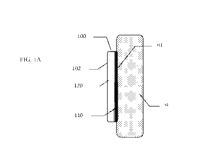
[0071] Figure lA shows a coating resulting from a gradual change in the mixing
ratio of the
coating components.
[0072] Figure 1B shows a coating resulting from a step-wise change in the
mixing ratio of the
coating components.
[0073] Figure 2A shows a schematic chart representing several scenarios of
changing ratio of
mixing of two components during the time of the delivery of the coating.
23
CA 02940449 2016-08-22
WO 2015/134267 PCT/US2015/017717
[0074] Figure 2B shows, a coating formed on tissue corresponding to the
scenario of Line 1 of
Figure 2A.
[0075] Figure 2C shows, a coating formed on tissue corresponding to the
scenario of Line 3 of
Figure 2A.
[0076] Figure 3 shows a schematic of a dispenser with the means of changing
the mixing ratio
of components.
[0077] Figure 4A shows a schematic of a dispenser with the means of changing
the mixing
ratio of components.
[0078] Figure 4B shows one embodiment of the inventive multi-component
applicator
illustrating the ability to select the mixing ratio of the different
components during application.
[0079] Figure 4C shows an alternate embodiment of the inventive multi-
component applicator
illustrating the ability to select the mixing ratio of the different
components during application.
[0080] Figures 5A-C show embodiments of the present invention.
[0081] Figures 6A-E show embodiments of the present invention.
[0082] Figures 7A-E show embodiments of the present invention.
[0083] Figures 8A-D show embodiments of the present invention.
[0084] Figures 9A-9F show embodiments of the present invention.
[0085] Figures 10A-C show embodiments of the present invention.
[0086] Figure 11 shows embodiment of the present invention.
[0087] Figures 12A-B show embodiments of the present invention.
[0088] Figure 13A-B show embodiments of the present invention.
[0089] Figure 14 shows embodiment of the present invention.
[0090] Figures 15A-C show embodiments of the present invention.
[0091] Figure 16 shows embodiment of the present invention.
[0092] Figures 17A-B show embodiments of the present invention.
[0093] Figure 18 shows embodiment of the present invention.
24
CA 02940449 2016-08-22
WO 2015/134267 PCT/US2015/017717
[0094] Figures 19 A-B shows coating comprising multiple layers and overlap
pattern
according to an embodiment of the present invention.
DETAILED DESCRIPTION OF THE INVENTION
[0095] The present invention relates to biomedical coatings, including sealing
agents, adhesives,
hemostatic agents, and adhesion preventing coatings, more specifically to
compositions and
devices to deliver such coatings, whereby the composition of the coating and
properties of the
coating are variable across the thickness of the coating. The present
invention also relates to
delivering biomedical coatings, including sealing agents, adhesives,
hemostatic agents, and
adhesion preventing coatings, from a single applicator in which the medical
professional selects
the composition and function desired at the time of delivery to a work surface
of a given tissue
site. The present invention further relates to delivering biomedical coatings,
whereby the
composition and function automatically changes during the delivery to a work
surface of the
given tissue site.
[0096] The present invention relates to an applicator and method of applying a
biologic fluid
agent comprising multiple fluid components to a work surface, and is
particularly, although not
exclusively, useful for applying biologic sealants, or other biologic fluid
agents, to biological
tissue to effect hemostasis, close wounds, apply skin grafts or achieve other
desirable therapeutic
results. More particularly, the invention relates to application of a multiple-
component tissue
sealant agent, one component of which comprises a polymerizable biological or
synthetic sealant
agent, for example fibrinogen, and the other component of which comprises a
biologically
acceptable polymerization catalyst or activator agent, for example, thrombin.
Other
polymerizable and activation agents may be used, as is understood by those
skilled in the art.
[0097] The present invention provides a surgeon or other user of a handheld
biologic or synthetic
fluid agent applicator with more flexibility, for example the ability to
deliver an agent through a
variable output biologic fluid agent applicator whereby the mixing ratio of
components forming
the agent changes automatically or manually by choice of user during the
application, resulting
in one composition forming a tissue-facing side of the coating, and another
composition forming
an opposing side of the coating.
[0098] An end result of the inventions described herein is an ability to
increase the flexibility
physicians need to deal with incised or otherwise traumatized bodily tissues
having a variety of
CA 02940449 2016-08-22
WO 2015/134267 PCT/US2015/017717
clinical needs. After a procedure on an internal organ, a physician primarily
needs to close the
incisions created. A secondary, but important, need is to prevent any
intermittent or continuous
leakage of fluids such as blood, or in the case of lung tissue, air. A third
need is to prevent or at
least minimize unwanted surgical adhesion formation that often takes place
between bodil.y
tissues post-operatively. These three different clinical needs have not yet
been addressed by a
singl.e material or procedure.
[0099] This disclosure will make available a hydrogel system and means of
delivering this
system. to simultaneously achieve advantageous properties that can address
multiple clinical
needs as described above. Methods will be disclosed to allow the formation of
hydrogel.s that can
m.ultifunction as a surgical adhesive and/or sealant and will also have
ex.cel.lent surgical adhesion
preventative properties or other supplementary properties. This discl.osure
describes hydrogel
systems and devices to deliver hydrogel precursors providing a compositional
variation to
address those different clinical needs. In some embodiments, this
compositional variation can be
a gradient orthogonal to the surface of the bodily tissue; i.e. a hydrogel
which changes in
composition, and thus in properties, as a function of the distance away from
the tissue upon
which it is applied. In other embodiments, this compositional variation is
effected in a step-wise
fashion, whereby part of the coating applied has a first composition, and the
coating applied on
top has a second composition, with the first and second compositions differ
only in mixing ratio
of the composition forming pre-cursors. The precursor components of the
hydrogel system of
choice are typically water soluble (before application), and are capable of
curing, usually by
cross-linking. It is a further objective of this disclosure to provide
different degrees of cross-
linking on demand; in a preferred application, the formed hydrogel is
absorbable.
[00100] During a surgical procedure, incisions are created to access the sites
of interest. Once
the intended objectives are achieved, these incisions are closed for healing.
in many cases, these
incisions or wounds caused by trauma are closed with sutures or staples.
Surgical adhesives also
have been used more and more often in the past decade for closing external
incisions. Recently, a
surgical adhesive focus has been in the area of absorbable adhesives,
potentially enabling their
use for internal incisions. Hydrogels containing PEG (polyethylene glycol)
moieties are of
particular interest. Multi-armed PEGs are examples of these hydrogel
components.
[00101] However, internal incisions require more than just a closure for
healing. Examples
include the anastomosis of a tubular structure having a lumen requires not
only the re-joining of
tissue, but also leakage prevention of the lurnen content. In these cases, a
surgical sealant is
26
CA 02940449 2016-08-22
WO 2015/134267 PCT/US2015/017717
required to seal the joint to prevent the leakage of lumen content. Moreover,
at the interface
between the incised tissue or organ and adjacent tissues or organs, surgical
adhesions can occur
due to biological responses. To prevent unwanted surgical adhesion formation,
several options
are currently available. One is the use of anti-inflammatory agents; another
approach is the use of
a barrier. Barrier materials used as adhesion preventative devices include
oxidized regenerated
cellulose (ORC) and polyethylene glycol (PEG) derivatives. Presently a surgeon
can select a
product that functions primarily in one of the four performance categories:
adhesive, sealant,
adhesion barrier, or hemostat. An object of this invention is to conveniently
provide a single
product that imparts two or more of these functions and to provide a
convenient method to allow
the surgeon to select the product characteristics at the time of appl.ication.
[00102] It is a further aspect of this invention to provide an applicator
system. that is capable of
applying components to result in a hydrogel in which there exists a gradient
of properties. That
is, properties of the hydrogel portion closest to the surface of the bodily
tissue may, for instance,
function as a surgicai adhesive or a surgical sealant (achieved for instance
by having a high
cross-link density) or hemostat. As one moves further from the surface, the
properties of the
hydrogel change (achieved for instance by having a lower cross-link density)
all.owing the
surface portion to exhibit adhesion barrier characteristics or other different
properties. Thus in
one aspect of the subject invention, a hydrogel is provided in which there is
gradient of cross-
link density or step-wise change in cross-link density as one moves
orthogonally from the
surface of the bodily tissue. These changes in cross-link density will result
in a gradient of
properties as one moves orthogonally from the surface of the 'bodily tissue.
[00103] To be clear, this invention, in one aspect, is directed towards the
delivery of known
materials (fibrinogen/thrombin or PEGs or other multiple components hydrogels)
discussed in
the patent or open literature or commercially available are commonly provided
as a material with
one pre-determined property to address one type of clinical need, for instance
as either a surgical
adhesive or as a surgical sealant or as a surgical adhesion barrier, or as a
hemostat, respectively.
[00104] It is an object of this disclosure to provide the surgeon with a
single device that has the
flexibility to conveniently deal with a number of clinical needs of bodily
tissues. To achieve this
objective, methods will be disclosed to allow the formation of materials
(particularly
fibrinogen/thrombin combinations and hydrogels) that can optionally function
as a hemostat,
and/or a surgical adhesive, and/or a surgical sealant, and/or will have
excellent surgical adhesion
preventative properties, with at least two of the above characteristics
present, as selected by the
27
CA 02940449 2016-08-22
WO 2015/134267 PCT/US2015/017717
surgeon at the time of the delivery of the coating components, that is at the
time of the surgical
application.
[00105] In one embodiment of the present invention the use of polyethylene
glycol (PEG)
derivatives, particularly multi-armed functionalized hydrogel precursors is
contemplated. In one
such case, an aqueous solution of a multi-armed PEG tipped with very reactive
esters groups
[e.g. based on N-hydroxy succinamide leaving groups] are reacted with an
aqueous solution of
multi-function amines [e.g. lysine or a multi-armed PEG tipped with amines],
to form biomedical
coatings of the present invention.
[00106] In the above case, the characteristics of the final product are
controlled by the initial
concentrations of the two solutions, and their relative mix rations. For
instance, if one views the
lysine solution as a cross-linker, it will be easy to see that the relative
amount of this component
employed will alter the crosslink density of the hydrogel so formed, and thus
its characteristics.
With a relatively low cross-link density, the resulting hydrogel is better
suited as an adhesion
preventative. With increased cross-link density, the hydrogel that is formed
is less swellable and
possesses higher mechanical properties. As cross-link density increases, the
resultant hydrogel
can function as a sealant; at still higher cross-link densities, the
mechanical properties are such so
as to allow its use as an adhesive.
[00107] Referring now to Figure I A, representing a schematic cross-sectional
view of one
embodiment of the present invention, coating 100 on tissue 20 has a tissue
facing surface 101
and an opposing surface 102. Coating 100 forming in situ on tissue 20 has a
mixing ratio of
components gradually changing, for example from high cross-linker percentage
to low cross-
linker percentage, resulting in high crosslinker concentration area 110 on
tissue 20 surface and
low crosslinker concentration area 120 adjacent to opposing surface 102. The
gradual change is
schematically indicated in Figure 1 by a shading gradient.
[00108] Referring now to Figure 1B, representing a schematic cross-sectional
view, according
to another embodiment of the present invention, coating 100 has a mixing ratio
of components
changing step-wise, for example from high cross-linker percentage to low cross-
linker
percentage, resulting in layer 110 with high crosslinker concentration, facing
tissue 20 surface
and adjacent to tissue facing surface 101, step-wise changing to layer 120
with low crosslinker
concentration adjacent to opposing surface 102 of coating 100. Layers 110 and
120 are
physically distinct layers in a sense that the composition of the layers is
different. Layers 110 and
28
CA 02940449 2016-08-22
WO 2015/134267 PCT/US2015/017717
120 are physiologically distinct in a sense that their interaction with tissue
is different due to
different properties of the layers formed by mixing components in different
mixing ratios.
[00109] Referring now to Figure 2A, examples of ratios of mixing upon
expressing the two-part
composition are shown in a format of a schematic chart representing the ratio
of mixing of two
components relative to coating delivery time or relative to distance from
tissue surface. From a
practical viewpoint, this corresponds to the time of expressing the mixture
from a delivery
device, as the initially expressed mixture will generally lie closest to the
tissue surface, while
later expressed material may lie upon the first applied layer. It is also to
be understood that in
some instances, one may choose to express the later mixture not only on the
previous layer but
also upon virgin (uncoated) tissue areas. The chart presented in Figure 2A,
which is not drawn to
scale, shows three exemplary mixing ratios of components, including ratio
0.25:1; ratio 1:1; and
ratio 4:1 which are step-wise changing as expression from the delivery device
progresses. Line 1
shows the mixing ratio changing step-wise from about 1:1 to about 4:1. Line 2
shows the mixing
ratio changing step-wise from 0.25:1 to 1:1 and then to 4:1. Line 3 shows the
mixing ratio
changing step-wise from about 1:1 to about 4:1 and then back to 1:1. To be
clear, a gradual
change in the mixing ratio is also within the scope of this invention as
described previously.
[00110] Referring now to Figure 23, coating 100, formed corresponding to the
scenario of Line
1 of Figure 2A, is schematically shown on tissue 20, comprising a layer 110a
formed on tissue
20 from mixture of 1:1 ratio and layer 120a formed from mixture with 4:1 ratio
on top of layer
110a. Referring now to Figure 2C, coating 100, formed corresponding to the
scenario of Line 3
of Figure 2A, is schematically shown, comprising layer 110a formed on tissue
20 from mixture
of 1:1 ratio, layer 120a formed from mixture of 4:1 ratio on top of layer
110a, and layer 110b,
formed from mixture of 1:1 ratio on top of layer 120a. Other mixing ratio
scenarios are possible
and will be easily apparent to these skilled in the art.
[00111] According to one embodiment of the present invention, coating 100 is
obtained by
altering the volume ratio (fraction) of the components of the coating during
application, while
maintaining a constant total volumetric throughput or allowing the total
volumetric throughput to
change during application. In one embodiment, the ratio of the component
streams changes, e.g.
instead of constantly combining a feed stream of 50% of solution A with 50% of
solution B,
coating 100 is initially applied by a feed stream of 50% of solution A with
50% of solution B,
and then changes the feed stream (continuously or abruptly) to a feed stream
of 30% of solution
A with 70% of solution B. This change can be achieved by maintaining a
constant total
29
CA 02940449 2016-08-22
WO 2015/134267 PCT/US2015/017717
volumetric throughput or by allowing the volumetric throughput to change
during application. In
the first case, if a total volumetric throughput of 0.2 ml/sec is delivered at
the start of the
application, the same total volumetric throughput of 0.2 mlisec will be
delivered at the second
stage of the application, but at a different A/B mix ratio.
[00112] According to another embodiment of the present invention, the supply
rate decreases
(or increases) for one of the components; the component volume ratio
(fraction) is altered, as will
the total volumetric throughput.
[00113] Various designs to regulate the volume during dispensing are
contemplated and will be
discussed in more detail. Referring now to Figure 3, schematically showing one
embodiment of
the present invention, delivery device 200 comprises component A container
210, component B
container 220, and optional component C container 230, inlet tubes 211, 221,
231, manifold 240
having means 245 to change the mixing ratio, optional pressurized air inlet
247, outlet tubes 250
terminating with optional mixing nozzle 255 and ejecting liquid non-cross-
linked components
schematically shown as stream 257 towards tissue 20 and forming coating 100.
Component A
can be a cross-linkable polymer, component B can be a cross-linker, and
optional component C
can be a diluent (such as water or other non-cross-linkable material, such as
non-functionalized
PEG, gelatin solution, protein solution, or similar). In application, means
245, such as valve,
changes the expression of the component mixture after a portion of coating 100
has been applied
to tissue 20, forming layers 110 and 120 on tissue 20.
[00114] Table 1 shows, for illustration purposes, exemplary volume ratios of a
three-component
multi-part biomedical composition forming the coating of the present
invention. In one
embodiment, the initial mixing ratio corresponds to case 1, i.e. with
components A and B
delivered in ratio 1:1 and no component C for the overall mixing ratio 1:1:0.
The expression can
then change to case 2, with decrease in component B and addition of component
C, with A:B:C
ratio of 1:0.5:0.5. Alternatively, the expression can change from case 1 to
case 3, with the same
expression of components A and B, and addition of component C in equal volume,
with A:B:C
ratio of 1:1:1. In yet another scenario, the expression changes from case 1 to
case 4, with the
same volumetric expression of component A, no expression of component B, and
addition of
component C in equal volume, with A:B:C ratio of 1:0:1.
Table 1
Exemplary Volume Ratios of a Three-Component Coating of the Present invention
CA 02940449 2016-08-22
WO 2015/134267 PCT/US2015/017717
Case Component A Component B Component C
1 1 1 0
1 0.5 0.5
3 1 1 1
4 1 0 1
[00115] According to another embodiment of the present invention, there is
provided a dual
chamber for holding components A and B separately and a spray head to regulate
their supply.
This design can, abruptly (step-wise) or continuously, change the supply of
one of the
components on demand by the user. A gear pressing against the supply of
component B can be
used to regulate/control the volume delivered to the nozzle. A further
refinement of this
embodiment allows the control gear to be set at a plurality of levels,
providing additional control
to the surgeon. This leads to different degree of reaction therefore different
properties to address
different clinical needs. Instead of a gear mechanism, a bladder can also be
used to
regulate/control the delivery volume.
[00116] According to yet another embodiment of the present invention, the
concentration of one
or all components can be altered. In this embodiment, delivery device will
have triple chambers
for holding component A, B, and C (the diluent) and a spray head to regulate
the supply of
component C (diluent). This design also allows abruptly changing the supply on
demand by the
user. The control regulates the supply of diluent starting from "complete off"
to "open at
multiple levels". The diluent is to merge with at least one of the reactive
component first to
ensure the dilution of this component before mixing with the other reactive
component.
Alternately, the diluent stream may be added during the spraying process to
allow mixing at the
droplet level. The potential candidates for a diluent are either a solvent for
the materials (most
likely water in this case) or a less reactive component.
[00117] According to still another embodiment of the present invention, one
component can be
changed to a less reactive component. In this embodiment, component A is first
delivered in a
mixture with component B, then switching to delivery of component A in mixture
with
component C. A multiple-chambers bottle, connected to an adaptor, and then
connected to a
31
CA 02940449 2016-08-22
WO 2015/134267 PCT/US2015/017717
spray head can be utilized as a delivery device. An adaptor can serve as a
toggle switch to
change the connection of different components to one channel of the spread
nozzle. The other
nozzle may be connected to one constant component.
[00118] According to still another embodiment of the present invention, as
schematically
illustrated in Figure 4A, component A sprayer 270 has a feature to introduce
component B.
Piercing stem 271 connects container 228 with component B to sprayer 270 with
a pierceable
cap 273. Valve 272, which controls the mixing ratio, is installed on piercing
stem 271 with the
Venturi effect ensuing component B intake. For different clinical needs,
container 228 is then
removed and another one containing different component (such as component C)
is connected. In
an additional embodiment, container 228 can have multiple chambers, which can
be connected to
sprayer 270 through an adapter (not shown) that can switch the connection
between the different
chambers.
[00119] Figure 4B shows yet another embodiment of the present invention, with
delivery device
900 with actuator assembly 910, containing actuators 911, 912, and 913
removably connected to
multiple spray pumps, 921, 922, and 923, which are connected to multiple
chambers, 951, 952,
and 953 arranged within optional holder 950, with chambers separately
containing flowable
components 961, 962, and 963. Nozzles 931, 932, and 933 are provided on spray
pumps with
feed tubes 941, 942, and 943 submerged under liquid level in chambers and
connected to pumps.
Actuators 911, 912, and 913 depressing or actuating spray pumps 921, 922, and
923 result in
spraying of flowable components 961, 962, and 963 through nozzles 931, 932,
and 933 with
flowable components 961, 962, and 963 supplied via feed tubes 941, 942, and
943. Lever 915
releasably restrains actuator 913 in the actuator assembly 910. When lever 915
is pulled to
release the actuator 913, as shown schematically by an arrow, spring 914
pushes the actuator 913
to the same level as actuators 911 and 912. At this time, lever 915 reengages
and locks actuator
913 in place. This locking mechanism allows all actuators to engage the pumps
at the same time
to express flowable components 961, 962, and 963. This locking process is
reversible and thus
allows the users to change the mixing ratio at any time as needed.
Additionally, lever 915 can be
set at unlock position leading to a continuous variation of component 963.
[00120] In operation, container 951 is filled with component 961, such as a
crosslinker;
container 952 is filled with component 962, such as a crosslinkable
prepolymer; container 953 is
filled with component 963, such as a diluent to change the ratio between
crosslinkable
prepolymer and crosslinker, which can be another crosslinkable prepolymer or
water. When
32
CA 02940449 2016-08-22
WO 2015/134267 PCT/US2015/017717
actuator assembly 910 is depressed to engage the pumps, pistons 911 and 912
activate pumps
921 and 922 to express components 961 and 962 via nozzles 931 and 932. After
the lever 915 is
pulled to release and relock actuator 913 in a new position, pump 923 will
also be activated when
piston assembly 910 is depressed thus changing the mix ratio.
[00121] Figure 4C shows another embodiment, with delivery device 1000 having a
piston
assembly 1010, containing actuators 1011, 1013, and 1014 engageably connected
to spray pumps
1021, 1022, and 1023 attached to chambers 1051, 1052, and 1053 arranged within
optional
holder 1050, with chambers separately containing flowable components 1061,
1062, and 1063.
Nozzles 1031, 1032, and 1033 are provided on spray pumps with feed tubes 1041,
1042, and
1043 submerged under liquid level in chambers and connected to pumps. Levers
1016 and 1017
initially restrain actuators1011 and 1013 in actuator assembly 1010. When the
levers 1016 and
1017 are pulled as shown by arrows to release actuators 1011 and 1014, springs
1012 and 1015
will push actuators 1011 and 1014 to the same level as actuator 1013. At this
time levers 1016
and 1017 will reengage and lock actuators 1011 and 1014 in place. This allows
all pistons to
engage all pumps at the same time to express components from each pump. In
certain
applications, actuators1011 and 1014 can be engaged separately. This process
is reversible thus
allows the users to change the mixing ratio at any time as needed.
[00122] In operation, container 1051 is filled with component 961, such as a
crosslinker, and
container 1052 is filled with component 962, such as a crosslinkable
prepolymer, and the
container 1053 is filled with component 963, such as an alternative
crosslinker. By choosing to
activate either actuator 1011 or 1014 or both will achieve different ratio
between crosslinkable
prepolymer and crosslinker.
[00123] According to further embodiments of the present invention a two-part
adhesive (or
sealant) coating composition (such as a PEG-based multi-arm macromer with
ester functionality
and multi-arm crosslinker with amine functionality) is mixed in a variable
ratio in situ to result in
a coating with highly adhesive/sealing properties (high concentration of cross-
linker) at the tissue
contacting surface of the coating, step-wise or continuously changing to non-
adhesive, adhesion-
preventive properties (low concentration of crosslinker) at the opposite
surface of the coating.
The composition is delivered uninterruptedly from a single applicator delivery
device (having
two chambers for storing two-part composition) and two separate discharge
nozzles (or a single
mixing discharge nozzle), providing a continuous change in the mixing ratio,
resulting in a
compositional gradient orthogonal to the tissue interface or step-wise
compositional change at a
33
CA 02940449 2016-08-22
WO 2015/134267 PCT/US2015/017717
plane parallel to the tissue interface. The delivery device has control means
for continuously or
step-wise changing the mixing ratio. The delivery device has an optional third
chamber
containing either diluent or a weaker crosslinker.
[00124] According to further embodiments of the present invention, there are
provided methods
and delivery devices for forming bi-layer or multi-layer coatings using
variable mixing ratios of
two-part compositions. Briefly, in one embodiment, a two-part coating or
sealant or hemostatic
composition is applied from a delivery device whereby the mixing ratio of two
components of
the coating changes step-wise from. one ratio to another ratio during the
expression, resulting in
the first layer of the coating having one composition (e.g. hemostatic), and
second layer of the
coating having another composition (e.g. sealant and/or anti-adhesion). The
mixing ratio changes
due to changing of the relative expression rate of one component relative to
another, i.e. first
component is expressed at one rate, then switches to a faster or slower rate.
Thus the delivery
device provides automatic switch from one mixing ratio to another mixing ratio
as expression
progresses.
[00125] The delivery devices of the present invention automatically and
uninterruptedly switch
from. the first mixing ratio to the second mixing ratio as the expression
progresses with no
additionai user input resulting in bi-layer or tri-layer coatings.
[00126] Non-limiting exampl.es of two-part adhesives (or sealants) are:
a) Fibrinogen:thrombin in variable ratios such as about 1:1 switching during
applying the coating
to ratio of about 5:1 or vice versa. Other ratios are changing from. 1:1 to
1:2; 1:1 to 10:1, and
similar. The switching can occur, for example, half-way during applying of the
coating.
b) PEG-based multi-arm. macromer with ester functionality and multi-arm
crosslinker with amine
functionality) which is mixed in a variable ratio to result in a coating with
highl.y
adhesive/sealing properties (high concentration of cross-linker) at the tissue
contacting surface of
the coating, then step-wise automatically changing to non-adhesive, adhesion-
preventive
properties (low concentration of crossl.inker) at the opposite surface of the
coating.
c) Any cross-linking agent and polymerizable monom.er.
d) Polymeric coating and a diluent.
[00127] Generally, switching can occur at any time during coating delivery,
such as after
delivering 10%; 20%, 30%, 50%; 75%, 90% of the coating material. Preferably
switching form.
34
CA 02940449 2016-08-22
WO 2015/134267 PCT/US2015/017717
one ratio to another occurs after delivering about 30%, 50%; or 70% of the
coating material.
There can be an optional pause of several seconds before starting delivering
of the second
mixing ratio.
[00128] According to an embodiment of the present invention, the composition
is delivered
uninterruptedly from a single delivery device (having at least two syringes
for storing the two-
part composition) and at least two separate discharge nozzles (or a single
mixing discharge
nozzle). At least one of the syringes changes the component expression rate
during expression.
According to embodiments of the present invention, at least one syringe of a
dual syringe
delivery device has two diameters; a piston engaged with a ring-shaped gasket
is used to express
component from large diameter compartment and the same piston disengaged from
the gasket is
used to express component from the small diameter compartment. The gasket
engages/disengages at the border between large diameter and small diameter
compartments as
the piston pushed by a user progresses through the syringe.
[00129] Referring now to Figure 5A, a schematic cross-sectional view of an
embodiment of a
first syringe 310 of multi- syringe delivery device 300 (not shown in Figure
5) is presented. First
syringe 310 comprises a generally tubular hollow barrel 320 extending along an
axis and having
a proximal end 330 and an opposing distal end 340 spaced axially behind
proximal end 330.
Barrel 320 comprises a first retention compartment or large diameter
compartment 322 having
internal diameter DI and positioned closer to distal end 340 and a second
retention compartment
or small diameter compartment 324 having internal diameter D2 and positioned
closer to
proximal end 330, both compartments 322 and 324 spaced axially and shaped as
hollow
cylinders, with larger diameter D1 at least 10% larger than smaller diameter
D2. An elongated
plunger 350 projects axially rearward out of distal end 340 of barrel 320 and
moveable axially in
barrel 320 from distal end 340 to proximal end 330. Plunger 350 has a front
end 352 and an
opposing rear end 354, and comprises an elongated rod 355, with optional
handle 360 mounted
at the rear end 354 on rod 355, with piston 370 mounted at the front end 352
on rod 355. Piston
370 has substantially cylindrical shape, and has a diameter closely matching
diameter D2 for
tight but slidable fit inside small diameter compartment 324. Ring-shaped or
hollow cylinder
shaped gasket 380 with an optional barb or lip 382, has outside diameter
closely matching
diameter DI for tight but slidable fit inside large diameter compartment 322,
and inside diameter
closely matching diameter D2 so that piston 370 can tightly but slidably fit
inside gasket 380.
CA 02940449 2016-08-22
WO 2015/134267 PCT/US2015/017717
Nozzle 390, which is located on proximal end 330 of barrel 320, expresses
component A from
first syringe 310 and can optionally be capped by a removable cap 392.
[00130] Figure 5A shows the first syringe 310 prior to expressing component A,
or during
expressing component A from large diameter compartment 322 by advancing
plunger 350
towards proximal end 330, but with piston 370 remaining within large diameter
compartment
322, corresponding to high volumetric expression rate from first syringe 310.
Gasket 380 always
remains within large diameter compartment 322. In operation, piston 370
engaged as shown with
gasket 380 and held in engaged position by optional barb or lip 382 advances
through large
diameter compartment 322 towards proximal end 330 or towards nozzle 390,
expressing
component A through nozzle 390 at a high volumetric expression rate. As piston
370 engaged
with gasket 380 reaches small diameter compartment 324, gasket 380 remains in
large diameter
compartment 322 and disengages from piston 370, while piston 370 driven by
plunger 350
continues advancing into small diameter compartment 324. Referring now to
Figure 5B, first
syringe 310 is shown in further operation, after expressing component A from
large diameter
compartment 322 and beginning expression from small diameter compartment 324,
corresponding to low volumetric expression rate from first syringe 310. As can
be seen from
Figure 5B, as piston 370 driven by plunger 350 has advanced into small
diameter compartment
324, gasket 380 cannot advance into small diameter compartment 324 and remains
in large
diameter compartment 322. As piston 370 advances within small diameter
compartment 324,
volumetric expression rate from first syringe 310 will decrease, provided that
the linear speed of
advancing plunger 350 remains the same. Referring now to Figure 5C, first
syringe 310 is shown
upon completion of the expression of component A with piston 370 stopped at
proximal end 330
of barrel 320.
[00131] Upon change from expressing from large diameter compartment 322 to
expressing from
small diameter compartment 324, the rate of component expression will change
proportionally to
the square ratio of diameters DI to D2, if the linear speed of advancing
plunger 350 remains the
same. If plunger advances within a cylindrical body at a linear speed S, the
volumetric
expression rate V will be a function of diameter D:
D2
V= Sir ¨4
[00132] If plunger advances at a speed S=0.5 cm per second and D1 = 1.5 cm and
D2 = 1.0 cm,
the volumetric expression rate will be for large diameter compartment 322, 'VI
= 0.88 mlls and
36
CA 02940449 2016-08-22
WO 2015/134267 PCT/US2015/017717
for small diameter compartment 324: V2 = 0.39 ml/s, resulting in changing
expression rate by
2.25 times. If plunger advances at a speed S=I cm per second and DI = 2 cm and
D2 = 1 cm, the
volumetric expression rate will be for large diameter compartment 322: V1=
3.14 ml/s and for
small diameter compartment 324: V2 =0.785 ml/s, resulting in changing
expression rate by 4
times. As shown above, Figure 5A shows position corresponding to higher
expression rate of
component A from first syringe 310 and Figure 5B shows position corresponding
to lower
expression rate of component A from first syringe 310.
[00133] Referring now to Figures 6A-E, Figure 6A shows gasket 380 with
external diameter
matching diameter DI and with gasket opening 381 having diameter matching
diameter D2;
Figure 6B shows piston 370 with diameter matching diameter D2, with piston 370
mounted on
rod 355; Figure 6C shows gasket 380 with external diameter matching diameter
Di, whereby
gasket 380 is mounted on piston 370. Referring now to Figure 6D, gasket 380 is
shown with
optional barb or lip 382 having diameter of Db. Diameter Db is smaller
relative to diameter D2,
with difference of from about 0.050 mm to about 3 mm, more preferably 0.1 mm
to 2 mm, such
as 0.5 mm or I mm. Barb or lip 382 serves to ensure tight engagement of gasket
380 with piston
370 during advancement through large diameter compartment 322, and then
separation of piston
370 from gasket 380 by pushing piston 370 over barb 382 whereby piston 370
disengages from
gasket 380 and enters smaller diameter compartment 324. Referring now to
Figure 6E, an
embodiment of first syringe 310 corresponding to cross-sectional views of
Figures 5A-C is
shown in a prospective view.
[00134] Referring now to Figures 7A-E, several embodiments and arrangements of
gasket 380
and piston 370 are shown in a schematic cross-sectional view, for position of
gasket 380 engaged
with piston 370 within large diameter compartment 322. Figure 7A shows gasket
380 having
optional barb 382 on proximal side of gasket 380 adapted to increase force
necessary to
disengage piston 370 from gasket 380. Figure 7B shows gasket 380 having
optional barb 382 on
both proximal and distal side of gasket 380 adapted to increase force
necessary to disengage
piston 370 from gasket 380. Figure 7C shows barb 382 positioned inside gasket
380 and fitting
within a cutout or grove 383 within piston 370. Figure 7D shows piston 370
having an area of
smaller diameter 384 at proximal end, facilitating entry of piston 370 into
small diameter
compartment 324 (not shown in Figure 7 D). Figure 7E shows barb 382 positioned
inside gasket
380 and fitting within a cutout or grove 383 within piston 370 which is
extending beyond gasket
380 for more reliable engagement of gasket 380 and piston 370.
37
CA 02940449 2016-08-22
WO 2015/134267 PCT/US2015/017717
[00135] The embodiments of figure 7B, 7C, and 7E also enable the movement of
plunger 350
not only towards proximal end 330, but also towards distal end 340, without
disengaging piston
370 from gasket 380 in large diameter compartment 322. This enables filling of
syringes 310 by
pulling plunger 350 from the position shown in Figure 5C, towards distal end
340, with fluid
entering syringe 310 through nozzle 390. During filling of the syringe 310, as
piston 370 enters
large diameter compartment 322, piston 370 engages with gasket 380 with the
help of barb 382
and optionally cutout 383, and then piston 370 continues moving though large
diameter
compartment 322 towards distal end 340 engaged with gasket 380, resulting in
filling of syringe
310 through nozzle 390.Referring now to Figures 8A-D, alternative embodiments
of first syringe
310a and 310b are presented in a schematic cross-sectional view.
Differentiating from the
embodiments shown in Figures 5A-C, in embodiments of first syringe 310a and
310b shown in
Figures 8A-D, barrel 320a comprises a first retention compartment or large
diameter
compartment 322a positioned closer to proximal end 330 and a second retention
compartment or
small diameter compartment 324a positioned closer to distal end 340. in the
embodiments
presented in Figures 8A-D, gaskets 380a and 380b are positioned in large
diameter compartment
322a and have openings 386 with diameter D2a smaller than diameter D2 of
piston 370, such as
from 10% smaller to 90% smaller. in the embodiment presented in Figures 8B and
8D, gasket
380b, while similar to gasket 380a, also has a gasket cutout 385 adapted to
snugly accommodate
piston 370. The elements of embodiments of Figures 8A-C are shown in more
details in Figures
9A-G. Figure 9A shows ring-shaped gasket 380a of Figures 8A and 8C having
external diameter
matching D1, and opening 386 having diameter D2a. Figure 9B shows piston 370
with diameter
matching diameter D2, piston 370 mounted on rod 355. Figures 9C and 9D show
gasket 380b of
Figures 8B and 8D similar to gasket 380a but further having cutout 385 of
diameter D2. Figure
9E shows embodiment of first syringe 310a or 310b corresponding to cross-
sectional views of
Figures 8A-D but shown in a prospective view.
[00136] Figures 9F and 90 show an embodiment of gasket 380b and piston 370,
with optional
barb 382 positioned inside gasket 380 and fitting within an optional cutout or
grove 383 within
piston 370 for more reliable engagement of gasket 380b and piston 370. Figure
9F shows gasket
380b and piston 370 engaged, while Figure 9G shows only gasket 380b.
[00137] Figures 8A and 8B show respectively the first syringe 310a and 310b
prior to
expressing component A or during expressing component A from small diameter
compartment
324a by advancing piston 370 towards proximal end 330, but with piston 370
remaining within
38
CA 02940449 2016-08-22
WO 2015/134267 PCT/US2015/017717
small diameter compartment 324a. Gaskets 380a and 380b always remain within
large diameter
compartment 322a. In operation, piston 370 advances through small diameter
compartment 324a
towards proximal end 330 or towards nozzle 390 moving component A from small
diameter
compartment 324a through openings 386 and through large diameter compartment
322a thus
expressing component A through nozzle 390 at a lower volumetTic expression
rate. As piston
370 approaches large diameter compartment 322a, it engages with gasket 380a or
380b, blocking
opening 386, after which piston 370 continues advancing within large diameter
compartment
322a together with gaskets 380a or 380b.
[00138] Referring now to Figures 8C and 8D, first syringes 310a and 310b are
shown in further
operation, after expressing component A from small diameter compartment 324a
and beginning
expression from large diameter compartment 322a. As can be seen, within large
diameter
compartment 322a piston 370 advances towards proximal end 330 engaged with
gaskets 380a or
380b, with volumetric expression rate from syringes 310a and 310b increasing,
provided that the
linear speed of advancing plunger 350 remains the same. Openings 386 are big
enough for the
fluid, such as component A, to easily pass though openings 386 as piston 370
advances through
small diameter compartment 324a, without gaskets 380a, 380b moving within
large diameter
compartment 322a. Openings 386 can be adjusted so that for higher viscosity
fluids the cross-
sectional size of openings is greater. The combination of the cross-sectional
area of opening 386
and the tight fit of gaskets 380a, 380b within the syringe prevents the
movement of the gaskets
380a, 380b before piston 370 engages with gaskets 380a, 380b at the border
between large
diameter compartment 322a and small diameter compartment 324a, whereby piston
370 starts
physically pushing on gaskets 380a, 380b thus moving gaskets through large
diameter
compartment 322a. Openings 386 can be non-circular or circular, in which case
openings 386
can be from about 1 mrn in diameter to about 10 mm in diameter, more
preferably 2 to 8 mm in
diameter, such as 3 mm, 4 mm, or 5 nun in diameter.
[00139] Similarly to the embodiments of Figures 7B, 7C, 7E, the embodiment of
Figures 9F and
9G also enables the movement of plunger 350 not only towards proximal end 330,
but also
towards distal end 340, without disengaging piston 370 from gasket 380b in
large diameter
compartment 322a. This enables filling of syringes 310b of Figures 8B, 8D by
pulling plunger
350 from initial position where piston 370, engaged with gasket 380b in
proximity to proximal
end 330, towards distal end 340, with fluid entering syringe 310b through
nozzle 390. During
filling of the syringe 310b, piston 370 moves through large diameter
compartment 322a engaged
39
CA 02940449 2016-08-22
WO 2015/134267 PCT/US2015/017717
with gasket 380b with the help of barb 382 and cutout or groove 383, as shown
in Fig. 8D (barb
382 and cutout or groove 383 are not shown in Figure 8D). As piston 370 enters
small diameter
compartment 324a, piston 370 disengages from gasket 380b, and then piston 370
continues
moving though small diameter compartment 324a towards distal end 340,
resulting in filling of
syringe 310 through nozzle 390 as also shown in Figure 8B (barb 382 and cutout
or groove 383
are not shown in Figure 8B).
[00140] Embodiments of first syringe 310, 310a, and 310b illustrated above
provide for one
step-wise change in expression rate of component A. According to another
embodiment of the
present invention, more step-wise changes in expression rate can be
accomplished by having
more than two compartments of different diameters comprising generally tubular
hollow barrel
of first syringe, such as three compartments of different diameters, with two
step-wise changes in
expression rate. As shown in Figures 10A-C, in another embodiment of the
present invention,
first syringe 410 comprises generally tubular hollow barrel 420 having a
proximal end 330 and
an opposing distal end 340 spaced axially behind proximal end 330. Barrel 420
comprises a first
retention compartment or large diameter compartment 422 having internal
diameter DI and
positioned closer to proximal end 330, a second retention compartment or small
diameter
compartment 424 having internal diameter D2 and positioned closer to distal
end 340, and an
intermediate diameter compartment 426 having internal diameter D3 and
positioned between
large diameter compartment 422 and small diameter compartment 424. Nozzle 390,
which is
located on proximal end 330 of barrel 420, expresses component A from first
syringe 410. An
elongated plunger 350 projects axially rearward out of distal end 340 and
axially slidable in
barrel 420 driving piston 370 from distal end 340 to proximal end 330. Piston
370 has a diameter
closely matching diameter D2, for tight but slidable fit inside small diameter
compartment 424.
[00141] Ring-shaped gasket 480a in intermediate diameter compartment 426 has
outside
diameter that closely matches diameter D3 for tight but slidable fit inside
intermediate diameter
compartment 426. Ring-shaped gasket 480b in large diameter compartment 422 has
outside
diameter that closely matches diameter DI for tight but slidable fit inside
large diameter
compartment 422. Gaskets 480a and 480b have openings 486a and 486b with
diameter smaller
than diameter D2 of piston 370, such as from 10% smaller to 90% smaller.
[00142] Figure 10A shows the first syringe 410 prior to expressing component A
or during
expressing component A from small diameter compartment 424 by advancing piston
370
towards proximal end 330, but with piston 370 remaining within small diameter
compartment
CA 02940449 2016-08-22
WO 2015/134267 PCT/US2015/017717
424. Gasket 480a remains within intermediate diameter compartment 426 and
large diameter
compartment 422. Gasket 480b remains within large diameter compartment 422. In
operation,
piston 370 advances through small diameter compartment 424 towards proximal
end 330 moving
component A from small diameter compartment 424 through openings 486a and 486b
and
through intermediate diameter compartment 426 and large diameter compartment
422 thus
expressing component A through nozzle 390 at a low volumetric expression rate.
As piston 370
approaches intermediate diameter compartment 426, it engages gasket 480a,
blocking opening
486a. As shown in Figure 10B, piston 370 then continues advancing within
intermediate
diameter compartment 426 with gasket 480a moving in front of piston 370. As
piston 370 with
gasket 480a approaches large diameter compartment 422, gasket 480b engages,
blocking gasket
opening 486b. As shown in Figure 10C, piston 370 then continues advancing
within large
diameter compartment 422 with gaskets 480a and 480b moving in front of piston
370.
[00143] As it is clear from the above description and Figures 1 OA-C, the
volumetric expression
rate is lowest when piston 370 advances within small diameter compartment 424;
volumetric
expression rate is intermediate when piston 370 advances within intermediate
diameter
compartment 426; and volumetric expression rate is highest when piston 370
advances within
large diameter compartment 422; the changes in volumetric expression rate
occur step-wise,
increasing as piston moves form one compartment to another, provided that the
linear speed of
advancing plunger 350 remains essentially the same.
[00144] in certain embodiments of the present invention, first syringe can
have a plurality of
compartments of increasing size, resulting in multiple step-wise increases in
expression rate,
each increase can be relatively small, such as increase of 10% to 50%, such as
20% increase.
Referring now to Figure 11, first syringe 510 has barrel 520 comprising 5
compartments, with
piston 370 disposed in smallest compartment, and gaskets 580a, 580b, 580c, and
580d positioned
in compartments of increasing diameter. Operation of first syringe 510 is
similar to described
above for first syringe 410.
[00145] As shown above, in certain embodiments of the present invention, first
syringe can
have a plurality of compartments arranged sequentially from distal end to
proximal end, whereby
diameter of the compartments goes from smaller to larger from distal end to
proximal end, or
vice versa, from larger to smaller from distal end to proximal end, resulting
in respectively
increase in expression rate, or decrease in expression rate. In other
embodiments described
below, diameter of the compartments goes from smaller to larger and then back
to smaller from
41
CA 02940449 2016-08-22
WO 2015/134267 PCT/US2015/017717
distal end to proximal end, or vice versa from larger to smaller and then back
to larger from
distal end to proximal end, resulting in respectively lower-higher-lower
expression rate, or
higher-lower-higher expression rate.
[00146] Referring now to Figure 12A, in one embodiment of the present
invention, first syringe
610 comprises barrel 620 which comprises a plurality of compartments arranged
sequentially
from distal end 340 to proximal end 330, whereby diameter of compartments goes
from smaller
to larger and then back to smaller, resulting in expression rate that is
initially lower, then
increases, and then goes back to lower rate. Barrel 620 comprises at the
distal end 340 second
retention compartment or small diameter compartment 624, and at the proximal
end 330 another
second retention compartment or small diameter compartment 624a, with first
retention
compartment or large diameter compartment 622 disposed between small diameter
compartments 624a and 624. Small diameter compartments 624a and 624 have the
same internal
diameters equal to external diameter of piston 370 and same or different
lengths, with internal
diameters of small diameter compartments 624a and 624 in all cases smaller
than the internal
diameter of large diameter compartment 622. Piston 370 in small diameter
compartment 624 and
ring-shaped gasket 380 having opening 381 and barb or lip 382 are disposed in
large diameter
compartment 622.
[00147] In operation, piston 370 advances through small diameter compartment
624, resulting
in low expression rate; then approaching large diameter compartment 622 piston
370 engages
with gasket 380, after which piston 370 engaged with gasket 380 advances
through large
diameter compartment 622, resulting in high expression rate; approaching small
diameter
compartment 624a piston 370 disengages from gasket 380 and then piston 370
advances through
small diameter compartment 624a, resulting in low expression rate.
[00148] Referring now to Figure 12B, in another embodiment of the present
invention, first
syringe 710 comprises barrel 720 which comprises a plurality of compartments
arranged
sequentially from distal end 340 to proximal end 330, whereby diameter of
compartments goes
from larger to smaller and then back to larger, resulting in expression rate
that is initially higher,
then decreases, and then goes back to higher rate. Barrel 720 comprises first
retention
compartment or large diameter compartment 722 at the distal end 340, and
another first
retention compartment or large diameter compartment 722a at the proximal end
330, with second
retention compartment or small diameter compartment 724 having internal
diameter equal to
diameter of piston 370, with the small diameter compartment 724 disposed
between larger
42
CA 02940449 2016-08-22
WO 2015/134267 PCT/US2015/017717
diameter compartments 722a and 722. Larger diameter compartments 722a and 722
can have the
same diameters and lengths or different diameters and lengths (as shown in
Figure 12B), but
internal diameters of larger diameter compartments 722a and 722 are in all
cases larger than the
internal diameter of small diameter compartment 724. Piston 370 positioned in
large diameter
compartment 722 engages with ring-shaped gasket 380 having barb or lip 382.
Ring-shaped
gasket 380a with opening 386 is positioned in large diameter compartment 722a.
[00149] In operation, piston 370 together with ring-shaped gasket 380 advances
through large
diameter compartment 722, resulting in high expression rate; before entering
small diameter
compartment 724 piston 370 disengages from gasket 380, with gasket 380
remaining in large
diameter compartment 722, after which piston 370 advances through small
diameter
compartment 724, resulting in low expression rate; upon entering large
diameter compartment
722a, piston 370 engages gasket 380a and blocks opening 386, after which
piston 370 advances
together with gasket 380a through large diameter compartment 722a, resulting
in high expression
rate.
[00150] Referring now to Figures 13A-B and 14, dual syringe delivery device
300 of the present
invention is shown in a schematic cross-sectional view and in a schematic 3D
view, with device
300 comprising first syringe 310 having barrel 320 containing component A and
second syringe
311 having barrel 321 containing component B, with barrel 320 and 321
optionally joined side-
by-side by connecting means or linkages 301 in a fixed position relative to
each other (linkages
301 not shown in Figure 14). In the embodiment shown in Figure 13, first
syringe 310 is
substantially similar to embodiment of first syringe 310 as shown in Figures
5A-C. Second
syringe 311 can be a standard construction syringe with a hollow cylindrical
barrel 321 of the
same diameter throughout, which will provide a constant relative expression
rate. Piston 371 of
second syringe 311 is mounted on rod 356 on proximal end, with optional handle
361 mounted
on rod 356 on distal end. Optional handles 360 and 361 are interconnected with
a bar 362 to
ensure joint movement of pistons 370 and 371 for simultaneous expression of
components A and
B. Optionally, handles 360 and 361 are not used and instead bar 362 is
directly attached to rods
355 and 356, as shown in Figure 14. Nozzles 390 and 391 are optionally
connected to an
optional mixing manifold 393 for intermixing and simultaneous expression of
the resulting
mixture through a single expression port 394. In an alternative embodiment (as
shown in Figure
14) no mixing manifold 393 is used, and components A and B are simultaneously
expressed
through nozzles 390 and 391 without mixing.
43
CA 02940449 2016-08-22
WO 2015/134267 PCT/US2015/017717
[00151] In operation, as the user depresses bar 362, components A and B are
expressed at an
relative expression ratio proportional to square of the ratio of diameters of
compartments of first
syringe 310 and second syringe 311 where pistons 370 and 371 are positioned.
Pistons 370 and
371 are advancing at the same speed towards proximal end 330, with the
distance from pistons
370 and 371 to proximal end 330 can be substantially the same throughout the
expression of
components A and B. In the embodiment shown in Figures 13A-B and 14, the
initial relative
expression ratio of components A and B is about 1:1 and corresponds to
positions of pistons 370
and 371 shown in Figure 13A, with piston 370 in large diameter compartment
322. As
expression of components A and B progresses, piston 370 reaches small diameter
compartment
324 of barrel 320 of first syringe 310 and disengages from gasket 380, whereby
relative
expression rate of component A decreases, corresponding to positions of
pistons 370 and 371
shown in Figure 13B. The relative expression rate of component B remains the
same throughout.
For the geometry shown in the figure 13, expression ratio will change from
(component A:
component B) equal to about 1:1 to expression ratio equal to about 0.4: 1.
[00152] The speed of depressing of bar 362 by a user can affect the overall
expression rate of
both components A and B. However the volumetric expression ratio is
independent of the speed
of advancing pistons and gaskets in first syringe 310 and second syringe 311,
with ratio of
component A: component B expression remaining independent of the speed of
coating delivery
defined by the speed of depressing the bar 362. Thus for the embodiment in
Figures 13A-B and
14, the expression ratio will change from (component A: component B) equal to
about 1:1 to
expression ratio equal to about 0.4: 1 while the coating delivery speed or
spray rate from single
expression port 394 can vary over a wide range of speeds, with coating
delivered for instance at
0.1 ml/s, 0.5 ml/s, 1 ml/s, or 5 ml/s.
[00153] Optionally, there can be a pause when switching from the components
mixed in the
initial expression ratio of components A and B to the second (or final)
expression ratio, such as
from equal to about 1:1 to expression ratio equal to about 0.4: 1 as in the
description above. The
optional pause can be from about 1 second to a few minutes, such as 5 seconds,
10 seconds, 30
seconds, or 60 seconds. The optional pause can be used to allow partial or
full curing of the
applied coating corresponding to the mixture of components in the initial
expression ratio, prior
to applying the mixture of components in the second (or final) expression
ratio.
[00154] In other embodiments of device 300 of present invention, fist syringe
310 can be any
of previously described embodiments of first syringe, including first syringe
310, 310a, 310b,
44
CA 02940449 2016-08-22
WO 2015/134267 PCT/US2015/017717
410, 510, 610, 710, and variants thereof as described above. Second syringe
311 can be any
standard construction syringe with a hollow cylindrical barrel 321 of the same
diameter
throughout, which will provide constant expression rate. In alternative
embodiments of the
present invention, second syringe 311 can al.so be of construction
corresponding to or similar to
embodiments of first syringe described above, including first syringe 310,
310a, 310b, 410, 510,
610, 710, and variants thereof as described above. One embodiment of device
300 having both
first syringe 310 and second syringe 311 having variable relative expression
rate is shown in
Figures 15A-C and 16.
[00155] Referring now to Figures 15A-C and 16, embodiment of dual syringe
delivery device
300 of the present invention is shown in a schematic cross-sectional view and
in a schematic 3D
view, with device 300 comprising two syringes, similarly to the design shown
in Figures 13A-B
and 14, with first syringe 31.0 containing component A and second syringe 311
containing
component B. In this embodiment, first syringe 310 is substantially equivalent
to embodiment of
first syringe 310 as shown in Figures 5A-C and second syringe 31.1. is
substantially equival.ent to
embodiment of first syringe 310b as shown in Figures 8B and 8D. First syringe
310 has a first
retention comparttnent or large diameter compartment 322 positioned closer to
distal end 340
and a second retention compartment or small diameter compartment 324
positioned closer to
proximal. end 330, resulting in expression of component A changing from higher
relative
expression ratio to lower relative expression ratio. Second syringe 311 has a
first retention
compartment or large diameter compartment 322a positioned closer to proximal
end 330 and a
second retention compartment or small diameter compartment 324a positioned
closer to distal
end 340, resulting in expression of component B changing from lower relative
expression ratio to
higher relative expression ratio.
[00156] in operation, as the user depresses bar 362, components A and B are
expressed at a
relative expression ratio proportional to square of the ratio of diameters of
compartments of first
syringe 310 and second syringe 311 where pistons 370 and 371 are positioned.
in the
embodiment shown in Figure 15, the initial components expression ratio A:B is
about 2.25:1 and
corresponds to positions of pistons 370 and 371 shown in Figure 15A in
compartments 322 and
324a respectively. As expression of components A and B progresses, and piston
371 reaches
large diameter compartment 322a of second syringe 311, piston 371 engages
gasket 380b,
whereby expression rate of component B increases, corresponding to positions
of pistons 370
and 371 shown in Figure 15B. At the same time expression rate of component A
remains the
CA 02940449 2016-08-22
WO 2015/134267 PCT/US2015/017717
same. For the geometry shown in the figure 15B, components expression ratio
A:B will be about
2.25: 2.25 or 1:1 at this stage in the delivery of the mixture of components A
and B. As
expression of components A and B progresses further, piston 370 reaches small
diameter
compartment 324 of first syringe 310, whereby piston 370 disengages from
gasket 380, and
continues advancing through smaller diameter compartment 324 of first syringe
310, whereby
expression rate of component A decreases, corresponding to positions of
pistons 370 and 371
shown in Figure 15C. At the same time expression rate of component B remains
the same. For
the geometry shown in the figure 15C, components expression ratio A:B will be
about 0.45:1 at
this stage in the delivery of the mixture of components A and B. Thus the
mixing ratio changed
from 2.25:1 to 1:1 to 0.45:1, with overall change in mixing ratio is about 5
times from start of
expression to end of expression, with two step-wise changes. In an alternative
embodiment,
device 300 provides for one step-wise change in the mixing ratio, with length
of small diameter
compartment 324 of first syringe 310 equal to length of large diameter
compartment 322a of
second syringe 311. In this embodiment, only one step-wise change in relative
expression or
mixing ratio will be provided, with the change in relative expression ratio
from about 2.25:1 to
about 0.45:1.
[00157] Inside diameters of compartments of syringes are typically from about
5 mm to about
40 mm, more preferably from about 8 mm to about 25 mm, such as 10 mm, 15 mm,
and 20 mm.
Alternative embodiments of the syringes of the instant invention also include
non-circular cross-
sections, such as elliptical cross-sections, polygonal, etc. Outside diameters
of pistons and of
ring-shaped gaskets are described as matching diameters to inside diameters of
compartments for
tight slidable fit. Matching indicates that diameters are substantially equal,
or slightly larger or
smaller, by 1-500 microns, more preferably 5 ¨ 200 microns, such as 50 or 100
microns larger or
smaller than corresponding diameter of barrel compartment where piston or
gasket are slidably
moving to ensure leak-free expression of components. Similarly, gasket cutout
385 is adapted to
snugly accommodate piston 370, with inside diameter of gasket cutout matching
outside
diameter of piston, such as substantially equal to plus or minus 1 to 300
microns, more
preferably 5 to 50 microns. Lengths of compartments are from about 1 cm to
about 40 cm, more
preferably 5 cm to 20 cm, such as 10 cm. Materials for making components of
syringes, such as
barrels, pistons, etc., are known to these skilled in the art and may be
selected from polymers,
glass, metals, rubber, silicone, and other known materials. Methods of
manufacturing of the
46
CA 02940449 2016-08-22
WO 2015/134267 PCT/US2015/017717
syringes are known to these skilled in the art, and include, but not limited
to, molding,
machining, and assembly from components.
[00158] Advantageously, delivery device 300 switches automatically from one
mixing ratio to
another, thus relieving the surgeon of the necessity to estimate timing and
perform a manual
switch. Further, advantageously, the coating has two or three or more distinct
compositions
corresponding to fixed mixing ratios, as opposed to gradually changing
compositions, thus
properties of each layer of the resulting coating are well characterized and
well defined.
.Advantageously, delivery device 300 delivers set mixing ratios of components
independently of
the speed of advancement of the plungers. For a constant speed of advancement
of the plungers,
or for a variable speed of advancement of the plungers, mixing ratios are
onl.y dependent upon
the position of pistons within barrels, or on how far the expression has
progressed.
[00159] The timing of the change in mixing ratios of components depends on the
rate of
expression or rate of advancing the plungers and on the rel.ative lengths of
lager diameter and
small diam.eter compartments. According to one embodiment of the present
invention, the rate of
advancing the plungers is substantially constant, and the step-wise change in
mixing rations
occurs at about half-time in the sealant expression process, corresponding to
identicai lengths of
large diameter compartment and small diameter comparfinent. According to
another embodiment
of the present invention, the user changes the rate of advancing the plungers
with a faster
advancing at the beginning of the delivery phase and a slower advancem.ent at
the end of the
delivery phase, which results in an earlier time of switching in mixing
rations. According to yet
another embodiment of the present invention, the rate of advancing the
plungers remains
constant, but the lengths of large diameter compartment and small diameter
compartment are
substantially different, such as the compartment closer to distal end is 10%
to 90% shorter, such
as 50% shorter. In this embodiment, first mixing ratio is delivered for a
shorter time, with second
mixing ratio delivered for a longer period of time, resulting in a thinner
first layer and thicker
second layer on top, forming the two-layer coating of the present invention.
In an alternative
embodiment, wherein the compartment closer to distal end is 10% to 90% longer,
first mixing
ratio is delivered for longer time, with second mixing ratio delivered for a
shorter period of time,
resulting in a thicker first layer and thinner second layer on top of first
layer, forming the multi-
layer coating of the present invention.
[00160] In another embodiment of device of present invention, delivery device
comprises at
least three syringes, fixedly arranged side by side and joined by optional
linkers whereby each of
47
CA 02940449 2016-08-22
WO 2015/134267 PCT/US2015/017717
these three syringes can be any of previously described embodiments of syringe
having at least
one large diameter compartment and at least one small diameter compartment,
such as syringes
310, 310a, 310b, 410, 510, 610, 710, and variants thereof as described above,
as well as any
standard construction syringe with a hollow cylindrical barrel of the same
diameter throughout,
which will provide a constant expression rate. A.ccording to one embodiment,
two of the syringes
are standard construction syringes with a hollow cylindrical barrel of the
same diameter
throughout, which will provide a constant expression rate, and one syringe is
having at least one
large diameter compartment and at least one small diameter compartment, such
as syringes 310,
310a, 310b, 410, 510, 610, 710, and variants thereof as described above,
providing at least one
change in the expression rate during delivery. In an alternative embodiment,
one of the syringes
is standard construction syringe with a hollow cylindrical barrel of the same
diameter
throughout, which will provide a constant expression rate, and two syringes
have at least one
large diameter compartment and at least one small diameter compartment, such
as syringes 310,
310a, 310b, 410, 510, 610, 710, and variants thereof as described above,
providing at least one
change in the expression rate during delivery. In yet another embodiment, all
three of the
syringes have at least one large diameter compartment and at least one small
diameter
compartment, such as syringes 310, 310a, 310b, 410, 510, 610, 710, and
variants thereof as
described above, each of the three syringes providing at least one change in
the expression rate
during delivery.
[00161] According to one embodiment, a distinct resistance change or click can
be felt or heard
respectively, by a health practitioner when a change is made from one
compositional variant or
ratio to another, indicating transition to a different coating property. This
change in resistance or
distinct click may be enabled as a result of engaging or disengaging gasket
380 with or from
piston 370 and provides feedback to the health practitioner.
[00162] According to another embodiment, the dual or triple syringe delivery
device of the
present invention comprising two or more syringes which can be connected or
disconnected as
needed, with one of the syringes in the assembly replaced with another
containing a different
component, different concentration of the component, or a diluent. The
connection can be
established with barrels of the syringes optionally joined side-by-side by
connecting means or
linkages and optionally handles interconnected with a bar to ensure joint
movement of pistons,
with linkages and bar connecting via lock-in place mechanism as known to these
skilled in the
48
CA 02940449 2016-08-22
WO 2015/134267 PCT/US2015/017717
art, which can be connected and disconnected as needed, via lock and key or
groove and tongue
engagement or similar.
[00163] Referring now to Figures 17A-B and 18, an alternative embodiment of
the present
invention is presented. Delivery device 800 comprises at least three standard
construction
cylindrical syringes 810a, 810b, 810c, fixedly arranged side by side and
joined by optional
linkers 801 (not shown in Figure 18). Syringes all have pistons 870a, 870b,
and 870c sized for
slidable fit inside syringes. Rods 855a, 855b, 855c having substantially same
length, have front
end 831 and rear end 841, with the pistons mounted on at the front end 831.
Rods 855a and 855b
are connected to a bar 862 at the rear end 841, for simultaneous advancement
of pistons 870a,
870b in syringes 8I0a, 810b. Rod 855c can have an optional handle at the rear
end 841 (handle
not shown in Figures 17-18). Rod 855c is not connected to bar 862, with a gap
G between rod
855c and bar 862. Bar 862 projects over rod 855c, whereby bar 862 is
positioned above rod 855c
so that as bar 862 advances towards proximal end 830, it will touch and engage
rod 855c and
will push rod 855c from distal end 840 towards proximal end 830. Syringes all
have nozzles
890a, 890b, 890c positioned at the proximal end 830 for expressing the
contents of the syringe,
with nozzles optionally connected to optional manifold 893 terminating in an
optional expression
port 894 (manifold 893 and expression port 894 are not shown in Figure 18).
Diameters of
syringes 810a, 810b, 810c can be the same, as shown in Figure 17, or
different.
[00164] In preparation to expression of components from device 800,
compartment CI of
syringe 810a is filled with component A, compartment C2 of syringe 810b is
filled with
component B, and compartment C3 of syringe 810c is filled with component A,
component C, or
diluent, or another component, such as anti-microbial compound, or
combinations thereof As
shown in Figure 17A, prior to expression from device 800, pistons 870a and
870b are positioned
farthest away from front end 830, with the compartments Cl and C2 under
pistons 870a and
870b filled with components A and B respectively. Piston 870c is positioned in
an intermediate
position between proximal end 830 and distal end 840 anywhere from mid-way
towards
proximal end 830, with compartment C3 under piston 870c filled in one
embodiment with
component A (with component C. or diluent, or another component, such as anti-
microbial
compound, or combinations thereof as alternative fluids to fill compartment
C3). Gap G or
distance from bar 862 to rod 855c is substantially equivalent to distance L2
from pistons 870a
and 870b to piston 870c, as shown in Figure 17A. As can be appreciated from
Figure 17A, upon
bar 862 depression by a user, pistons 870a and 870b advance through
compartments Cl and C2
49
CA 02940449 2016-08-22
WO 2015/134267 PCT/US2015/017717
towards front end 830 expressing components A and B in the first mixing ratio.
As seen in
Figure 17B, as bar 862 approaches rod 855c across the gap G, once pistons 870a
and 870b are
equidistant with piston 870c from proximal end 830, bar 862 engages rod 855c,
whereby pistons
870a, 870b, 870c begin advancing simultaneously through compartments CI, C2,
C3 towards
proximal end 830. The mixing ratio then automatically changes as materiai in
syringe 810c is
added to mixture of materials from. syringes 810a and 8I0b. If all syringes
have the same
diameters, as shown in Figures 17A-B and 1.8, initiai mixing ratio component
A: component B
will be 1:1, then step-wise changing to 2:1.
[001.65] In an alternative embodiment (not shown), when internal diameter of
syringe 810c is
one half of the internal diameters of syringes 810a, 810b, and when syringe
8I0c is fill.ed with. a
third component, such as an antimicrobial compound and diluent M, the initial
mixing ratio
component A.: component B: component M will be 1:1:0, then step-wise changing
to 1: I :0.25.
[001.66] In an alternative embodiment (not shown), the delivery device
comprises at 1.east three
standard construction cylindrical syringes containing components .A, B, and C,
with outputs
connected via a manifold, with one of the syringes suppl.ying component C
which is a diluent,
such as water. A valve is provided that allows one to bypass the admixing of
component C into
the mixture, whereby the diluent can be expressed to drain at the beginning of
the coating
delivery. At a point during delivery of the coating, the valve is actuated
thus directing the diluent
into the manifold and admixing the diluent into the composition of components
A and B.
[00167] In yet a further alternative embodiment (not shown), the delivery
device comprises at
least two standard construction cyl.indrical syringes containing components A
and B, with
outputs connected via a manifold. A valve is provided that allows one to
bypass a portion of
component B, whereby a portion of component B can be expressed to drain at the
beginning or at
the end of the coating delivery as needed. At a point during delivery of the
coating, the valve is
actuated thus directing a pre-selected portion of component B into the
manifold and admixing
component B at a different ratio with component A, resulting in a coating with
different
properties.
[00168] it should be clear that the present invention may be practiced in a
variety of ways.
These include, for instance, providing the functions or physiological
properties of the
compositions delivered from a single delivery device shown in Table 2 below:
Table 2
CA 02940449 2016-08-22
WO 2015/134267
PCT/US2015/017717
Case Function 1 Function 2 Function 3
Function 4
1 Adhesive Sealant
Adhesion
2 Adhesive
Preventative
Adhesion
3 Sealant
Preventative
4 Sealant Hemostat
Adhesion
Adhesive Sealant
Preventative
6 Adhesive Hemostat Sealant
Adhesion
7 Adhesive Hemostat Sealant
Preventative
8 Hemostat Sealant Antimicrobial
[00169] For example, Case 8 above, sumrnaries an embodiment which has a first
composition
(i.e. a first mixing ratio) delivered to act as a hemostat, changing step-wise
(or continuously) to a
second composition (i.e. a second mixing ratio) delivered to act as a sealant,
finally changing
step-wise (or continuously) to a third composition (i.e. a third mixing ratio)
delivering an
antimicrobiai on top of the sealant.
[00170] It is to be understood that the present invention may incl.ude the use
of colorants in one
or m.ore of the components for visualization purposes. Motivation for the
inclusion of color
includes increasing the user's ability to distinguish where a coating has
already been applied, as
well as the relative thickness of a given layer. We additionally envision
providing colorant
systems that have the ability to be easily discernible by the naked eye.
Further motivation
includes the ability to distinguish areas of overlay of individual layers. For
instance, a first layer
could be applied which would be blue in color to help distinguish where this
coating is applied to
the bodily tissue. The greater the thickness of the coating layer, the deeper
in color the layer
51
CA 02940449 2016-08-22
WO 2015/134267 PCT/US2015/017717
would be. A second coating, possibly red in color, could be applied atop the
first coating, in
which the combined coating would appear purple to the surgeon. Applying this
second coating to
native, uncoated, tissue would result in a coating red in color. Other color
combinations would be
apparent to one having ordinary skill; for instance using blue and yell.ow
combinations would
result in blue, green, and yellow colors for tissue coated by the first, the
first and second, and the
second coatings, respectively. This would be a clinically relevant advantage
to the surgeon and
provide benefit to the patent. Referring now to Figure 1.9A., showing a
schematic top view, and
198, showing a schematic cross-sectional view, coating 100 is shown formed on
tissue 20 with
coating 100 shown comprising layer 11.0c on tissue 20 and layer 120c formed on
top ofl.ayer
110c and extending beyond layer 110c to coat larger area of tissue 20. To be
clear, as can be seen
in this particular embodim.ent, layer 110c is delivered first and is then
covered on top by layer
120c having a wider area and covering layer 110c fully and extending beyond
layer 120c. Layer
1.1.0c is shown in Figure 19A as visible through 1.ayer 120c which is on top
of layer 110c. In a
further embodiment, the depth of a hue of color will be changing with the
ratio of components
changing, i.e. when colored component is delivered at a ratio of 1:1 to non-
colored component
the coloration being 1.ight, after switching to 4:1 ratio colored component to
non-colored
component, the coloration will change to deep color, with even deeper color in
the areas of
overlap of 1:1 and 4:1 compositions. While the invention has been described
above with
reference to specific embodiments thereof, it is apparent that many changes,
modifications, and
variations can be made without departing from the inventive concept disclosed
herein.
Accordingly, it is intended to embrace all such changes, modifications, and
variations that fall
within the spirit and broad scope of the appended claims.
52