Note : Les descriptions sont présentées dans la langue officielle dans laquelle elles ont été soumises.
CA 02941223 2016-09-08
METHOD FOR RECOVERING CYANIDE FROM A BARREN SOLUTION
FIELD OF THE INVENTION
[0001] The present invention relates to cyanide recovery processes and more
particularly to
recovering cyanide from a barren solution.
BACKGROUND OF THE INVENTION
[0002] Cyanidation is a process used in the mining industry where metals
are leached from
ores into a weak solution of sodium cyanide. Once the metals are leached from
the ores, the
metals such as gold and silver are precipitated and separated from the sodium
cyanide solution.
A relatively large portion of the sodium cyanide solution is recirculated back
to the cyanidation
process to take advantage of the leaching potential for the metals. It is,
however, necessary to
blow down a portion of this barren solution to avoid the buildup of unwanted
metals and anions.
Eventually the blowdown is sent to a tailings pond or other holding area for
removal of metals
and cyanide prior to discharge. The increasing cost of cyanide, strict
environmental regulations,
and a need to insure sustainable operations have led to increased interest in
cyanide recovery.
[0003] A number of processes for recovering cyanide from barren solutions
have been
developed. Most of the processes require that the recoverable cyanide is first
converted to the
highly toxic hydrocyanic acid (HON). Handling of this compound presents
concerns from a
health and safety perspective. An acidification, volatilization, and re-
neutralization (AVR)
process has been used in the past for cyanide recovery. However, this process
has several
drawbacks: 1) it recovers only free cyanide, 2) it cannot recover cyanide from
its complex
forms, and 3) because of the high cyanide to air ratio, the CAPEX and OPEX of
the process are
high. Furthermore, since the presence of HCN in the stripping column is
potentially hazardous,
the columns must be leak proof.
1
CA 02941223 2016-09-08
[0004] Besides the AVR process, several other processes have been
investigated to
recover cyanide from weak acid dissociable (WAD) metal complexes (copper,
zinc, and nickel
cyanide). For example, the Sulphidization, Acidification, Recycling and
Thickening (SART)
process was developed, but has not been operated yet in a full-scale plant so
its reliability is
unknown. Laboratory and pilot-scale systems have been used to evaluate the
applicability of ion
exchange (IX), adsorption onto granular activated carbon, and adsorption onto
activated
alumina. However, information pertaining to the full-scale installation of
these processes is not
available yet. Therefore, an efficient cyanide recovery technology that can
minimize the
volatilization of HCN into the environment is needed.
SUMMARY OF THE INVENTION
[0005] The present invention entails a process for recovering cyanide from
a barren solution
or other aqueous solution that contains cyanide. First, in the case of a
barren solution, for
example, the barren solution is subjected to pre-treatment to remove various
metals and
oxyanions. Thereafter, the barren solution is subjected to a photodissociation
process that
causes metal-cyanide complexes in the barren solution to form free cyanide.
This typically
occurs at a relatively high pH. Thereafter, the pH is lowered causing the free
cyanide to form
volatile hydrocyanic acid. The barren solution with the volatile hydrocyanic
acid is directed to a
gas-filled membrane where the hydrocyanic acid is absorbed by a stripping
solution, sodium
hydroxide. The absorption of the hydrocyanic acid by the sodium hydroxide
results in the
formation of sodium cyanide which can be used in a wide variety of industrial
processes,
particularly in the mining industry.
[0006] Other objects and advantages of the present invention will become
apparent and
obvious from a study of the following description and the accompanying
drawings which are
merely illustrative of such invention.
2
CA 02941223 2016-09-08
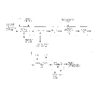
BRIEF DESCRIPTION OF THE DRAWINGS
[0007] Figure 1 is a schematic illustration of one embodiment of the
cyanide recovery
process of the present invention.
[0008] Figure 2 is a schematic illustration showing an application of the
cyanide recovery
process of the present invention where the cyanide recovery process is
employed in the mining
industry.
DESCRIPTION OF EXEMPLARY EMBODIMENTS
[0009] The present invention relates to a method of recovering cyanide from
an aqueous
solution. Generally, the processes disclosed herein entail a pre-treatment
process for removing
metals and oxyanions. This is followed by treating the aqueous solution with
ultraviolet light
which results in the photodissociation of various metal-cyanide complexes and
forming free
cyanide. The free cyanide is converted to volatile hydrocyanic acid by
adjusting the pH of the
aqueous solution down to about 6.0 ¨ 6.5. After pH adjustment, the aqueous
solution including
the hydrocyanic acid is directed to a gas-filled membrane. The hydrocyanic
acid in the aqueous
solution diffuses through the pores of the membrane and is absorbed in a
sodium hydroxide
solution in the stripping side of the gas-filled membrane. This produces
sodium cyanide and
effectively provides a means of recovering the cyanide from the aqueous
solution. The
following description explains these individual processes and the total
process in more detail.
[0010] In many cases, the cyanide-containing aqueous solution will have a
relatively high
pH. This is true for a cyanidation process where the optimum pH is about 10.0
to about 10.5.
Thus, in these cases, one anticipates that most of the metals will already be
precipitated in the
aqueous solution. To assure removal of remaining dissolved metals, the aqueous
solution is
treated such that the metals are removed through precipitation and/or a co-
precipitation/adsorption process. This is achieved, in one embodiment, by
pumping the
aqueous solution into a mixing reactor such as the TURBOMIX reactor that is
marketed by
3
CA 02941223 2016-09-08
Veolia Water Technologies, Inc. See Figure 1 and block 10. To precipitate
metal ions, various
alkali sources such as a caustic (NaOH), hydrated lime (Ca(OH)2), quick lime
(CaO) or
magnesium hydroxide (Mg(OH)2) can be used. Under these conditions, free
cyanide ions will
exist as highly soluble cyanide ions. This means that the risk of
volatilization of hydrocyanic
acid gas (HCN) from the mixing reactor is minimized. However, in a preferred
design, the
mixing reactor is covered but provided with a vent. In some cases, the aqueous
solution may
include significant hardness in the form of calcium and magnesium, for
example. In these
cases, the hardness should be removed in order to prevent carbonate and
sulfate scaling of
downstream equipment, particularly downstream membranes.
[0011] In one embodiment in this pre-treatment process, lime is added and
mixed with the
aqueous solution. See Figure 1. This results in the precipitation of remaining
metals and in the
precipitation of hardness compounds. Some cases will not require the addition
of a ferric ion
because the aqueous solution (such as a spent barren solution resulting from a
cyanidation
process) contains adequate ferric ions in the form of ferric hydroxide. In any
event, ferric ions
function as a coagulant to destabilize solids and, therefore, facilitate their
removal through
precipitation. If required, ferric chloride can be added to co-precipitate and
adsorb the low
concentration of oxyanions in the aqueous solution.
[0012] As a part of pre-treatment, the precipitants and suspended solids
are removed from
the aqueous solution. This can be achieved through clarification. A clarifier
12 can form an
integral part of the TURBOMIX mixing reactor or the clarifier can be disposed
downstream
from the mixing reactor 10 as shown in Figure 1. In any event, the
precipitants and suspended
solids are settled to form sludge or a concentrated waste stream. In one
embodiment, a portion
of the sludge is recycled back to the mixing reactor 10 while a portion of the
sludge is disposed
of through conventional means or subjected to further treatment..
[0013] After clarification, the aqueous solution can be filtered to remove
residual precipitants
and suspended solids. In the embodiment illustrated herein, a multimedia
filter 14 is employed.
4
CA 02941223 2016-09-08
At this point in the process, substantial precipitants and suspended solids
have been removed
from the aqueous solution. But there remains some free cyanide as well as
metal-cyanide
complexes such as copper, zinc and nickel cyanide in the aqueous solution.
[0014] To address the metal-cyanide complexes, the present process
envisions subjecting
the aqueous solution to ultraviolet (UV) light in a UV irradiation unit 16.
The pH of the aqueous
solution is at a relatively high pH, greater than 8.0 and typically in the
range of 10.0-10.5. UV
lights are provided with shrouds or sleeves and submerged in the aqueous
solution. The
shrouds or sleeves surround the UV lights and may have a tendency to foul due
to the relatively
high pH (pH of 10.0-10.5) of the aqueous solution. In order to protect against
fouling of the
shrouds or sleeves, a sequestering agent or anti-scalant can be added to the
aqueous solution
to maintain metal hydroxides in solution.
[0015] UV light, having a wave length in the region from 200 to 350 nm,
causes the metal-
cyanide complexes in the aqueous solution to undergo photodissociation. The
free cyanide ions
in the aqueous solution do not respond to ultraviolet light. However, some of
the weak acid
dissociables (WAD) cyanides and strong acid cyanide complexes, particularly
the ferric and
ferrous hexacyanide complexes, respond well during the photolysis reaction
that takes place
according to the following mechanism:
Fe (CN)63- + 3 H20 + hQ = 6CN- + Fe(OH)3 + 3H+
[0016] Optimum pH for photodissociation of metal-cyanide complexes is 10.0-
10.5. In the
presence of UV light, the metal-cyanide complexes generate free cyanide and
metal hydroxides.
In some cases, it may be desirable to filter the aqueous solution after it has
been subjected to
UV light irradiation. Thus, as an option, a filter 18, such as a cartridge
filter, can be employed to
further filter the aqueous solution downstream of UV light treatment. The
cartridge filter will
remove fine particles of metal hydroxide.
[0017] Now the process turns to removing the free cyanide from the aqueous
solution. To
achieve this, the process aims to convert the free cyanide to hydrocyanic acid
gas. In order to
CA 02941223 2016-09-08
do this, the pH of the aqueous solution must be adjusted downwardly by the
addition of an acid.
To make the conversion, the aqueous solution primarily containing the free
cyanide is directed
to a leak proof covered tank 20 where the pH is adjusted downwardly. In one
embodiment, the
pH is adjusted downwardly to approximately 6.0 to 6.5. This causes the free
cyanide in the
aqueous solution to form the hydrocyanic acid gas.
[0018] Now the process turns to recovering cyanide from the hydrocyanic
acid gas. This is
achieved by employing a gas-filled membrane 22 and a stripping solution that
in one
embodiment is sodium hydroxide. It should be noted that for health and safety
concerns the
aqueous solution containing the hydrocyanic acid gas should be stored or held
relatively close
to the gas-filled membrane 22. A gas-filled membrane is a hydrophobic
microporous membrane
in which the pores are filled with a gas such as air. The gas-filled membrane
is especially suited
to separating and recovering volatile substances, including hydrocyanic acid
gas. When the
gas-filled membrane 22 is disposed between the aqueous solution containing
hydrocyanic acid
vapor and the chemical stripping solution (sodium hydroxide), water is
repulsed and gas (air)
remains in the membrane pores. In the case of hydrocyanic acid gas, it
diffuses through the
boundary layer from the bulk of the feed to the feed-membrane interface. The
hydrocyanic acid
evaporates at the feed-membrane interface and diffuses through the air in the
membrane pores
and moves from the feed side of the membrane to the stripping side. In the
example discussed
herein, the stripping solution is sodium hydroxide. The hydrocyanic acid gas
is absorbed by the
sodium hydroxide and instantaneously reacts with the sodium hydroxide at the
membrane-
stripping interface forming sodium cyanide. Thus, cyanide is recovered from
the aqueous
solution and the recovery is in the form of sodium cyanide which can be used,
as discussed
below, in a number of industrial processes, including the extraction of gold
or silver, as well as
other metals.
[0019] The process just described is shown schematically in Figure 1. The
process
described therein is suitable for a variety of cyanide containing aqueous
solutions where it is
6
CA 02941223 2016-09-08
desirable to recover cyanide. There are many applications for the general
process shown in
Figure 1.
[0020]
Figure 2 shows a particular application of the process shown in Figure 1. The
Figure
2 process depicts a system and process for leaching gold and silver from ore
through a
cyanidation process and thereafter recovering cyanide from a spent barren
cyanidation solution.
As used herein, the term "barren solution" means any aqueous solution. As
shown
schematically in Figure 2, ore containing gold and/or silver is crushed and
sized in a crushing
and sizing unit 24. Thereafter, a slurry is formed by adding water to the
crushed ore. The slurry
containing the crushed ore containing gold and/or silver is directed to a
leaching tank 28. Tank
28 includes a cyanidation solution that is typically sodium cyanide. The
sodium cyanide solution
causes the gold and silver to leach out of the ore into the sodium cyanide
solution. The slurry
from the leaching tank 28 is directed to a zinc precipitation unit 30. In the
example illustrated
herein, zinc dust is mixed with the slurry, causing gold and silver to
precipitate in the zinc
precipitation tank 30. From the zinc precipitation tank 30, the slurry
including the precipitated
gold and silver is directed to a filter 32 where the gold and silver are
separated from the slurry.
The effluent from the filter 32 is the barren solution or a spent barren
solution and contains
sodium cyanide. This barren solution containing sodium cyanide is recycled to
the leaching
tank 28 for further use in leaching gold and silver from the ore slurry.
However, a portion of the
spent barren solution must be wasted or, in the case of the present invention,
subjected to the
recovery of cyanide. This is because the barren solution becomes contaminated
with metals
and oxyanions and other contaminants that cause the sodium cyanide solution to
be ineffective
for leaching purposes. Therefore, the present invention purges a portion of
the barren solution
being recycled to the leaching tank 28 and directs that barren solution
through the process
shown in Figure 1 and described above. The process described in Figure 1 need
not be
repeated in detail. Suffice it to say that the barren solution blowdown shown
in Figure 2 is
subjected to a pre-treatment process for removing metals and thereafter the
barren solution is
7
CA 02941223 2016-09-08
subjected to the UV photodissociation process that produces free cyanide. By
adjusting the pH
of the barren solution after the UV light irradiation treatment, free cyanide
is converted to volatile
hydrocyanic acid in the pH adjustment tank 20 and thereafter the hydrocyanic
acid is absorbed
by a sodium hydroxide stripping solution in the gas-filled membrane 22. The
absorption of the
hydrocyanic acid into the sodium hydroxide solution forms sodium cyanide that
can be recycled
back to the leaching tank 28.
[0021] Thus, the present process is an efficient method of recovering
cyanide and is
particularly useful in the mining industry where cyanide is used for leaching
gold and silver, and
other metals from ores. The combination of pre-treatment, ultraviolet light
photodissociation and
cyanide recovery in a gas-filled membrane makes the overall process safe,
compact and cost
effective.
[0022] The present invention may, of course, be carried out in other ways
than those
specifically set forth herein without departing from essential characteristics
of the invention. The
present embodiments are to be considered in all respects as illustrative and
not restrictive, and
all changes coming within the meaning and equivalency range of the appended
claims are
intended to be embraced therein.
8