Sélection de la langue

Search

Sommaire du brevet 2941467 

Énoncé de désistement de responsabilité concernant l'information provenant de tiers

Une partie des informations de ce site Web a été fournie par des sources externes. Le gouvernement du Canada n'assume aucune responsabilité concernant la précision, l'actualité ou la fiabilité des informations fournies par les sources externes. Les utilisateurs qui désirent employer cette information devraient consulter directement la source des informations. Le contenu fourni par les sources externes n'est pas assujetti aux exigences sur les langues officielles, la protection des renseignements personnels et l'accessibilité.

Disponibilité de l'Abrégé et des Revendications

L'apparition de différences dans le texte et l'image des Revendications et de l'Abrégé dépend du moment auquel le document est publié. Les textes des Revendications et de l'Abrégé sont affichés :

  • lorsque la demande peut être examinée par le public;
  • lorsque le brevet est émis (délivrance).
(12) Demande de brevet: (11) CA 2941467
(54) Titre français: ANNEAU DE ROULEAU AGRICOLE ET CULTITASSEUR COMPRENANT UN ENSEMBLE DE CES ANNEAUX DE ROULEAU AGRICOLE
(54) Titre anglais: AN AGRICULTURAL ROLLER RING AND A LAND PACKER COMPRISING A SET OF SUCH AGRICULTURAL ROLLER RINGS
Statut: Réputée abandonnée et au-delà du délai pour le rétablissement - en attente de la réponse à l’avis de communication rejetée
Données bibliographiques
Abrégés

Abrégé français

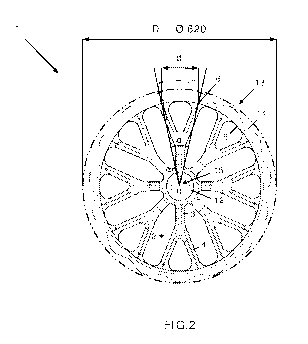
L'invention concerne un anneau de rouleau agricole (1) permettant de tasser le sol tout en enfonçant des pierres rencontrées dans le sol, l'anneau (1) comprenant une partie moyeu (12) avec un trou central (15) permettant de recevoir un arbre (9), une partie jante (13) avec une surface extérieure (14) permettant de tasser le sol, une pluralité de rayons (2), chaque rayon (2) ayant un corps (3) reliant la partie moyeu (12) et la partie jante (13), le corps (3), dans une direction vers la partie jante (13), étant ramifié en une pluralité de bras (4) raccordant le corps (3) à une surface intérieure (5) de la partie jante (13). De plus, l'invention concerne un cultitasseur (7) comprenant un ensemble (8) d'anneaux de rouleau agricole (1) tels que décrits ci-dessus, les anneaux de rouleau agricole (1) étant montés de façon à pouvoir tourner autour d'un arbre central commun (9) monté sur un châssis (11) du cultitasseur (7).


Abrégé anglais

The invention relates to agricultural roller ring (1) for packing the soil while pressing encountered stones in the soil, which ring (1) comprises a hub part (12) with a central hole (15) for receiving a shaft (9), a rim part (13) with an outer surface (14) for packing the soil, a plurality of spokes (2), each spoke (2) having a body (3) connecting the hub part (12) and the rim part (13), wherein the body (3), in a direction towards the rim part (13), is branched into in a plurality of arms (4) connecting the body (3) to an inner surface (5) of the rim part (13). Also, the invention relates to a land packer (7) comprising a set (8) of agricultural roller rings (1) as described above, wherein the agricultural roller rings (1) are mounted rotatably about a common central shaft (9) mounted on a frame (11) of the land packer (7).

Revendications

Note : Les revendications sont présentées dans la langue officielle dans laquelle elles ont été soumises.


5
CLAIMS
1. An agricultural roller ring (1) for packing the soil while pressing
encountered stones
in the soil, which ring (1) comprises a hub part (12) with a central bole (15)
for receiv-
ing a shaft (9), a rim part (13) with an outer surface (14) for packing the
soil, a plurali-
ty of spokes (2), each spoke (2) having a body (3) connecting the hub part
(12) and the
rim part (13), characterized in that the body (3), in a direction towards the
rim part
(13), is branched into a plurality of arms (4) connecting the body (3) to an
inner sur-
face (5) of the rim part (13).
2. An agricultural roller ring (1) according to claim 1, characterized in that
the body
(3) is branched into two arms (4).
3. An agricultural roller ring (1) according to claim 1 or claim 2,
characterized in
that each spoke (2) is Y-shaped.
4. An agricultural roller ring (1) according to claim 2 or 3, characterized in
that each
of the two arms (4) is attached to the inner surface (5) of the rim part at an
attachment
point (6), wherein an angle (a) between the two attachment points (6) ranges
from 23
degrees to 28 degrees.
5. An agricultural roller ring (1) according to any of the preceding claims,
character-
ized in that the number of spokes (2) ranges from 2 to 10 spokes (2).
6. A land packer (7), characterized in that said land packer (7) comprises a
set (8) of
agricultural roller rings (1) according to any of the preceding claims,
wherein the agri-
cultural roller rings (1) are mounted rotatably about a common central shaft
(9)
mounted on a frame (11) of the land packer (7).

Description

Note : Les descriptions sont présentées dans la langue officielle dans laquelle elles ont été soumises.


CA 02941467 2016-09-01
WO 2015/131901 PCT/D K2014/050326
An agricultural roller ring and a land packer comprising a set of such agricul-
tural roller rings
Field of the invention
The invention relates to an agricultural roller ring for packing the soil
while pressing
encountered stones in the soil, which ring comprises a hub part with a central
hole for
receiving a shaft, a rim part with an outer surface for packing the soil, a
plurality of
spokes, each spoke having a body connecting the hub part and the rim part.
Also, the
invention relates to a land packer.
Background of the invention
Typically, a plurality of roller rings sits on a shaft of a land packer
driving on a field.
A roller ring such as the one shown in FIG.1 is used for packing the soil
while press-
ing encountered stones in the soil, thus avoiding that stones get into, e.g.,
a harvester
when the latter is in operation. Basically, when a stone hits the ring, the
ring drives on
it and pushes it in the soil. However, such a roller ring has a short lifetime
as the at-
tachment points of the spokes at the ring tend to crack due to the frequency
of the im-
pacts with the stones. In order to make the ring more durable, reinforcements
may be
applied at the attachment points; nevertheless, this implies an increased
weight and
manufacturing cost for the whole construction.
Hence, there is a need in the technical field of agricultural roller rings and
land packers
of overcoming the abovementioned drawbacks of the state-of-the-art solutions.
Aspects of the invention
The first aspect of the invention is to provide an improvement to the state-of-
the-art.
The second aspect of the invention is to solve the abovementioned drawbacks of
the
prior art, i.e., that of providing an agricultural roller ring that is
stronger and thereby
has a longer lifetime than a conventional roller ring (ref. FIG.!) and a
reinforced ver-
sion of a conventional roller ring. At the same time, the aim of the invention
is to pro-
vide a roller ring that is lighter and thereby less costly to manufacture than
a reinforced
version of a conventional roller ring.

CA 02941467 2016-09-01
WO 2015/131901 PCT/D K2014/050326
Description of the invention
The aforementioned aspects of the invention are achieved by an agricultural
roller ring
as described in the preamble of claim 1, wherein the body, in a direction
towards the
rim part, is branched into a plurality of arms connecting the body to an inner
surface of
the rim part.
Herein, a spoke is defined as an elongated element extending from the center
of the
roller ring (i.e., the hub where the shaft of a land packer is mounted),
connecting the
center of the roller ring with an inner surface of the roller ring.
The invention has the advantage that the impact of the hit of a stone on the
roller ring
is distributed on the arms of a spoke. As a consequence, the roller ring of
the invention
is around 5-7 times stronger than a conventional roller ring and around 3
times strong-
er than a reinforced version of a conventional roller ring. At the same time,
the roller
ring of the invention is around 3 kg lighter than a reinforced version of a
conventional
roller ring. The above assessments have been made comparing roller rings
having the
same diameter.
In an embodiment of the invention, the body is branched into two arms. In
another
embodiment of the invention, each spoke is Y-shaped. Nevertheless, the two
arms of
the spoke may form an arch instead of extending in a diverging, straight
manner from
the body of the spoke. These embodiments have the advantage that the number of
arms is minimized, thus minimizing the complexity and the cost of
manufacturing the
roller ring while still achieving the abovementioned technical effects in
terms of
strength and weight.
In an embodiment of the invention, each of the two arms is attached to the
inner sur-
face of the ring at an attachment point, wherein an angle between the two
attachment
points ranges from 23 degrees to 28 degrees (e.g., 27 degrees in case of 0 500
and 24
degrees in case of 0 620). Correspondingly, the distance between the two
attachment
points ranges between 80 mm to 120 mm (e.g., 96 mm in case of 0 500 and 117 mm
in case of 0 620). Advantageously, said angle and said distance between the
two at-
tachment points increase with the diameter of the ring but, at the same time,
are nar-

CA 02941467 2016-09-01
WO 2015/131901 PCT/D K2014/050326
3
row enough to avoid cracks at the attachment points. This embodiment has the
ad-
vantage that each spoke has a significantly stronger resistance to cracking.
In an embodiment of the invention, the number of spokes ranges from 2 to 10
spokes.
Advantageously, the number of spokes increases with the diameter of the ring
(e.g., 6
spokes in case of 0 500 and 8 spokes in case of 0 620). This embodiment has
the ad-
vantage that the same strength is achieved regardless the diameter of the
ring.
Also, the aforementioned aspects of the invention are achieved by a land
packer com-
prising a set of agricultural roller rings (i.e., at least one set with at
least two roller
rings) according to any of the preceding embodiments, wherein the agricultural
roller
rings are mounted rotatably about a common central shaft mounted on a frame of
the
land packer.
Note that all the aforementioned advantages of the agricultural roller ring
are also met
by the land packer.
Hereafter, the invention will be described in connection with drawings
illustrating
non-limiting examples of agricultural roller rings and land packers.
Brief description of the drawings
FIG.!: PRIOR ART.
FIG.2: A roller ring with Y-shaped spokes.
FIG.3: A land packer with a plurality of sets of roller rings according to the
invention.
Notations
a: angle between two attachment points of the same spoke.
c: center of the roller ring.
d: distance between two attachment points of the same spoke.
D: diameter of the roller ring.
1: roller ring.
2: spoke.
3: body of a spoke.
4: arm of a spoke.

CA 02941467 2016-09-01
WO 2015/131901 PCT/D K2014/050326
4
5: inner surface of the rim part.
6: attachment point.
7: land packer.
8: set of roller rings.
9: shaft.
10: bracket.
11: frame.
12: hub part.
13: rim part.
14: outer surface of the rim part.
15: central hole of the hub part.
Preferred embodiments of the invention
FIG.1 shows an agricultural roller ring 1 according to the prior art. The
roller ring 1
comprises: a hub part 12 with a central hole 15 for receiving a shaft 9 (not
shown in
FIG.!); a rim part 13 with an outer surface 14 for packing the soil; and four
spokes 2,
each spoke 2 having a body 3 connecting the hub part 12 and the rim part 13 at
an at-
tachment point 6 at an inner surface 5 of the rim part 13.
FIG.2 shows an agricultural roller ring 1 according to the invention. The
roller ring 1
comprises a hub part 12 with a central hole 15 for receiving a shaft 9 (ref.
FIG.3), a
rim part 13 with an outer surface 14 for packing the soil and eight spokes 2.
Each
spoke 2 is Y-shaped; in fact, each spoke 2 has a body 3 connecting the hub
part 12 and
the rim part 13, wherein the body 3, in a direction towards the rim part 13,
is branched
into a plurality of arms 4 connecting the body 3 to an inner surface 5 of the
rim part
13. Each of the two arms 4 is attached to the inner surface 5 of the ring 1 at
an attach-
ment point 6, wherein the angle a and the distance d between the two
attachment
points 6 are respectively 24 degrees and 117 mm.
FIG.3 shows a land packer 7 comprising a plurality of sets 8 of agricultural
roller rings
1 as described above, wherein the roller rings 1 in each set 8 are mounted
rotatably
about a common central shaft 9 mounted on a bracket 10 attached to a frame 11
of the
land packer 7. Advantageously, the bracket 10 may also be integral with the
frame 11.

Dessin représentatif
Une figure unique qui représente un dessin illustrant l'invention.
États administratifs

2024-08-01 : Dans le cadre de la transition vers les Brevets de nouvelle génération (BNG), la base de données sur les brevets canadiens (BDBC) contient désormais un Historique d'événement plus détaillé, qui reproduit le Journal des événements de notre nouvelle solution interne.

Veuillez noter que les événements débutant par « Inactive : » se réfèrent à des événements qui ne sont plus utilisés dans notre nouvelle solution interne.

Pour une meilleure compréhension de l'état de la demande ou brevet qui figure sur cette page, la rubrique Mise en garde , et les descriptions de Brevet , Historique d'événement , Taxes périodiques et Historique des paiements devraient être consultées.

Historique d'événement

Description Date
Représentant commun nommé 2020-11-07
Demande non rétablie avant l'échéance 2020-10-15
Inactive : Morte - RE jamais faite 2020-10-15
Représentant commun nommé 2019-10-30
Inactive : Abandon.-RE+surtaxe impayées-Corr envoyée 2019-10-15
Requête pour le changement d'adresse ou de mode de correspondance reçue 2018-01-16
Lettre envoyée 2016-10-20
Inactive : Transfert individuel 2016-10-14
Inactive : Page couverture publiée 2016-09-28
Inactive : Notice - Entrée phase nat. - Pas de RE 2016-09-16
Demande reçue - PCT 2016-09-13
Inactive : CIB attribuée 2016-09-13
Inactive : CIB en 1re position 2016-09-13
Exigences pour l'entrée dans la phase nationale - jugée conforme 2016-09-01
Modification reçue - modification volontaire 2016-09-01
Demande publiée (accessible au public) 2015-09-11

Historique d'abandonnement

Il n'y a pas d'historique d'abandonnement

Taxes périodiques

Le dernier paiement a été reçu le 2019-09-17

Avis : Si le paiement en totalité n'a pas été reçu au plus tard à la date indiquée, une taxe supplémentaire peut être imposée, soit une des taxes suivantes :

  • taxe de rétablissement ;
  • taxe pour paiement en souffrance ; ou
  • taxe additionnelle pour le renversement d'une péremption réputée.

Les taxes sur les brevets sont ajustées au 1er janvier de chaque année. Les montants ci-dessus sont les montants actuels s'ils sont reçus au plus tard le 31 décembre de l'année en cours.
Veuillez vous référer à la page web des taxes sur les brevets de l'OPIC pour voir tous les montants actuels des taxes.

Historique des taxes

Type de taxes Anniversaire Échéance Date payée
TM (demande, 2e anniv.) - générale 02 2016-10-13 2016-09-01
Taxe nationale de base - générale 2016-09-01
Enregistrement d'un document 2016-10-14
TM (demande, 3e anniv.) - générale 03 2017-10-13 2017-09-19
TM (demande, 4e anniv.) - générale 04 2018-10-15 2018-09-28
TM (demande, 5e anniv.) - générale 05 2019-10-15 2019-09-17
Titulaires au dossier

Les titulaires actuels et antérieures au dossier sont affichés en ordre alphabétique.

Titulaires actuels au dossier
DAL-BO A/S
Titulaires antérieures au dossier
AMIT NATHANY
Les propriétaires antérieurs qui ne figurent pas dans la liste des « Propriétaires au dossier » apparaîtront dans d'autres documents au dossier.
Documents

Pour visionner les fichiers sélectionnés, entrer le code reCAPTCHA :


Pour visualiser une image, cliquer sur un lien dans la colonne description du document. Pour télécharger l'image (les images), cliquer l'une ou plusieurs cases à cocher dans la première colonne et ensuite cliquer sur le bouton "Télécharger sélection en format PDF (archive Zip)" ou le bouton "Télécharger sélection (en un fichier PDF fusionné)".

Liste des documents de brevet publiés et non publiés sur la BDBC .

Si vous avez des difficultés à accéder au contenu, veuillez communiquer avec le Centre de services à la clientèle au 1-866-997-1936, ou envoyer un courriel au Centre de service à la clientèle de l'OPIC.


Description du
Document 
Date
(aaaa-mm-jj) 
Nombre de pages   Taille de l'image (Ko) 
Description 2016-08-31 4 266
Dessin représentatif 2016-08-31 1 24
Dessins 2016-08-31 3 291
Abrégé 2016-08-31 1 76
Revendications 2016-08-31 1 56
Avis d'entree dans la phase nationale 2016-09-15 1 195
Courtoisie - Certificat d'enregistrement (document(s) connexe(s)) 2016-10-19 1 102
Rappel - requête d'examen 2019-06-16 1 117
Courtoisie - Lettre d'abandon (requête d'examen) 2019-12-09 1 159
Modification volontaire 2016-08-31 15 513
Rapport prélim. intl. sur la brevetabilité 2016-08-31 13 541
Demande d'entrée en phase nationale 2016-08-31 4 99
Rapport de recherche internationale 2016-08-31 2 53