Note : Les descriptions sont présentées dans la langue officielle dans laquelle elles ont été soumises.
CA 02942789 2016-09-22
282844
ENGINE HAVING VARIABLE PITCH OUTLET GUIDE VANES
FIELD OF THE INVENTION
[0001] The present subject matter relates generally to an aircraft
propulsion device, or
more particularly to an aircraft propulsion device having variable pitch guide
vanes.
BACKGROUND OF THE INVENTION
[0002] A gas turbine engine generally includes a core having, in serial
flow order, a
compressor section, a combustion section, a turbine section, and an exhaust
section.
During operation, an engine airflow is provided to an inlet of the compressor
section
where one or more axial compressors progressively compress the air until it
reaches the
combustion section. Fuel is mixed with the compressed air and burned within
the
combustion section to provide combustion gases. The combustion gases are
routed from
the combustion section to the turbine section. The flow of combustion gasses
through the
combustion section drives the compressor section and is then routed through
the exhaust
section, e.g., to atmosphere.
[0003] In particular configurations, the gas turbine engine additionally
includes a fan
mechanically coupled to the core and a plurality of outlet guide vanes. For
example, the
fan of such a gas turbine engine typically includes a plurality of rotatable
blades driven
by a shaft of the core. Rotation of the plurality of blades generates thrust
for the gas
turbine engine. Additionally, the plurality outlet guide vanes can direct an
airflow from
the blades to, e.g., reduce an amount of noise generated by the gas turbine
engine and
enhance a performance of the gas turbine engine.
[0004] In certain configurations, the gas turbine engine may define an
outer nacelle
enclosing the plurality of fan blades of the fan and the plurality of outlet
guide vanes.
Such a configuration allows for the outlet guide vanes to be rotated about
respective pitch
axes at radially outer ends where the outlet guide vanes attach to the outer
nacelle.
1
CA 02942789 2016-09-22
282844
[0005] However, certain gas turbine engines may not include the outer
nacelle
enclosing the plurality of fan blades and the plurality of outlet guide vanes.
Accordingly,
known means for actuating the outlet guide vanes may not be included with such
gas
turbine engines. Therefore, a gas turbine engine capable of actuating a
plurality of outlet
guide vanes without requiring an outer nacelle enclosing the plurality of
outlet guide
vanes would be useful.
BRIEF DESCRIPTION OF THE INVENTION
[0006] Aspects and advantages of the invention will be set forth in part in
the
following description, or may be obvious from the description, or may be
learned through
practice of the invention.
[0007] In one exemplary embodiment of the present disclosure, an
aeronautical
propulsion device defining a radial direction is provided. The propulsion
device includes
a fan having a plurality of fan blades for providing a flow of air in a
flowpath, as well as a
plurality of variable guide vanes for directing air to or from the fan in a
desired direction.
The plurality of guide vanes each define an inner end and an outer end along
the radial
direction. The plurality of guide vanes are each attached to a housing of the
propulsion
device at the inner end in a rotatable manner the aeronautical propulsion
device
additionally includes a pitch change mechanism positioned within the housing
of the
propulsion device and mechanically coupled to at least one of the plurality of
guide vanes
for changing a pitch of the at least one of the plurality of guide vanes.
[0008] In another exemplary embodiment of the present disclosure, a gas
turbine
engine defining a radial direction is provided. The gas turbine engine
includes a fan
including a plurality of fan blades for providing a flow of air in a flowpath,
and a
plurality of variable outlet guide vanes for directing air from the plurality
of fan blades of
the fan in a desired direction. The plurality of variable outlet guide vanes
each define an
inner end and an outer end along the radial direction. The plurality of
variable outlet
guide vanes are each attached to a core of the gas turbine engine at the inner
end in a
2
CA 02942789 2016-09-22
282844
rotatable manner. The gas turbine engine additionally includes a pitch change
mechanism
positioned within the core of the gas turbine engine and mechanically coupled
to at least
one of the plurality of variable outlet guide vanes for changing a pitch of
the at least one
of the plurality of variable outlet guide vanes.
[0009] These and other features, aspects and advantages of the present
invention will
become better understood with reference to the following description and
appended
claims. The accompanying drawings, which are incorporated in and constitute a
part of
this specification, illustrate embodiments of the invention and, together with
the
description, serve to explain the principles of the invention.
BRIEF DESCRIPTION OF THE DRAWINGS
[0010] A full and enabling disclosure of the present invention, including
the best
mode thereof, directed to one of ordinary skill in the art, is set forth in
the specification,
which makes reference to the appended figures, in which:
[0011] FIG. 1 is a schematic, cross-sectional view of a gas turbine engine
according
to an exemplary embodiment of the present subject matter.
[0012] FIG. 2 is schematic, cross-sectional view of a forward end of a gas
turbine
engine in accordance with another exemplary embodiment of the present subject
matter.
[0013] FIG. 3 is a close-up, cross-sectional view of an attachment
mechanism
attaching a variable guide vane of the exemplary gas turbine engine of FIG. 2
to a core of
the exemplary gas turbine engine of FIG. 2.
[0014] FIG. 4 is a cross-sectional view of an aft engine in accordance with
an
exemplary embodiment of the present disclosure.
3
CA 02942789 2016-09-22
282844
DETAILED DESCRIPTION OF THE INVENTION
[0015] Reference will now be made in detail to present embodiments of the
invention, one or more examples of which are illustrated in the accompanying
drawings.
The detailed description uses numerical and letter designations to refer to
features in the
drawings. Like or similar designations in the drawings and description have
been used to
refer to like or similar parts of the invention. As used herein, the terms
"first", "second",
and "third" may be used interchangeably to distinguish one component from
another and
are not intended to signify location or importance of the individual
components. The
terms "upstream" and "downstream" refer to the relative direction with respect
to fluid
flow in a fluid pathway. For example, "upstream" refers to the direction from
which the
fluid flows, and "downstream" refers to the direction to which the fluid
flows.
[0016] Referring now to the drawings, wherein identical numerals indicate
the same
elements throughout the figures, FIG. 1 is a schematic cross-sectional view of
a gas
turbine engine in accordance with an exemplary embodiment of the present
disclosure.
More particularly, for the embodiment of FIG. 1, the gas turbine engine is a
high-bypass
turbofan jet engine 10, referred to herein as "turbofan engine 10." As shown
in FIG. 1,
the turbofan engine 10 defines an axial direction A (extending parallel to a
longitudinal
centerline 12 provided for reference) and a radial direction R. The turbofan
engine 10
also defines a circumferential direction (not depicted). In general, the
turbofan 10
includes a fan section 14 and a core engine 16, the fan section 14 configured
in
mechanical communication and positioned in flow communication with the core
engine
16.
[0017] The exemplary core engine 16 depicted generally includes a
substantially
tubular outer casing 18 that defines an annular inlet 20. The outer casing 18
encases, in
serial flow relationship, a compressor section including a booster or low
pressure (LP)
compressor 22 and a high pressure (HP) compressor 24; a combustion section 26;
a
turbine section including a high pressure (HP) turbine 28 and a low pressure
(LP) turbine
30; and a jet exhaust nozzle section 32. A high pressure (HP) shaft or spool
34 drivingly
4
CA 02942789 2016-09-22
282844
connects the HP turbine 28 to the HP compressor 24. A low pressure (LP) shaft
or spool
36 drivingly connects the LP turbine 30 to the LP compressor 22.
[0018] Additionally, for the embodiment depicted, the fan section 14
includes a
variable pitch fan 38 having a plurality of fan blades 40 coupled to a disk 42
in a spaced
apart manner. As depicted, the fan blades 40 extend outwardly from the disk 42
generally
along the radial direction R. The fan blades 40 and disk 42 are together
rotatable about
the longitudinal centerline 12 by LP shaft 36 across a power gear box 44. The
power gear
box 44 includes a plurality of gears for adjusting the rotational speed of the
LP shaft 36.
Additionally, the plurality of fan blades 40 are rotatable about respective
pitch axes Pi by
an actuation device (not shown). Moreover, for the embodiment depicted, the
disk 42 of
the variable pitch fan 38 is covered by a rotatable front hub 46
aerodynamically
contoured to promote an airflow through the plurality of fan blades 40.
[0019] Referring still to the exemplary turbofan engine 10 of FIG. 1, the
exemplary
turbofan engine 10 additionally includes a plurality of circumferentially-
spaced outlet
guide vanes 50. The plurality of outlet guide vanes 50 are positioned
downstream from
the fan 38 along the axial direction A and extend outwardly from the outer
casing 18 of
the core engine 16 generally along the radial direction R. Notably, for the
embodiment
depicted, the outlet guide vanes 50 are each rotatable about respective pitch
axes P2 by
one or more actuation devices (not shown), such that the outlet guide vanes 50
may be
referred to as a variable outlet guide vanes. Additionally, the exemplary
turbofan engine
does not include any outer casing enclosing the fan section 14 and/or outlet
guide
vanes 50. Accordingly, for the embodiment depicted, the turbofan engine 10 may
be
referred to as an un-ducted, single fan turbofan engine.
[0020] For the exemplary turbofan engine 10 depicted, the fan section 14,
or more
particularly, the rotation of the fan blades 40 of the fan section 14,
provides a majority of
the propulsive thrust of the turbofan engine 10. Additionally, the plurality
of outlet guide
vanes 50 are provided to increase an efficiency of the fan section 14 as well
as to provide
other benefits, such as, for example, decreasing an amount of noise generated
by the
5
CA 02942789 2016-09-22
282844
turbofan engine 10, by directing a flow of air from the plurality of fan
blades 40 of the
fan section 14.
[0021] During operation of the turbofan engine 10, a volume of air 56
passes over the
plurality of blades 40 of the fan section 14. A first portion of the volume of
air 56, i.e.,
the first portion of air 60, is directed or routed into an engine air flowpath
64 extending
through the compressor section, the combustion section 26, the turbine
section, and the
exhaust section 32. Additionally, a second portion of the volume of air 56,
i.e. a second
portion of air 62, flows around the core engine 16, bypassing the core engine
16 (i.e., in a
bypass air flowpath). The ratio between the second portion of air 62 and the
first portion
of air 60 is commonly known as a bypass ratio.
[0022] Referring still to FIG. 1, the pressure of the first portion of air
60 is increased
as it is routed through the LP compressor 22 and subsequently through the HP
compressor 24. The compressed first portion of air 60 is then provided to the
combustion
section 26, where it is mixed with fuel and burned to provide combustion gases
74. The
combustion gases 74 are routed through the HP turbine 28 where a portion of
thermal
and/or kinetic energy from the combustion gases 74 is extracted via sequential
stages of
HP turbine stator vanes 76 that are coupled to the outer casing 18 and HP
turbine rotor
blades 78 that are coupled to the HP shaft or spool 34, thus causing the HP
shaft or spool
34 to rotate, thereby supporting operation of the HP compressor 24. The
combustion
gases 74 are then routed through the LP turbine 30 where a second portion of
thermal and
kinetic energy is extracted from the combustion gases 74 via sequential stages
of LP
turbine stator vanes 80 that are coupled to the outer casing 18 and LP turbine
rotor blades
82 that are coupled to the LP shaft or spool 36, thus causing the LP shaft or
spool 36 to
rotate, thereby supporting operation of the LP compressor 22 and/or rotation
of the fan
38. The combustion gases 74 are subsequently routed through the jet exhaust
nozzle
section 32 of the core engine 16 to provide propulsive thrust to supplement
propulsive
thrust provided by the fan section 14.
6
CA 02942789 2016-09-22
282844
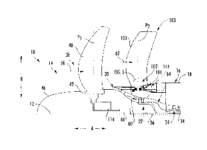
[0023] Referring now to FIG. 2, a close-up, schematic, cross-sectional view
of a
forward end of a gas turbine engine in accordance with an exemplary embodiment
of the
present disclosure is provided. In certain exemplary embodiments, the gas
turbine engine
of FIG. 2 may be configured as a turbofan engine 10 substantially the same as
the
turbofan engine 10 of FIG. 1. Accordingly, the same or similar numbering may
refer to
the same or similar parts.
[0024] As with the exemplary embodiment of FIG. 1, the exemplary turbofan
engine
of FIG. 2 is configured as an un-ducted turbofan engine. As shown, the
turbofan
engine 10 includes a core engine 16 and a fan section 14, the fan section 14
including a
fan 38 having a plurality of fan blades 40 for providing a flow of air. For
the embodiment
depicted, the fan 38 is configured as a variable pitch fan, such that each of
the plurality of
fan blades 40 are rotatable about respective pitch axes Pi by a pitch change
mechanism
90. Additionally, the fan 38 is rotatable about the longitudinal centerline 12
by an LP
shaft 36 of the turbofan engine 10, across a gearbox 44.
[0025] As with the embodiment discussed above, a first portion of the flow
of air 60
provided by the fan 38 flows into an engine air flowpath 64 within the core
engine 16,
wherein such air 60 may be progressively compressed by an LP compressor 22 and
subsequent by an HP compressor 24. A second portion of the flow of air 62
provided by
the fan 38 bypasses the core engine 16 and is provided to a bypass air
flowpath.
[0026] The turbofan engine 10 additionally includes a plurality of variable
guide
vanes 100 for directing air to or from the fan 38 in a desired direction.
Specifically, for
the embodiment depicted, the plurality of variable guide vanes 100 are
configured as a
plurality of variable outlet guide vanes extending generally between a
radially inner end
102 and a radially outer end 103 along the radial direction R. As is depicted,
the plurality
of guide vanes 100 are positioned aft of the plurality of fan blades 40 of the
fan 38, such
that the plurality of guide vanes 100 are configured for directing a flow of
bypass air 62
for the turbofan engine 10.
7
CA 02942789 2016-09-22
282844
[0027] Referring now also to FIG. 3, a close-up, schematic view of a
radially inner
end 102 of an exemplary variable guide vane 100 is provided. The variable
guide vane
100 is attached to a housing of the turbofan engine 10 at the radially inner
end 102 in a
rotatable manner. More particularly, the variable guide vanes 100 is attached
to the core
engine 16 of the turbofan engine 10 at the radially inner end 102 in a
rotatable manner.
[0028] In order to attach the variable guide vane 100 to the core engine 16
in a
rotatable manner, the turbofan engine 10 additionally includes an attachment
mechanism
104 for attaching one or more of the variable outlet guide vanes 100 to the
core engine
16. For the embodiment depicted, the attachment mechanism 104 includes an
inner race
106 attached to a base 108 of the variable guide vane 100 and an outer race
110 attached
to a frame member 112 of the core engine 16. Additionally, a plurality of
bearing
members 113 are provided between the inner and outer races 106, 110 of the
attachment
mechanism 104 to allow for rotation of the variable guide vane 100 about
respective a
pitch axis P2 of the variable guide vane 100. The bearing members 113 may be
configured as any suitable bearing or combination of bearings. For example,
the bearing
members 113 may include one or more cylindrical roller bearings, tapered
roller bearings,
ball bearings, etc. Additionally, it should be appreciated that although a
single guide vane
100 and attachment mechanism 104 is depicted in FIGS. 2 and 3, in certain
embodiments,
each of the plurality of guide vanes 100 may be attached in a rotatable manner
to the core
engine 16 using a corresponding plurality of attachment mechanisms 104. It
should also
be appreciated, however, that the attachment mechanism 104 is provided by way
of
example only, and that in other exemplary embodiments, any other suitable
attachment
mechanisms 104 may be provided.
[0029] Referring still to FIGS. 2 and 3, the turbofan engine 10
additionally includes a
pitch change mechanism 114 positioned within the housing (i.e., positioned
within the
core engine 16) of the turbofan engine 10 and mechanically coupled to at least
one of the
plurality of variable guide vanes 100 for changing a pitch of the at least one
of the
plurality of variable outlet guide vanes 100. For the embodiment depicted, the
pitch
8
CA 02942789 2016-09-22
282844
change mechanism 114 is further mechanically coupled to each of the plurality
of guide
vanes 100 for changing a pitch of each of the plurality of guide vanes 100,
e.g., in unison.
Specifically, for the embodiment depicted, the base 108 of each variable guide
vane 100
includes an extension arm 116 and the pitch change mechanism 114 includes a
rack and
pinion gear system. For example, a rack/ring gear 118 may be attached to each
extension
arm 116 of the plurality of variable guide vanes 100. The pitch change
mechanism 114
may also include one or more pinion gears 120 meshing with the rack/ring gear
118 for
moving the rack/ring gear 118 about a circumferential direction of the
turbofan engine
10, rotating the base 108 of each of the plurality of variable guide vanes
100, which in
turn rotates each of the plurality of variable guide vanes 100 about their
respective pitch
axes P2.
[0030] It should be appreciated, however, that the exemplary turbofan
engine 10
described with reference to FIGS. 2 and 3, including the pitch change
mechanism 114, is
provided by way of example only. In other exemplary embodiments, for example,
any
other suitable pitch change mechanism 114 may be provided. For example, in
other
exemplary embodiments, the pitch change mechanism 114 may be configured for
changing a pitch P2 of one or more of the guide vanes 100 relative to the
remaining guide
vanes 100. More specifically, in certain exemplary embodiments, the pitch
change
mechanism 114 may not be configured for changing a pitch P2 of the plurality
of guide
vanes 100 in unison. For example, in other exemplary embodiments, the pitch
change
mechanism 114 may be configured as one or more swash plates.
[0031] Moreover, in still other exemplary embodiments, any other suitable
gas
turbine engine may be provided, and furthermore, aspects of the present
disclosure may
be utilized with any other suitable aeronautical propulsion device. For
example, referring
now to FIG. 4, a close-up, cross-sectional view is provided of an aft engine
150 in
accordance with an exemplary aspect of the present disclosure. Specifically,
FIG. 4
depicts an exemplary aft engine 150 installed at a tale end of an aircraft
152.
9
CA 02942789 2016-09-22
282844
[0032] Additionally, for the embodiment of FIG. 4, the aft engine 150 is
configured
as a boundary layer ingestion fan, or more particularly, a fan configured to
ingest a
boundary layer flow of air around a fuselage 154 of the aircraft 152 to which
it is
mounted. The exemplary aft engine 150 depicted generally includes a fan 156
rotatable
about a centerline axis 158 of the aft engine 150. The fan 156 generally
includes a
plurality of fan blades 160 attached at an inner end along a radial direction
R2 to a fan
shaft 162 of the fan 156. The fan shaft 162 extends generally along an axial
direction Az
of the aft engine 150 and is mechanically coupled to a power source 164. The
power
source 164 may be an electrical power source, e.g., such as an electric
engine, or
alternatively may be any other suitable power source. For example, in other
embodiments, the power source 164 may include an internal combustion engine or
turbomachinery components positioned at any suitable location.
[0033] The plurality of fan blades 160 of the fan 156 are encircled by a
nacelle 166.
The nacelle 166 extends, for the embodiment depicted, substantially 360
degrees around
a housing or core 168 of the aft engine 150, as well as of a portion of the
fuselage 154 of
the aircraft 152. Accordingly, the nacelle 166 defines an inlet 170 at a
forward end with
the fuselage 154 of the aircraft 152, the inlet 170 extending substantially
360 degrees
around the fuselage 154 of the aircraft 152. For the embodiment depicted, the
nacelle 166
is supported by a plurality of structural members 172 located aft of the
plurality of fan
blades 160. The plurality of structural members 172 may be configured as
outlet guide
vanes.
[0034] Moreover, the aft engine 150 includes a plurality of variable guide
vanes 174
for directing air to the plurality of fan blades 160 in a desired direction.
The plurality of
variable guide vanes 174 are positioned forward of the plurality of fan blades
160 and are
configured as variable inlet guide vanes. Moreover, as is depicted, each of
the plurality of
variable guide vanes 174 are attached to the core 168 of the aft engine 150/
fuselage 154
of the aircraft 152 at a respective radially inner end 176 in a rotatable
manner.
Accordingly, each of the plurality of variable guide vanes 174 are attached in
a
CA 02942789 2016-09-22
282844
cantilevered manner to the core 168 of the aft engine 150/ fuselage 154 of the
aircraft
152. The aft engine 150 additionally includes a pitch change mechanism 178
mechanically coupled to each of the plurality of variable guide vanes 174 for
changing a
pitch P2 of the plurality of variable guide vanes 174, e.g., in unison.
[0035] It should be appreciated, however, that the exemplary aft engine 150
depicted
in FIG. 4 is provided by way of example only, and that in other exemplary
embodiments,
any other suitable aft engine 150 may be provided. For example, in other
exemplary
embodiments, the structural members 172 supporting the nacelle 166 may instead
be
positioned forward of the plurality of fan blades 160, and/or the variable
guide vanes 174
may be positioned aft of the plurality of fan blades 160. Additionally, or
alternatively, the
aft engine 150 may not include the nacelle 166.
[0036] An aeronautical propulsion device including aspects of the present
disclosure
may allow for the variable guide vane to be attached in a cantilevered manner
at a
radially inner end to a housing or core of the propulsion device in a
rotatable manner.
Inclusion of such a variable guide vane may allow for an increased efficiency
of the
propulsion device, as well as providing various other benefits, without
requiring the
propulsion device to include, e.g., a nacelle or other outer casing member
such that the
variable guide vanes may be attached at a radially outer ends thereto and
controlled
therefrom.
[0037] While there have been described herein what are considered to be
preferred
and exemplary embodiments of the present invention, other modifications of
these
embodiments falling within the scope of the invention described herein shall
be apparent
to those skilled in the art.
11