Note : Les descriptions sont présentées dans la langue officielle dans laquelle elles ont été soumises.
AN IMPLANTABLE DUAL SENSOR BIO-PRESSURE TRANSPONDER AND
METHOD OF CALIBRATION
[0001]
FIELD OF INVENTION
[0002] The present general inventive concept relates to systems and
methods of
accurately assessing bodily fluid pressures, such as cerebral spinal fluid
(CSF), and more
particularly, to multiple pressure sensors within a transponder, and the
calibration,
processing, and presentation methods of carrying out the same.
BACKGROUND
[0003] The human body is comprised of various organs that generate, or
are subject to, a
variety of pressures. These pressures are primarily induced externally due to
gravity and
include atmospheric compression and body weight opposition. However, there are
also a
wide range of pressures produced within the body itself These pressures
include those
generated by the cardiovascular system, urinary system, digestive tract,
musculoskeletal
system, central nervous system, osmotic cell pressures, among others. Most of
these
pressures are critical for proper health and must be precisely regulated.
Blood pressure
of the cardiovascular system and cerebral spinal fluid (CSF) of the central
nervous
system are two such components that must be precisely maintained. The ability
to
continuously monitor these pressures would allow for early detection and
intervention in
the event auto-regulation becomes impaired.
1
Date Recue/Date Received 2021-06-14
CA 02943599 2016-09-22
WO 2015/148533 PCT/US2015/022284
[0004] Intracranial pressure is among the most critical found within the
body whereby
intracranial hypotension, resulting in brain matter migration, can lead to
ruptured blood
vessels along the surface of the brain and hematomas while CSF hypertension
can lead to
decreased blood perfusion within the brain. Either case can quickly become
life-
threatening and is estimated to affect one to two percent of the population
congenitally
by hydrocephalus, or acquired due to brain tumor, traumatic obstruction, or
damage to
the arachnoid villi from meningitis, for example.
[0005] Long term monitoring of intracranial pressures (TCP) induced by CSF
is of
particular interest since chronic elevated 'CP is common in patients with
hydrocephalus
and can become life-threatening in acute cases or when shunt treatments fail
or if left
untreated. However, current state of the art monitoring devices require
sensors to be
placed within the brain and tethered to bedside equipment in order to measure
the
pressure. Such measurements typically only allow TCP monitoring for days at a
time,
due to both the required invasiveness and also due to sensor drift, and
require an acute
care clinic setting to facilitate these complicated and risky measurements.
Patient
position becomes critical for accurate measurements by these systems and since
the
sensor is percutaneously tethered from within the brain to a bedside
instrument, the risk
of infection is high. What is needed is a self-contained long-term implantable
bio-
pressure sensor transponder to facilitate recurring and extended in-vivo CSF
pressure
measurement assessments non-invasively, ex-vivo, and which can be routinely
calibrated
for accurate long-term assessment thereby overcoming sensor drift errors and
limitations.
SUMMARY
[0006] A bio-pressure sensor system is disclosed, comprising a first sensor
configured to
provide a reference pressure measurement and second sensor configured to
measure a
fluid pressure within a human body. The bio-pressure sensor system also
comprises a
2
CA 02943599 2016-09-22
WO 2015/148533
PCT/US2015/022284
first reference element and second reference element. The first and second
sensors share
the first reference element. The second reference element is coupled to the
first sensor
and configured to provide a reference pressure. The first and second sensors
each
comprise independent output signals.
[0007] A method for calibration of a bio-pressure sensor implanted in a
patient is also
disclosed herein. The method comprises measuring a first pressure, via a first
pressure
sensor, with the patient in a first position, and measuring a second pressure,
via the first
pressure sensor, with the patient in a second position. The method also
includes
providing a first reference pressure and a second reference pressure, and
calculating a
gain correction, m, based on the first pressure, second pressure, first
reference pressure,
and second reference pressure.
[0008] An additional method for calibration of a bio-pressure sensor
implanted in a
patient is disclosed herein. The method comprises measuring a first pressure,
via a first
pressure sensor, measuring a first environmental pressure coincident with the
first
pressure; measuring a second pressure, via the first pressure sensor;
measuring a second
environmental pressure coincident with the second pressure; and calculating a
gain
correction, m, based on the first pressure, second pressure, first
environmental pressure,
and second environmental pressure.
[0009] Additional systems and methods are described herein.
BRIEF DESCRIPTION OF THE DRAWINGS
[00010] The following embodiments are representative of example techniques and
structures designed to carry out various objectives of the present general
inventive
concept, but those skilled in the art will appreciate that the present general
inventive
concept is not limited to these example embodiments, and that other techniques
and
structures could be chosen with sound engineering judgment to achieve the same
or
3
CA 02943599 2016-09-22
WO 2015/148533 PCT/US2015/022284
similar results as the example embodiments described herein. Moreover, in the
accompanying drawings and illustrations, the sizes and relative sizes, shapes,
and
qualities of lines, entities, and regions may be exaggerated for clarity. A
wide variety of
additional embodiments will be more readily understood and appreciated through
the
following detailed description of the exemplary embodiments, with reference to
the
accompanying drawings in which:
[00011] Fig. lA is a schematic of an example embodiment of the bio-pressure
sensor
system showing subcutaneous implantation of the bio-pressure sensor unit, or
transponder, with a ventricular catheter and reference fluid column.
[00012] Fig. 1B is a schematic of an example embodiment of the bio-pressure
sensor
system showing subcutaneous implantation of the bio-pressure sensor unit, or
transponder, containing multiple sensors and a CSF flow path through the
transponder.
[00013] Fig. 1C is a schematic of an example embodiment of the bio-pressure
sensor
system showing subcutaneous implantation of the bio-pressure sensor unit with
an
intracranial bladder transducer and a reference fluid column.
[00014] Fig. 2 is a schematic illustrating an example dual pressure sensor
unit with an
absolute pressure reference.
[00015] Fig. 3 is a graph illustrating example transfer functions for the two
sensors
embedded into the implantable bio-pressure unit.
[00016] Fig. 4 is a schematic of an example embodiment of the bio-pressure
sensor
apparatus showing a block diagram for electronic signal conditioning and
transcutaneous
non-invasive assessment, or the like.
[00017] Fig. 5 is a schematic of an additional example embodiment of the bio-
pressure
sensor apparatus also showing a block diagram for electronic signal
conditioning and
transcutaneous non-invasive assessment, or the like.
4
CA 02943599 2016-09-22
WO 2015/148533 PCT/US2015/022284
DETAILED DESCRIPTION
[00018] Reference will now be made to example embodiments of the present
general
inventive concept, examples of which are illustrated in the accompanying
drawings and
illustrations. The example embodiments are described herein in order to
explain the
present general inventive concept by referring to the figures.
[00019] Note that spatially relative terms, such as "up," "down," "right,"
"left,"
"beneath," "below," "lower," "above," "upper" and the like, may be used herein
for ease
of description to describe one element or feature's relationship to another
element(s) or
feature(s) as illustrated in the figures. Spatially relative terms are
intended to encompass
different orientations of the device in use or operation in addition to the
orientation
depicted in the figures. For example, if the device in the figures is turned
over or rotated,
elements described as "below" or "beneath" other elements or features would
then be
oriented "above" the other elements or features. Thus, the exemplary term
"below" can
encompass both an orientation of above and below. The device may be otherwise
oriented (rotated 90 degrees or at other orientations) and the spatially
relative descriptors
used herein interpreted accordingly.
[00020] Example embodiments of the present general inventive concept can be
utilized to
realize a recurring non-invasive, real time, in-vivo pressure measurement
transponder,
which can be calibrated and interrogated ex-vivo, such as that which would be
used to
assess CSF pressures in a hydrocephalus patient.
[00021] An implantable pressure sensor system and method of calibration is
provided for
the measurement of fluid pressures within the human body. In one embodiment,
the
system comprises in-vivo dual pressure sensors, whereby one sensor provides a
position
dependent transfer function as a reference signal, the other sensor sensing
the desired
bodily fluid pressure, an amplifier, encoding circuitry, and telemetry unit
allowing
electromagnetic transcutaneous powering, calibration, and interrogation of the
sensor
CA 02943599 2016-09-22
WO 2015/148533 PCT/US2015/022284
system through the use of an ex-vivo telemetric processing module(s) which
calibrates
the implanted pressure sensors against known pressure references and then
accurately
assesses and presents the desired bodily fluid pressure to a user.
[00022] The sensors may be of the piezo-resistive, capacitive, optical
interferometric type,
or other pressure to electrical transduction means, so as to ultimately
provide an
electronic signal proportional to pressure. Such pressure signals may then be
encoded
into a transmission signal whereby the signal may be modulated by amplitude,
frequency,
phase, or temporally such as in the case of pulse width modulation (PWM), in
order to
encode information proportional to the measured pressure signal. One such
method to
encode the pressure sensor signal is to compare an electrical pressure sensor
output to a
predetermined ramp signal, whereby a start to finish signal marker can provide
a
temporally encoded signal that is essentially a pulse width modulated signal.
Alternatively, a particular frequency response may be utilized as a signature
proportional
to pressure whereby an element of the sensor may be combined with an
oscillator to
facilitate a shift in resonance or damping to encode pressure into a carrier
signal. In the
case of a damping modulation, temporal encoding is provided and a receiving
circuit
would measure the exponential or otherwise decay (e.g. PWM) as representative
of a
proportional pressure.
[00023] Precise pressure measurement may be provided by a differential
pressure sensor
with a first absolute pressure reference and by offering substantially
identical or similar
dual pressure sensors, providing individual output signals for each, whereby a
subcutaneous second reference fluid column may be utilized by a first sensor,
which
presents a second reference pressure as a function of position, or other ex-
vivo
controllable means or methods, to produce a known offset for calibration, and
a second
pressure sensor for the determination and measurement of a desired in-vivo
fluid
pressure. Optionally, a means of switching between the second reference
pressure to the
6
CA 02943599 2016-09-22
WO 2015/148533 PCT/US2015/022284
second sensor and the bodily fluid to the first sensor and vice versa may be
incorporated
so as each fluid can selectively stimulate the opposite sensor. Furthermore,
the second
reference pressure may optionally be implemented by means of an
electromagnetic
actuator, providing a predetermined pressure by means of a piston, solenoid,
or any other
volume change mechanism, which can be remotely actuated ex-vivo, for example.
[00024] The powering of the long-term implantable bio-pressure transponder
containing
the sensors may be provided by means of telemetry whereby an inductive or
optical link
can transfer signals of such magnitude as to power or charge the implanted
electronic
circuitry from an external powering device and also to deliver or receive
data. In a
similar means, an inductive, optical, or other electromagnetic method may be
utilized to
send signals proportional-to or encoded-by the measured in-vivo pressures to a
receiver
external to the patient to accomplish non-invasive transcutaneous assessment.
Optionally, such powering and signal transfer may use the same transcutaneous
method
and frequency over a means such as inductive, radio frequency, optical, or
other transfer
means.
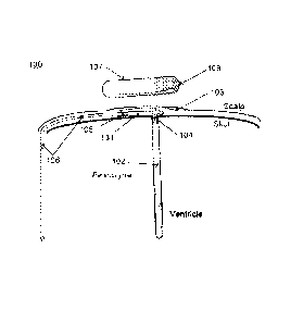
[00025] Fig. lA is an example embodiment of the bio-pressure sensor system
showing
subcutaneous implantation of the bio-pressure sensor unit, or transponder,
containing
multiple sensors, with a ventricular catheter and reference fluid column for
long term
assessment of CSF pressure along with an ex-vivo telemetric processing unit.
[00026] A schematic representation of a subcutaneous bio-pressure sensor
system is
generally indicated by 100. The bio-pressure sensor transponder is located
subcutaneous
and is contained within bio-compatible housing 101 with ICP inlet port 104,
which can
optionally be connected to catheter 102 extending into the brain's ventricle.
Housing 101
may be constructed from, but is not limited to, such biocompatible materials
as titanium,
platinum, ceramic, or glass and may be hermetically sealed by methods
employing, but
not limited to, compressive or reactive glass-to-metal sealing techniques,
ceramic-to-
7
CA 02943599 2016-09-22
WO 2015/148533 PCT/US2015/022284
metal sealing techniques (e.g. employing materials such as alumina, gold,
platinum, ruby,
sapphire, aluminum nitride (A1N), zirconia (ZrO2), silicon carbide (SiC), or
silicon
nitride (Si3N4)), and may further employ any various types of bonding methods,
including active brazing, non-active brazing, or diffusion bonding, and may
also further
utilize anodic bonding for bonding silicon pressure diaphragms, for example,
to a metal
structure, or to housing 101. Other bonding and hermeticity techniques
including
adhesives, including medical grade epoxies, may also be utilized for producing
mechanical integrity and long-term sealing of housing 101. Further, referring
to Fig. 1B,
inlet pressure port, 104, may also optionally allow inlet CSF from catheter
102 to pass-
through the transponder housing, 101, to an integrated exit port, 110, so as
to easily allow
integration with a CSF shunt, such as through tubing 111 while also sensing
the inlet
fluid's pressure.
[00027] However, similar shunt integration may also be accomplished through
the use of a
fluidic tee connector and lumen whereby the transponder element in Fig. lA may
be
connected so as to be in fluid communication with a shunt's existing
ventricular catheter
and shunt system, although such an integration may not offer optimum fluid
dynamics as
in the case of the embodiment illustrated in Fig. 1B. Fig. 1B is another
example
embodiment of the bio-pressure sensor system also showing subcutaneous
implantation
of the bio-pressure sensor unit, or transponder, containing multiple sensors,
but which
contains a CSF flow path through the transponder, of which CSF pressure is
measured,
and in which the transponder also comprises a reference fluid column for long
term
assessment of CSF pressure along with an ex-vivo telemetric processing unit.
[00028] Fig. IC is a schematic of an example embodiment of the bio-pressure
sensor
system also showing subcutaneous implantation of the bio-pressure sensor unit,
or
transponder, containing multiple sensors, but with an intracranial bladder
transducer and
8
CA 02943599 2016-09-22
WO 2015/148533 PCT/US2015/022284
also a reference fluid column for long term assessment of CSF pressure along
with an ex-
vivo telemetric processing unit.
[00029] As shown in Fig. 1C, inlet pressure port may alternatively be
stimulated by an
intracranial pressure bladder, 109, which transduccs ICP via a flexible
membrane to a
fluid contained within 109, in which the bladder's material may be impermeable
to fluids
over long periods of time, relative to a pressure measurement, or of a semi-
impermeable
type flexible material, whereby pores less than 5 p.m may exist, for example.
Furthermore, referring to the illustration in Fig. IC, nothing is to prevent
intracranial
pressure bladder, 109, from being of such length so as to extend into the
brain's ventricle
for reasons of improving ICP measurement which may be desirable for a more
accurate
ICP assessment.
[00030] Reference pressure inlet port 105 is connected to a fluid chamber,
such as a
catheter, or bladder, or fluid column, 106, for atmospheric pressure sensing.
The
pressure presented to inlet port 105 may also be a function of position,
whereby a
predetermined and known fluid pressure is exerted, for example, when
perpendicular to a
gravitational field and then another predetermined and known pressure exerted
when
parallel to a gravitational field for the overall purpose of providing a
variable reference
pressure to the bio-pressure sensor unit for calibration purposes. The
variable reference
pressure may be compared to a known or expected pressure difference based on,
for
example, the geometry of the fluid chamber. Additionally, the reference
pressure may be
compared to a known environmental pressure.
[00031] The reference pressure port 105 may optionally be stimulated by a
different type
of controllable calibrating pressure, such as an electromagnetic piston,
solenoid, or other
volume modulating means, which may be actuated ex-vivo. The reference port 105
may
optionally further utilize atmospheric pressure changes, known by an external
calibrating
apparatus and/or method, in order to utilize a changing pressure, such as that
experienced
9
CA 02943599 2016-09-22
WO 2015/148533 PCT/US2015/022284
by elevation changes, weather patterns, or facility conditions, which may be
exploited for
calibration.
[00032] Telemetry antenna 103 may optionally be located external to housing
101, but yet
connected to the sensor unit, 101, such as through ceramic or glass insulating
seals, and
may be of the inductive, optical, or other electromagnetic type of antenna or
coupling
means for external powering and communications. Transceiver unit, 107, located
ex-
vivo, is used to telemetrically couple to implanted bio-pressure sensor
transponder unit,
101, and to also accurately measure atmospheric pressure through pressure
sensor 108,
which may be calibrated with metrics traceable to a known and accepted
standard, such
as that provided by the National Institute of Standards and Technology, for
example.
[00033] With reference to Fig. 2, there is illustrated and described a dual
pressure sensor
providing an overall differential pressure transducer, generally indicated by
200, with an
absolute pressure reference contained within volume 207 (shown approximately
by the
dashed line). A first pressure port, 201, may accommodate a reference fluid
such as that
described by 105, for example, whereby sensor face 202 gauges such pressure,
and may
be of the piezo-resistive, piezo-electric, capacitive, or optical type, and is
countered by
the reference pressure contained within 207, which may be any pressure from
vacuum or
greater, thereby providing a pressure signal that is indicative of the
pressure difference
from that produced by inlet 201 and reference 207.
[00034] Likewise, second pressure port, 204, may accommodate CSF described by
104,
for example, whereby sensor face 205 gauges such pressure, and may be of the
piezo-
resistive, piezo-electric, capacitive, or optical type, and is countered by
the reference
pressure contained within 207, which, as before, may be any pressure from
vacuum or
greater, thereby providing a pressure signal that is indicative of the
pressure difference
from that produced by inlet 204 and reference 207. In both cases, pressure
sensor faces,
203, and 206 serve to translate the reference pressure and to offset that
presented by
CA 02943599 2016-09-22
WO 2015/148533 PCT/US2015/022284
inlets 201 and 204, respectively, and therefore creates a differential
pressure indication
between the inlets and reference pressure chamber 207.
[00035] Sensors, 202 and 205 are substantially similar or identical in
error characteristics
and also in packaging structure such that error signals induced by stress or
strain in one
sensor is common to the other such that error becomes common-mode. Nothing is
to
prevent however, that sensors may be placed upon or within the surfaces of 203
and 206
or any combination thereof with 202 and 205. In addition, in some embodiments
sensors
202 and 205 may have different error characteristics and packaging structure
relative to
one another. The sensors may be fabricated from silicon or ceramic, for
example, and
from the same die and/or physically located nearby so as to produce similar
characteristics for common-mode rejection capability and may use pressure
transduction
means encompassing any of the piezo-resistive, piezo-electric, capacitive, or
optical
types, or any other prevailing pressure transduction means.
[00036] Fig. 3 illustrates a Cartesian graph, generally denoted 300,
presenting typical
transfer functions for pressure sensors as a function of the input pressure,
P, generating
an electrical output voltage signal vo. The line described by 301 represents a
linear
transfer function, Vi(P), for a pressure sensor that may be used to measure a
reference
input, such as a semi-flexible fluid column aligned vertically within a
patient's torso, as
described by 106. Serving as a positional dependent reference, or otherwise as
previously described, the transfer function for line 106 could be simplified
and described
by:
v1(P) = (P atm P01(0)) = m1(t) b1(t)
where Patm is the atmospheric pressure exerted upon the reference column,
P01(0) is the
positional dependent pressure induced by the reference column/element, mi is
the gain of
11
CA 02943599 2016-09-22
WO 2015/148533
PCT/US2015/022284
the sensor representing the slope of line 301, which is a function of time due
to creep or
other variables, and bi is the zero-pressure of the sensor, represented by the
y-intercept,
303, of line 301, which is also a function of time due to drift caused by
undesirable
changes within the sensor, including but not limited to, changes in the
reference pressure
from volume 207 leaking over time or changes in the structure of the sensor
over time.
[00037] Therefore, once the bio-pressure sensor unit is implanted, mi(t) and
bi(t) become
unknown characteristics. However, the reference pressure, Pc0i(0), described
by 106 is
known, for example, because it presents an a priori column of fluid, or other
means
previously described, with well-understood density and length such that in the
horizontal
patient position, it exerts little to no pressure upon the sensor's 105 input,
but then full
negative pressure in the vertical patient position, and is overall a function
of the patient's
torso incline, 0. In other words, for 0 equal to 0 , the bio-pressure sensor's
reference
input presents only roughly atmospheric pressure, while for 0 equal to 90 ,
the input
receives roughly atmospheric pressure plus a negative pressure equal to the
product of
the fluid column's vertical volume and density and acceleration due to
gravity. In any
case, the function of pressure versus patient position becomes a function of
the reference
column's geometry and routing and may be calculated for various custom in-vivo
implantations.
[00038] In all positions, however, reference column 106 is subject to and
equal to
atmospheric pressure since it may be constructed from a semi-pliable material
compliant
to barometric pressure, but yet stiff enough to resist any bodily influence
upon it and
furthermore, large/long enough such that any localized pressure would not
adversely
affect the average pressure of the column and wherein the column may be open
at one
end such that any localized pinching wouldn't again create noncompliant
pressure to the
barometric average within it. Further, such open distal end of the reference
column may
be located within the peritoneal cavity, without draining by virtue of its
proximal sealed-
12
CA 02943599 2016-09-22
WO 2015/148533 PCT/US2015/022284
end being connected to the sensor input port and since the distal open-end is
within an in-
vivo fluid environment, whereby it is generally expected to track barometric
conditions
on average, but never the less, a change in position of the fluid column also
generates a
change in pressure to the input of the bio-pressure sensor's reference input,
105,
according to its aforementioned properties known a priori.
[00039] Line 305 of Fig. 3 illustrates a typical transfer function of a second
sensor within
the bio-pressure sensor unit that is a function of a second input pressure, P,
which also
generates an output electrical signal, v.. The line described by 305
represents a linear
transfer function, V2(P), for a pressure sensor that may be used to measure a
bodily fluid
input, such as CSF and described by:
V2 (P) = (Patm Põ f (6)) = m2 (t) b2 (t)
where Patm is atmospheric pressure exerted upon the fluid, Pcsf is the
positional dependent
fluid pressure, m2 is the gain of the sensor representing the slope of line
305, which is a
function of time due to creep, and b2 is the zero-pressure of the sensor,
represented by the
y-intercept, 304, of line 305, which is also a function of time due to drift
for the same
reasons described of the first sensor.
[00040] Because the first and second sensors share common characteristics in
packaging
and sensor die, errors are shared between the two sensors as common-mode and
furthermore, since they share the same absolute reference source, 207, their
overall
gain/slope m remains substantially the same, as illustrated by the
representative
interpreting line 302, and reference/offset b also remains substantially the
same between
the sensors such that overall mi(t) = m2(t) and bt(t) = b2(t). in considering
calibrating the
sensors for gain and offset error, since Pc0i(0) presents an a priori known
pressure delta
from upright (i.e. 90 ) to supine (i.e. 0 ), or other such orientations, it
allows the
13
CA 02943599 2016-09-22
WO 2015/148533 PCT/US2015/022284
associated sensor's gain to be determined by taking two transcutaneous
measurements of
the first sensor, Vi(P) over two positions:
vi (90 ) ¨ (0 )
m = (Patat Pc01(90D) (Patm Pc-o4(0 ))
[00041] Note that for differing lengths (i.e. pressure magnitudes) of the
fluid column,
which may vary patient to patient, that both the numerator and denominator
will change
proportionally and not affect the slope or gain determination. It is therefore
unimportant
as to the length (i.e. or pressure delta capability), notwithstanding that a
longer length
(i.e. increased pressure delta capability) may provide an improved noise
immunity, for
determining the gain or slope, m, and that the length and geometry must be
known a
priori to ex-vivo measurements. Note also that a tube of shorter length with a
higher
density fluid may alternatively be used to achieve the same effect as a longer
tube with a
lower density fluid. In the cases described above, it has been assumed that
the fluid
column reference in the supine position is perfectly horizontal and presents
only
atmospheric pressure to its sensor without any negative pressure resulting
from the fluid
column. However, such simplification is for exemplification purposes only.
Variations
in routing of the reference's fluid column would need to be taken into account
for
geometry and 3-D orientation. Furthermore, the overall system may also exploit
known
atmospheric pressure changes, such as that due from elevation changes or
weather
conditions or interior conditions whether intentional or not, to also
determine slope or
gain and calibrate/correct the pressure sensors thereof. It follows that the y-
intercept,
bi(t) = b2(t), can then be determined in the supine position where, Pe0i(0)=0,
according to:
b = v (P atin) (P atm + P441(9)) = m
14
CA 02943599 2016-09-22
WO 2015/148533 PCT/US2015/022284
[00042] Consequently, since the ex-vivo receiving device, 107, can
accurately measure
barometric pressure through sensor, 108, verifiable by means of traceable
calibration,
Patm can be numerically recorded for each determination of b and compared over
the
course of multiple calibrations, wherein any offset/drift error over time can
be tracked
and corrected given the true atmospheric pressure is known, provided linearity
of the
sensors remains true, which is typically adequate in modern pressure sensors.
Now,
given the gain, m, and offset, b, have been determined and corrected for error
relative to
atmospheric pressure, the second sensor, V2(P), can be individually assessed
(i.e. single-
ended) according to:
122 = (Patm Põ f (0)) = in + b
where Pcsf can be accurately determined for a given position. In a
differential mode
assessment, for v2- vi, and for conditions whereby both the first and second
sensors share
atmospheric pressure as common-mode, and whereby hi (t) = b2(t), then
Av = vz¨ vi = (Pcs f (9) P 09)) = m
and the aforedescribed gain correction methods for m enable accurate
differential mode
pressure assessments.
[00043] With reference to Fig. 4, there is illustrated and described
electronic circuitry to
support an example embodiment of an implantable bio-pressure transponder,
generally
referred to by 400. A first pressure sensor, 401, supplies signal proportional
to pressure,
which may be by means of piezo-resistive, capacitive or inductive reactance,
or optical
interferometry, or other transduction means, which is then conditioned by
element 402,
which in this embodiment is an amplifier. 403 describes an encoder for
utilizing the
amplified pressure sensor signal output from element 402 to modulate a
communications
CA 02943599 2016-09-22
WO 2015/148533 PCT/US2015/022284
alternating current (AC.) carrier frequency by means of pulse width
modulation. The
delay element of 403 facilitates settling time of pressure sensor 401 at which
point the
communications oscillator is turned on and the sweep generator of 403 then
begins to
output a ramp signal. The ramp signal is compared to the analog pressure
sensor's
amplifed signal in order to generate a stop signal to the oscillator once the
ramp signal
equates to the analog pressure sensor signal provided through 402. Thus, the
oscillator
output is therefore on for the period of time that the ramp signal doesn't
equate to the
analog pressure sensor signal provided through amplifier 402 and then is off
once the
signals equate. In this way, oscillator output of 403 is proportional in time
relative to the
pressure incident upon 401.
[00044] Element 404 serves as a telemetry unit to facilitate power to the
implanted circuit
as induced from a transceiver external to the sensor and 404 also receives the
encoder's
oscillator circuit output to correspondingly transmit the signal across
communications
element 405, which may optionally be by load shift keying modulation.
Telemetry
transceiver 404 can further accept and encode other pressure sensors, such as
a second
sensor, encoded the same as generally shown in 411 by using alternative
frequencies,
time division multiplexing, or otherwise. Element 405 may be a low and/or high
frequency inductive link, optical transceiver, or other electromagnetic
coupling.
Telemetry transceiver element 406 represents the ex-vivo transceiver which
supplies
power and transmits or receives communication to or from the bio-pressure
transponder.
[00045] Element 407 represents demodulating circuitry to decode pressure
sensor
information from the encoding means received by 406. Element 408 is a pressure
sensor,
which may be traceably calibrated, to provide an accurate barometric pressure
to
microprocessing unit 409 for system formulations and long-term variable
storage.
Finally, element 410 provides the instrument's display unit for human
presentation and
interpretation of the patient's in-vivo pressure, which may optionally be a
remote display.
16
CA 02943599 2016-09-22
WO 2015/148533 PCT/US2015/022284
The example embodiment is representative of one example for implementing the
invention, but does not restrict the variation for which system 411 or 404
stores long-
term variable information, for example, for repeated use by calibrations,
identification
means, or otherwise.
[00046] With reference to Fig. 5, there is additionally illustrated and
described another
example of electronic circuitry to support an example embodiment of the
present general
inventive concept of an implantable bio-pressure transponder, generally
referred to by
500. The dotted lines of Fig. 5 are for illustration purposes only and do not
necessitate or
restrict the example circuitry to any particular enclosing or mechanical means
of
implementation. An implanted biopressure sensor transponder is generally
referred to by
501, an ex-vivo telemetric wireless mobile processing and presentation device
is
generally referred to by 502, and a separate, although optionally integrated
with 502, ex-
vivo telemetric powering device is generally described by 503.
[00047] A plurality of pressure sensors, 502, are amplified and conditioned by
amplifiers
503 which then supply's such signals to the encoding and wireless transceiver
504, which
may optionally be of Bluetooth Low-Energy protocol, in communication with
antenna/coupling-device 505. Antenna/coupling-device 505 telemetrically (i.e.
wirelessly and percutaneously) communicates with antenna/coupling-device 507
of the
ex-vivo processing/receiving device, which supplies such pressure wireless
signals to a
decoder 508, which may optionally be of Bluetooth Low-Energy protocol. The
decoded
signals are then processed by the microprocessor/microcontroller 509 for
applying
various algorithms, including but not limited to pressure sensor
corrections/calibrations
such as gain and offset correction or the application of barometric pressured
measured by
barometer 510, which may optionally be separate from 502. Ex-vivo telemetric
powering device 503 may be comprised of electromagnetic or optical
antenna/coupling-
device 513 which is stimulated by the telemetric power supply 512 optionally
controlled
17
CA 02943599 2016-09-22
WO 2015/148533 PCT/US2015/022284
by 511. The electromagnetic or optical antenna/coupling-device 513 may then be
coupled, wirelessly and percutaneously with in-vivo antenna/coupling device
514 for
wirelessly receiving power by the in-vivo transponder whereby power receiver
506
rectifies and conditions such wireless energy for appropriately powering the
remainder of
the circuitry within 501.
18