Note : Les descriptions sont présentées dans la langue officielle dans laquelle elles ont été soumises.
MONOFLANGE VALVE
Related Applications
This application claims the benefit of U.S. Provisional Application No.
62/237,902 filed October 6, 2015.
Field of Invention
The present invention relates generally to a monoflange valve, and more
particularly to a monoflange valve assembly for use with processing fluids
including severe service media.
Background
Monoflange valves are typically used for pressure instrumentation take-off
points, isolation, sampling, injection, venting, or purging of processing
fluids.
These monoflange valves typically have a valve body with a flange interface
for
mounting directly onto a flanged connection located upstream or downstream of
processing equipment. Known monoflange valves typically have an axial inlet
passage and an outlet passage for communicating the processing fluid from a
main fluid conduit to a pressure gauge or other instrumentation. In addition,
known monoflange valves typically include two or more valve assemblies and
corresponding valve seats disposed within the valve body between the inlet
passage and outlet passage for blocking fluid flow and isolating such
instrumentation, or for venting fluid from the valve body.
Providing multiple valve assemblies within the same monoflange valve
body enables a relatively compact design, and therefore such monoflange valves
are typically used as an alternative to multi-valve systems that require
separate
flange adapters. The more compact monoflange valve design also reduces the
number of potential fluid leakage paths compared to multi-valve designs, which
is useful when such monoflange valves are used in severe service media
applications. When used in severe service applications, the valve assemblies
disposed within the monoflange valve body are often sealingly attached to the
monoflange valve body via welding for preventing the severe service media from
1
Date Recue/Date Received 2022-11-07
CA 02943900 2016-09-30
leaking out of the valve body. To ensure zero defect and leakage from the
welds, the welding interfaces may require 100% weld penetration and 100%
radiographic inspection.
Summary of Invention
Known monoflange valves of the type described above typically have a
configuration in which the valve assemblies are welded at locations that are
too
close to the valve body to allow for automatic weldment processes to generate
consistent and stable welds. The placement of such welded joint connections
close to the valve body also limits the space available for radiographic
examination of the weld. Known monoflange valve designs also typically locate
the valve seats that cooperate with the valve assemblies close to the outer
periphery of the valve body, which increases the length and tortuosity of the
flow
path through the valve body. This reduces the fluid flow characteristics of
known
monoflange designs, and potentially causes the processing fluids to clog in
the
valve body.
According to one aspect, the present invention provides a monoflange
valve assembly having at least one centrally located valve seat that
cooperates
with at least one valve member to open or close a fluid flow path through the
valve body. More particularly, the centrally located valve seat may be located
close to an axial inlet passage to reduce the length and tortuosity of the
flow path
through the valve body, which may enhance fluid flow through the valve body.
In exemplary embodiments, more than one valve seat may be centrally
located in the valve body for cooperating with respective valve members. The
plurality of valve seats may be annularly arranged around the periphery of a
common internal seat pocket chamber to define respective sides of the internal
seat pocket chamber. The internal seat pocket chamber may be fluidly
connected to the axial inlet passage, and the valve seats defining the
respective
sides of the internal seat pocket chamber all may be disposed proximally to
the
axial inlet passage, which may be disposed at a central region of the
monoflange
valve body.
According to another aspect, the present invention provides a monoflange
valve assembly having a main monoflange body with one or more projections
2
CA 02943900 2016-09-30
extending radially outwardly from the main body. One or more valve assemblies
may be welded to the respective projections at locations spaced radially
outwardly from the main valve body. Locating the weldment of the valve
assemblies to the projections away from the valve body in this way may
facilitate
welding and/or inspection of the weldment at the attachment interface. More
particularly, such a configuration may provide sufficient spacing for
automatic
weldment processes to generate a consistent and stable weld (e.g., 100% full
weld penetration), as well as enable sufficient spacing from the main
monoflange
body for improved visual and/or radiographic inspection of the weld (e.g.,
100%
inspection of the weld area).
In exemplary embodiments, the one or more valve assemblies that are
welded to the respective projections may include one or more sealing members,
such as a bellows and a bonnet. The one or more sealing members may be
respectively sealingly attached to each other, to other parts of the valve
assembly, and to the valve body projection so as to reduce or eliminate
leakage
of the processing fluid out of the valve body.
According to an aspect of the invention, a monoflange valve assembly
includes a monoflange body having an axial inlet fluid passage disposed in a
central region of the monoflange body, an outlet fluid passage fluidly
connected
to the axial inlet fluid passage, and an internal bore extending radially
inwardly
from a radially outer periphery of the monoflange body to a valve seat; and a
valve assembly having a valve member disposed in the internal bore, the valve
member having a sealing surface for engaging the valve seat; wherein the valve
member is movable in the internal bore between a closed position in which the
sealing surface engages the valve seat to close a flow path between the inlet
fluid passage and the outlet fluid passage, and an open position in which the
sealing surface disengages from the valve seat to open the flow path between
the inlet fluid passage and the outlet fluid passage; and wherein the valve
seat is
disposed at the central region of the monoflange body between the inlet fluid
passage and the outlet fluid passage to enhance fluid flow through the
monoflange body.
According to another aspect of the invention, a monoflange valve
assembly includes a monoflange body having an axial inlet fluid passage, an
3
CA 02943900 2016-09-30
outlet fluid passage fluidly connected to the axial inlet fluid passage, and a
plurality of internal bores each extending radially inwardly from a radially
outward
periphery of the monoflange body; and a plurality of valve assemblies each
having a valve member disposed in the respective internal bores, the
respective
valve members each have a sealing surface configured to cooperate with
corresponding valve seats disposed at radially inward end portions of the
respective internal bores; wherein the valve seats are annularly arranged
around
a periphery of a common internal seat pocket chamber and define respective
sides of the internal seat pocket chamber.
According to another aspect of the invention, a monoflange valve
assembly includes a monoflange body having a main body portion, the main
body portion having an axial fluid passage for communication with a fluid
stream;
a projection extending radially outwardly from the main body portion, the
projection having an internal bore that extends radially inwardly through the
projection and connects with the axial fluid passage of the main body portion;
and a valve assembly having an attachment body welded to the projection at a
location spaced radially outwardly from the main body portion, thereby
facilitating
welding and/or inspection of the weldment.
The following description and the annexed drawings set forth certain
illustrative embodiments of the invention. These embodiments are indicative,
however, of but a few of the various ways in which the principles of the
invention
may be employed. Other objects, advantages and novel features according to
aspects of the invention will become apparent from the following detailed
description when considered in conjunction with the drawings.
Brief Description of the Drawings
The annexed drawings, which are not necessarily to scale, show various
aspects of the invention.
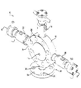
FIG. 1 is a front perspective view of an exemplary monoflange valve
assembly according to an embodiment of the invention.
FIG. 2 is a top view of the monoflange valve assembly in FIG. 1.
FIG. 3 is a rear view of the monoflange valve assembly in FIG. 1 shown
with actuators removed.
4
CA 02943900 2016-09-30
FIG. 4 is a front cross-sectional view of the monoflange valve assembly
taken along the line 4-4 in FIG. 2.
FIG. 5 is a side cross-sectional view of the monoflange valve assembly
taken along the line 5-5 in FIG. 2.
FIG. 6 is a top cross-sectional view of the monoflange valve assembly
taken along the line 6-6 in FIG. 1.
FIG. 7 is an enlarged view of a central region of the monoflange valve
assembly in FIG. 4.
FIG. 8 is an enlarged view of a portion of the monoflange valve assembly
to in FIG. 4.
FIG. 9 is an exemplary computational fluid dynamic simulation of fluid flow
characteristics through the exemplary monoflange valve assembly according to
an embodiment of the invention.
FIG. 10 is an exemplary computational fluid dynamic simulation of fluid
flow characteristics through a prior art monoflange valve assembly.
FIG. 11 is an exemplary simulation of temperature and heat transfer
during welding of a sealing member to an exemplary projection of the exemplary
monoflange valve assembly according to an embodiment of the invention.
FIG. 12 is a cross-sectional view of another exemplary monoflange valve
assembly according to an embodiment of the invention.
FIG. 13 is a side cross-sectional view of the monoflange valve assembly
taken along the line 13-13 in FIG. 12.
FIG. 14 is a cross-sectional view of another exemplary monoflange valve
assembly according to an embodiment of the invention.
FIG. 15 is a side cross-sectional view of the monoflange valve assembly
taken along the line 15-15 in FIG. 14.
Detailed Description
The principles of the present invention have particular application to
monoflange valve assemblies for use with severe service media, such as
Phosgene (C0C12), Chlorine (Cl), Anhydrous Ammonia (NH3), Cyanide (CN),
and/or other severe media, including those from Category M of ASME B31.3,
and thus will be described below chiefly in this context. It is also
understood,
5
CA 02943900 2016-09-30
however, that principles of this invention may be applicable for use in other
applications, including non-severe media applications, where it is desirable
to
enhance fluid flow characteristics during use, or to facilitate welding and/or
inspection of the monoflange valve assembly before use in such applications.
Turning to Figs. 1-3, an exemplary monoflange valve assembly 10 is
shown. The monoflange valve assembly 10 includes a main body portion 12
having an axial inlet fluid passage 14 (shown in Fig. 1), an outlet fluid
passage
16 (shown in Fig. 3), and one or more valve assemblies 18, 20, 22 for enabling
or restricting fluid flow from the inlet fluid passage 14 to the outlet fluid
passage
16.
The main body portion 12 (also referred to as the valve body 12) may
have opposite faces 24, 26 configured to interface directly onto a horizontal
or
vertical flanged connection that stems off of a main fluid conduit line in a
processing stream, which may be upstream or downstream of certain processing
equipment (not shown). In such applications, the inlet fluid passage 14 may be
in fluid communication with the main fluid conduit, and the valve body 12 may
communicate fluid flow via a fluid flow path to the outlet passage 16. The
outlet
passage 16 may be in fluid communication with a pressure gauge, transmitter,
or
other instrumentation for sampling, injecting, isolating, etc. the processing
fluid.
The main body portion 12 also may include bolt holes 28 disposed in an
annular pattern around the face 24 of the valve body 12 for fastening the
monoflange valve body to corresponding flange connection(s), which may
include all standard ANSI classes flange connections. It is understood that
although the monoflange valve body 12 is shown as a generally disc-shaped
body, the valve body 12 may be made into different geometries to accept
different flange-style connections as demanded by the specific application,
which
may include different shapes of the valve body 12 including round,
rectangular,
square, polygonal, or other similar shapes.
In exemplary embodiments, the monoflange valve body 12 may be a
unitary member that may be formed from a unitary metal casting. In the
illustrated embodiment, the monoflange valve assembly 10 also includes a
flange member 30 having a neck 32 extending radially outwardly from the valve
body 12, and a flange 34 disposed at a radially outer portion of the neck 32.
The
6
CA 02943900 2016-09-30
neck 32 may be integral and unitary with the main body portion 12. The flange
34 may have bolt holes 36, and may be configured to interface with a
corresponding flange connection, which may be configured to a standard ANSI
flange connection. As discussed in further detail below, the flange member 30
may have a bleed passage or vent passage for enabling fluid flow to be vented
or bled from the monoflange valve body 12.
Turning to Figs. 4-7, cross-sectional views of the exemplary monoflange
valve assembly 10 are shown. In the illustrated embodiment, the valve body 12
has internal bores 40, 42, 44 extending radially inwardly from a radially
outer
periphery of the valve body 12 to respective valve seats 46, 48, 50, which may
be defined by the valve body or installed in the valve body 12. The valve
assemblies 18, 20, 22 each have a valve member 52, 54, 56 disposed within the
respective internal bores 40, 42, 44. The valve members 52, 54, 56 may include
a valve stem 58, 60, 62 and a sealing surface 59, 61, 63 for engaging the
respective valve seats 46, 48, 50. Each valve stem 58, 60, 62 may be operably
coupled to an actuator 64, 66, 68 for moving the valve stem 58, 60, 62 and
sealing surface 59, 61, 63 toward and away from the respective valve seats 46,
48, 50. In this manner, each valve member 52, 54, 56 is movable in the
internal
bore 40, 42, 44 between a closed position in which the sealing surface 59, 61,
62
engages the valve seat 46, 48, 50 to close a fluid flow path across the valve
seat, and an open position in which the sealing surface 59, 61, 62 disengages
from the valve seat 46, 48, 50 to open a flow path across the valve seat.
For example, as shown in Fig. 4, the first valve assembly 18 has first
valve stem 58 and first sealing surface 59 configured to engage first valve
seat
46 disposed at a radially inward portion of the internal bore 40. The valve
stem
58 may be configured to hold the sealing surface 59, such as a ball, and
carries
the sealing surface 59 toward and away from the valve seat 46 as the valve
stem
58 is moved radially with respect to the valve body 12 in the internal bore
40. As
shown, the valve seat 46 is disposed in the valve body 12 between the axial
inlet
passage 14 and the outlet passage 16 for blocking or allowing fluid flow
through
the monoflange valve body 12.
The actuator 64 is operably coupled to a radially outer portion of the valve
stem 58 and may be operable to move the valve stem 58 radially inwardly or
7
CA 02943900 2016-09-30
outwardly relative to the valve body 12. In the illustrated embodiment, the
actuator 64 includes a handle 69 coupled to a nut 70 having an internal thread
for threadably receiving corresponding outer threads on an upper collar 72
that is
operably coupled to the valve body 12. The actuator 64 also may include a cap
74 and a thrust button 75. As the handle 69 is rotated on the threads inwardly
toward the valve body 12 or outwardly away from the valve body 12, the thrust
button 75 imparts force to move the valve stem 58 radially inwardly or
outwardly
in the internal bore 40 without rotating the valve stem 58 in the bore. Such a
configuration enables non-rotating, linear motion of the valve stem 58 which
may
provide smoother operation for seating or unseating the valve member 52, and
may also facilitate life-cycle testing of the valve assembly with a simple
linear
actuator testing device.
The second valve assembly 20 may be substantially similar to the first
valve assembly 18, and consequently the same reference numerals are used to
refer to the same or similar structures, except where noted. The second valve
assembly 20 has second valve stem 60 and second sealing surface 61
configured to engage second valve seat 48 disposed at a radially inward
portion
of the internal bore 42. The second valve seat 48 is disposed in the valve
body
12 between the axial inlet passage 14 and the outlet passage 16 for blocking
or
allowing fluid flow through the monoflange valve body 12. The second valve
seat 48 is located downstream of the first valve seat 46, and the valve body
12
may have an intermediate passage 76 fluidly connected between the first valve
seat 46 and the second valve seat 48. In this manner, the second valve
assembly 20 cooperating with the second valve seat 48 may provide a
secondary block (or backup) to the first valve assembly 18 (or primary block)
for
blocking fluid flow through the valve body 12.
The third valve assembly 22 may be substantially similar to the first valve
assembly 18 or the second valve assembly 20, and consequently the same
reference numerals are used to refer to the same or similar structures, except
where noted. The third valve assembly 22 has third valve stem 62 and third
sealing surface 63 configured to engage third valve seat 50 disposed at a
radially inward portion of the internal bore 44. The third valve seat 50 is
disposed in the valve body 12 between the axial inlet passage 14 and a bleed
8
CA 02943900 2016-09-30
fluid passage 78. The third valve seat 50 is located downstream of the first
valve
seat 46, and the valve body 12 may have a second intermediate passage 79
fluidly connected between the first valve seat 46 and the third valve seat 50.
In
this manner, the third valve assembly 22 (or bleed valve) may block or allow
fluid
flow to the bleed passage 78 for enabling fluid to be bled or vented from the
monoflange valve body 12. The bleed fluid passage 78 may be fluidly connected
to a bleed outlet 80, and the flange member 30 may include at least a portion
of
the bleed fluid passage 78 and the bleed outlet 80.
It is understood that the although the exemplary monoflange valve
assembly 10 is shown in a double-block and bleed configuration, other
configurations of the monoflange valve assembly 10 may be employed. For
example, the monoflange valve assembly may be configured as a single-block
valve in which only the first valve assembly 18 cooperating with the first
valve
seat 46 is provided. Other configurations of the exemplary monoflange valve
assembly include block and bleed, three-block and bleed, five-block and bleed
and others. In addition, although the exemplary monoflange valve assembly 10
is shown having sealing surface 59, 61, 63 configured as a ball, other types
of
sealing surfaces and corresponding valve seats may be employed, including for
example cone, swivel, wafer, hard seat and soft seat style sealing
configurations.
It is further understood that although the internal bores 40, 42, 44 and
various
fluid passages 14, 16, 76, 78, 79 in the monoflange valve body 12 are shown as
straight paths with cylindrical cross-sections, other configurations may be
employed, including for example polygonal cross-sections or non-linear paths,
which may be made or formed by casting, machining, or other such techniques
known in the art.
As shown in Fig. 7, the valve seat 46 that cooperates with the first valve
member 52 may be located at a central region 82 of the main monoflange body
12. More particularly, the valve seat 46 may be located proximal or adjacent
to
the inlet passage 14 which is disposed at the central region 82 of the valve
body
12. As used herein, the term "central region" refers to the region 82 of the
valve
body 12 that is located radially inwardly of an imaginary annulus defined by
radially inner sides of the bolt holes 18, and both the inlet passage 14 and
valve
seat 46 may be located in this central region 82. In exemplary embodiments,
9
CA 02943900 2016-09-30
both the inlet passage 14 and the valve seat 46 may be located closer to the
center of the valve body 12 in cross-section than to the radially outer
periphery of
the valve body 12, as shown. By locating the valve seat 46 at the central
region
82 between the centrally located inlet passage 14 and the outlet passage 16,
the
.. axial flow path through the valve body 12 may be shortened and fluid flow
characteristics through the valve body may be enhanced. The shorter flow path
provided by such a configuration also may reduce the tendency of certain
processing fluids (e.g., phosgene) to clog in the valve body 12, which
otherwise
could reduce flow performance. In addition, by locating the valve seat 46 at
the
.. central region 82 of the valve body 12, sufficient thickness around the
valve seat
46 may be provided so as to enable the valve body 12 to withstand higher
operating pressures.
Also as shown in the illustrated embodiment, the second valve seat 48
and/or the third valve seat 50 may be located at the central region 82 of the
.. valve body 12. More particularly, the second valve seat 48 and/or the third
valve
seat 50 may be located closer to the center of the valve body 12 than the
outer
periphery of the valve body 12, or may be located proximally to the centrally
located inlet passage 14.
In exemplary embodiments, the respective valve seats 46, 48, 50 may be
.. annularly arranged around a periphery of a common internal seat pocket
chamber 84 to define respective sides of the internal seat pocket chamber 84.
In
this manner, the respective valve seats 46, 48, 50 all may be centrally
located
proximally to the centrally located inlet passage 14 so as to shorten the flow
paths and enhance fluid flow characteristics. For example, locating the second
.. valve seat 50 at the central region downstream of the first valve seat 48
and
upstream of the outlet passage 16 may enable a shorter flow path and enhance
fluid flow from the inlet passage 14 to the outlet passage 16. Similarly,
locating
the third valve seat 52 at the central region downstream of the first valve
seat 48
and upstream of the bleed passage 78 also may enable improved flow over prior
.. art monoflange valve designs.
Referring to Figs. 9 and 10, a simulation of the fluid flow characteristics
through the exemplary monoflange valve 10 (Fig. 9) compared to a simulation of
the fluid flow characteristics of a conventional monoflange valve 200 (Fig.
10)
CA 02943900 2016-09-30
are shown. As shown in Fig. 10, the conventional monoflange valve 200 has
valve seats 202, 204, and 206 that are located close to the outer periphery of
monoflange valve body 208. That is, the valve seats 202, 204, 206 are located
radially outwardly of an imaginary annulus defined by radially inner sides of
.. radially outer bolt holes 210. In the illustrated simulation, the valve
seats 202,
204, 206 of the conventional monoflange valve 200 correlate to the valve seats
46, 48, and 50, respectively, of the exemplary monoflange valve 10, and the
axial inlet passage 212 is located at the central region of the valve body
208. By
locating the valve seats 202, 204, 206 close to the radially outer periphery
of the
io valve body 208, the flow paths within the valve body are long and
tortuous,
which can reduce fluid flow characteristics and potentially cause clogging of
certain processing fluids in the valve body. For example, as shown in the
illustrated simulation of Fig. 10, the static pressure within intermediate
passages
214, 216 is at a relatively elevated level compared to the static pressure at
the
inlet passage 212. The static pressure at the outlet passage 213 is also
elevated compared to the static pressure at the inlet passage 212 and
intermediate passages 214, 216.
In comparison, Fig. 9 shows an exemplary simulation of the fluid flow
characteristics through the exemplary monoflange valve 10 of the present
invention. As discussed above, the monoflange valve 10 has a main valve body
portion 12 having valve seats 46, 48 located at a central region of the valve
body
12 proximal a centrally located axial inlet passage 14. As shown in the
illustrated simulation, the flow path from the inlet passage 14 to the outlet
passage 16 is relatively short compared to the flow path in the conventional
.. monoflange valve 200 (Fig. 10). In addition, the static pressure in the
seat
pocket chamber 84 and the intermediate passage 76 is relatively low compared
to the static pressure at the inlet passage 14.
The comparative results of such flow simulations indicate that the
exemplary monoflange valve 10 has up to about 70% higher Cv rating (less
pressure drop across the choke under 1 gpm of flow) compared to the Cv rating
of the conventional monoflange valve 200. In addition, the shorter flow path
of
the exemplary monoflange valve 10 may provide for a reduced axial thickness of
11
CA 02943900 2016-09-30
the valve body 12 compared to the conventional design, which may result in the
monoflange valve 10 being up to about 80% lighter than the prior art design.
Referring again to Figs. 4-8, one or more of the valve assemblies 16, 18,
20 of the exemplary monoflange valve 10 may each include an attachment body,
such as a sealing member, which may be used in severe service applications to
reduce the potential for leakage of the processing fluid through the internal
bores
40, 42, 44 to the outside environment.
For example, as shown in Fig. 4 and the enlarged views of Figs. 7 and 8,
the sealing member of each valve assembly 16, 18, 20 may include a bellows 86
that is sealingly attached via welding to a radially inward portion of the
respective
valve stems 58, 60, 62 (shown at welding regions 88). The valve assemblies 18,
20, 22 also may include a bonnet 90 disposed at a radially outward portion of
the
valve body 12. The bellows 86 may have a radially outward portion that is
sealingly attached via welding to the bonnet 90 (shown at welding regions 92).
The bonnet 90 includes a bonnet internal bore 94, and the valve stem 62 may be
movable in the bonnet internal bore relative to the bonnet 90 to allow the
valve
member 56 to open and close the flow path across the valve seat 46, 48, 50, as
discussed above.
The respective valve assemblies 18, 20, 22 may further include a second
seal member, or seal 96, such as a seal packing, which may include a Grafoil
packed-seal, chevron-packed seal, 0-ring packed seal, or other encapsulated
pressure core seal, and which may be disposed within the bonnet internal bore
94 surrounding the valve stem 62. Such a seal 96 may provide a backup seal to
the sealing member provided by the bellows 86 and bonnet 90. A plurality of
seals 96 may be disposed within the bonnet internal bore 94 sandwiched
between respective sealing rings 98. A radially outward packing ring 100 may
cooperate with a bonnet cap 101 and a packing gland 102 to contain the seals
96 in the bonnet internal bore 94, The bonnet cap 101 may be threaded to an
outer portion of the bonnet 90 and fixed in place with set screws. The packing
gland 102 may be operatively coupled to the upper collar 72 of the actuator,
which is operatively coupled to the handle 69 via nut 70.
In exemplary embodiments, the monoflange valve 10 includes one or
more projections 110, 112, 114 that extend radially outwardly from the main
12
CA 02943900 2016-09-30
valve body portion 12. As shown, the one or more projections 110, 112, 114
each correspond with the respective valve assemblies 18, 20, 22, and each
projection 110, 112, 114 includes a radially outward portion of the internal
bore
40, 42, 44 that extends through the valve body 12 to respective valve seats
46,
48, 50. In exemplary embodiments, the respective projections 110, 112, 114 are
integral and unitary with the main valve body portion 12 so as to reduce the
number of leakage paths through the valve body 12.
The bonnets 90 (or other sealing member) maybe sealingly attached to
each of the projections 110, 112, 114 at locations spaced radially outwardly
from
the main valve body portion 12 (e.g., at regions 116 in the illustrated
embodiment). As shown in the illustrated embodiment, the bonnets 90 may be
welded to radially outward and portions of the respective projections 110,
112,
114. The radially outward portion of the bellows 86 is sealingly attached such
as
via welding to the bonnet 90, and the radially inward portion of the bellows
86 is
sealingly attached to the valve stem (e.g., 58, 60, 62). In this manner, the
bellows 86 extending across the internal bore (e.g., 40) from the valve stem
(e.g., 58) to the bonnet 90 may seal the internal bore.
In exemplary embodiments, the bonnets 90 may be coupled to the
projections 110, 112, 114 at locations sufficiently spaced from the valve body
12
to enable an automatic welding process to produce a consistent weld. Each of
the projections 110, 112, 114 have an outer surface and an inner surface,
defining a tubular wall therebetvveen, and the weld process may provide 100%
weld penetration through the projection tubular wall. In an exemplary weld
process, a groove may be cut into the tubular wall of the projection 110, 112,
114, and a first-pass penetration weld attaches the bonnet 90 to the
projection.
A second-pass filler weld may then provide 100% weld penetration through the
full tubular wall thickness of the projection.
Welding the valve assembly attachment body, such as the sealing
member (e.g., bonnet 90), to the respective projections 110, 112, 114 at
locations spaced from the valve body 12 also offers an opportunity for the
weldments to be fully inspected such as by radiographic testing. More
particularly, the projection 110, 112, 114 may space the valve body 12 a
sufficient distance from the weld location such that the mass of the valve
body
13
CA 02943900 2016-09-30
12 does not obstruct the radiographic examination of the weld. In exemplary
embodiments where a 2-inch diameter monoflange body is used, the bonnet 90
or other sealing member may be welded to the projection 110, 112, and 114 at a
distance of about 0.25 inches to about 0.5 inches from the valve body 12.
Providing the projections 110, 112, 114 extending radially outward from
the valve body 12 and welding the bellows 90 or other sealing member at a
location sufficiently spaced from the valve body 12 also may enable improved
heat transfer away from the welded area (heat affected zone). For example,
such a configuration may enable heat transfer from the welding to be more
.. uniform and the heat generated from the weld may be limited to a
temperature
that is less than the annealing point of the bellows or other sealing
material. For
example, Fig. 11 shows an exemplary simulation of temperatures and heat
transfer during an exemplary welding operation in which the bonnet 90 is
welded
to the projection 110 at region 116 on the left side in the illustration. As
shown in
the illustrated simulation, by welding the bonnet 90 to the projection 110 at
the
location 116 spaced from the valve body 12, the peak temperature that reaches
the bellows 86 is less than half the annealing temperature of the bellows
material
temperature.
Turning to Figs. 12 and 13, another exemplary embodiment of a
monoflange valve assembly 310 is shown. The monoflange valve assembly 310
is substantially the same as the above-referenced monoflange valve assembly
10, and consequently the same reference numerals but indexed by 300 are used
to denote structures corresponding to similar structures in the monoflange
valve
assemblies 10, 310. In addition, the foregoing description of the monoflange
valve assembly 10 is equally applicable to the monoflange valve assembly 310
except as noted below. Moreover, it is understood that aspects of the
monoflange valve assemblies 10, 310 may be substituted for one another or
used in conjunction with one another where applicable.
The monoflange valve assembly 310 includes a main monoflange body
312, or valve body, having an axial inlet fluid passage 314 disposed at a
central
region of the monoflange body 312, an outlet fluid passage 316 fluidly
connected
to the axial inlet fluid passage 314, and internal bores 340, 342, 344
extending
radially inwardly from a radially outer periphery of the monoflange body 312
to
14
CA 02943900 2016-09-30
respective valve seats 346, 348, 350. The monoflange valve 310 also includes a
first valve assembly 318 (e.g., primary block), a second valve assembly 320
(e.g., secondary block), and a third valve assembly 322 (e.g., bleed) having
respective valve members disposed in the respective internal bores 340, 342,
344. The valve members include respective valve stems 358, 360, 362 and
sealing surfaces 359, 361, 363 (shown in a ball-type configuration) for
engaging
the respective valve seats 346, 348, 350. The valve assemblies 318, 320, 322
also include respective actuators 364, 366, 368 for moving the respective
valve
stems 358, 360, 362 and sealing surfaces 359, 361, 363 in the respective
lc internal bores between a closed position in which the respective sealing
surfaces
engage the respective valve seats to close a flow path across the valve seats,
and an open position in which the respective sealing surfaces disengage from
the respective valve seats to open the flow path between across the valve
seats.
In comparison to the exemplary monoflange valve assembly 10 which has the
second valve assembly 20 and the third valve assembly 22 arranged at about
90-degrees relative to the first valve assembly 18 (e.g., a "T-shaped"
configuration), the exemplary monoflange valve assembly 310 has the second
valve assembly 320 and the third valve assembly 322 arranged at acute angles
relative to the first valve assembly 318 (e.g., a "W-shaped" configuration).
As shown in the illustrated embodiment in Figs. 12 and 13, the first valve
seat 346 that cooperates with the first valve member 318 is disposed at the
central region of the monoflange body 312 between the inlet fluid passage 314
and the outlet fluid passage 316 to enhance fluid flow through the monoflange
body 312. As shown, the second valve seat 348 is also disposed at the central
region of the monoflange body 312 between the inlet fluid passage 314 and the
outlet fluid passage 316, where the second valve seat 348 is downstream of the
first valve seat 346 via intermediate passage 376. Also as shown, the third
valve
seat 350 is disposed at the central region of the monoflange body 312 between
the inlet passage 314 and bleed passage 378, where the third valve seat 350 is
downstream of the first valve seat 348 via second intermediate passage 379.
The centrally located valve seats 346, 348, 350 may be located proximal the
inlet
passage 314, or may be located closer to the center of the valve body 312 than
a radially outer periphery of the valve body 312, or may be located radially
CA 02943900 2016-09-30
inwardly of an imaginary annuls defined by radially inward edges of bolt holes
318. The monoflange valve 310 may further a flange member having a neck 332
extending radially outwardly from the valve body 312 and a flange 334 disposed
at a radially outward end portion of the neck 332. The neck 332 may be fluidly
connected to the bleed fluid passage 378.
The monoflange valve assembly 310 also may include one or more
projections 410, 412, 414 extending radially outwardly from the main body
portion 312. The respective projections 410, 412, 414 include a radially
outward
portion of the respective internal bores 340, 342, 344, and the respective
valve
u) assemblies 318, 320, 322 may each include an attachment body welded to
the
respective projections 410, 412, 414 at respective locations spaced radially
outwardly from the main body portion 312, thereby facilitating welding and/or
inspection of the weldment. The respective attachment bodies may include one
or more sealing members. For example, the respective valve assemblies 318,
320, 322 may each include a bonnet 390 welded to the projection at locations
spaced radially outwardly from the main body portion 312. A bellows 386 may
be sealingly attached to the bonnet 390 at a radially outward portion of the
bellows, and the bellows 386 may be sealingly attached to the valve stem 358,
360, 362 at a radially inward portion of the bellows 386. Such a configuration
of
the monoflange valve assembly 310 may enable it to reduce or eliminate
leakage of processing fluid out of the valve body 312 for use in severe
service
applications.
Turning to Figs. 14 and 15, another exemplary embodiment of a
monoflange valve assembly 510 is shown. The monoflange valve assembly 510
is similar to the above-referenced monoflange valve assembly 10, and
consequently the same reference numerals but indexed by 500 are used to
denote structures corresponding to similar structures in the monoflange valve
assemblies 10, 510. In addition, the foregoing description of the monoflange
valve assembly 10 is equally applicable to the monoflange valve assembly 510
except as noted below. Moreover, it is understood that aspects of the
monoflange valve assemblies 10, 510 may be substituted for one another or
used in conjunction with one another where applicable.
The monoflange valve assembly 510 includes a main monoflange body
16
CA 02943900 2016-09-30
512, or valve body, having an axial inlet fluid passage 514 disposed at a
central
region of the monoflange body 512, an outlet fluid passage 516 fluidly
connected
to the axial inlet fluid passage 514, and internal bores 540, 542, 544
extending
radially inwardly from a radially outer periphery of the monoflange body 512
to
respective valve seats 546, 548, 550. The monoflange valve 510 also includes a
first valve assembly 518 (e.g., primary block), a second valve assembly 520
(e.g., secondary block), and a third valve assembly 522 (e.g., bleed) having
respective valve members disposed in the respective internal bores 540, 542,
544. The valve members include respective valve stems 558, 560, 562 and
sealing surfaces 559, 561, 563 (shown in a ball-type configuration) for
engaging
the respective valve seats 546, 548, 550. The valve assemblies 518, 520, 522
also include respective actuators 564, 566, 568 for moving the respective
valve
stems 558, 560, 562 and sealing surfaces 559, 561, 563 in the respective
internal bores between a closed position in which the respective sealing
surfaces
engage the respective valve seats to close a flow path across the valve seats,
and an open position in which the respective sealing surfaces disengage from
the respective valve seats to open the flow path between across the valve
seats.
Similar to the monoflange valve assembly 310, the monoflange valve assembly
510 has the second valve assembly 520 and the third valve assembly 522
arranged at acute angles relative to the first valve assembly 518 (e.g., a "W-
shaped" configuration).
As shown in the illustrated embodiment in Figs, 14 and 15, the first valve
seat 546 that cooperates with the first valve member 518 is disposed at the
central region of the monoflange body 512 between the inlet fluid passage 514
and the outlet fluid passage 516 to enhance fluid flow through the monoflange
body 512. As shown, the second valve seat 548 is also disposed at the central
region of the monoflange body 512 between the inlet fluid passage 514 and the
outlet fluid passage 516, where the second valve seat 548 is downstream of the
first valve seat 546 via an intermediate passage. Also as shown, the third
valve
seat 550 is disposed at the central region of the monoflange body 512 between
the inlet passage 514 and a bleed passage 578, where the third valve seat 550
is downstream of the first valve seat 548 via a second intermediate passage.
The centrally located valve seats 546, 548, 550 may be located proximal the
inlet
17
CA 02943900 2016-09-30
passage 514, or may be located closer to the center of the valve body 512 than
a radially outer periphery of the valve body 512, or may be located radially
inwardly of an imaginary annuls defined by radially inward edges of bolt holes
518.
In comparison to the exemplary monoflange valve assemblies 10, 310
which have projections (e.g., 110, 410) extending from the valve bodies 12,
312,
the exemplary monoflange valve assembly 510 does not have such projections.
The respective valve assemblies 518, 520, 522 of the monoflange valve
assembly 510 also do not include a bellows welded to the valve body 512.
to Instead, the respective valve assemblies 518, 520, 522 include regular
valve
packing as sealing members, and may be coupled to the valve body 512, such
as by threading. Such a configuration of the monoflange valve assembly 510
may provide a less expensive alternative to the monoflange valve assemblies
10, 310 for use in non-severe service applications, while still enhancing
fluid flow
characteristics through the valve body by centrally locating the valve seat(s)
and/or shortening the fluid flow path through the valve body.
The exemplary monoflange valve described herein provides a relatively
short flow path through the valve body, which may enhance fluid flow, thereby
reducing problems associated with certain process fluids, for example, to
reduce
the tendency of clogging. More particularly, the exemplary monoflange valve
may have a valve member for cooperating with a valve seat located at or near
the center of the valve body and/or inlet fluid passage for reducing the
length
and/or tortuosity of the flow path. Such a configuration also may provide
sufficient mass around the valve seat to accommodate a valve body with
.. reduced size and weight compared to known monoflange valves.
Such a configuration also may enhance valve performance in a compact
design profile. For example, in exemplary embodiments the valve assembly may
include a sealing member such as a bellows, which may be sealingly attached at
radially inward and outward end portions. The unique length of the
bellows/stem
assembly may offer a greater stroke to fully open a bigger bore, and also may
provide for a choke location adjacent the inlet and outlet of the process
commodity. In this manner, by providing a straight and long passage for the
bellows seal valve assembly, more room may be provided for the bellows seal
18
CA 02943900 2016-09-30
valve assembly to accommodate a larger bore in a more compact design profile,
which reduces the overall size of the exemplary valve and manifold assembly.
As such, the entire bellows/stem assembly can be located in the valve body
radially inwardly of the bolt pattern, which may allow the valve body to
provide
the necessary thickness to withstand high pressures.
The exemplary monoflange valve assembly described herein may include
projections extending radially outwardly from the valve body, which may
provide
enough room for an automatic weldment process to produce a consistent weld
with 100% full penetration of the weldment through the transverse thickness of
the projection at the joint connection. In addition, coupling the bellows seal
valve
assemblies to the projections at such locations spaced from the valve body via
welding also offers an opportunity for the welds to be fully radiographed and
inspected. For example, the valve body may be spaced a sufficient distance
from the weld location such that the mass of the body does not obstruct the
radiographic examination of the weld. In addition, by providing the
projections
and welding the bellows seal valve assemblies at locations sufficiently spaced
from the valve body, heat transfer away from the welded area (heat affected
zone) may be improved. For example, heat transfer may be more uniform and
the heat generated from the weld may be limited to less than the annealing
point
of the bellows material.
Although the invention has been shown and described with respect to a
certain embodiment or embodiments, it is obvious that equivalent alterations
and
modifications will occur to others skilled in the art upon the reading and
understanding of this specification and the annexed drawings. In particular
regard to the various functions performed by the above described elements
(components, assemblies, devices, compositions, etc.), the terms (including a
reference to a "means") used to describe such elements are intended to
correspond, unless otherwise indicated, to any element which performs the
specified function of the described element (i.e., that is functionally
equivalent),
even though not structurally equivalent to the disclosed structure which
performs
the function in the herein illustrated exemplary embodiment or embodiments of
the invention. In addition, while a particular feature of the invention may
have
been described above with respect to only one or more of several illustrated
19
CA 02943900 2016-09-30
embodiments, such feature may be combined with one or more other features of
the other embodiments, as may be desired and advantageous for any given or
particular application.