Note : Les descriptions sont présentées dans la langue officielle dans laquelle elles ont été soumises.
CA 02943960 2016-10-03
GRAIN MASS FLOW RATE DETERMINATION
BACKGROUND
[0001] Determining or estimating grain mass flow rate assists in the
harvesting of
the grain as well as crop management. The determination or estimation of grain
mass
flow rate using cameras has been prone to inaccuracies.
BRIEF DESCRIPTION OF THE DRAWINGS
[0002] Figure 1 is a schematic diagram of an example harvester that
estimates
grain mass flow rate using a camera.
[0003] Figure 2 is a flow diagram of an example method that may be
carried out
by the harvester of Figure 1.
[0004] Figure 3 is a schematic diagram of another example harvester that
estimates grain mass flow rate using a camera.
[0005] Figure 4 is a sectional view of the harvester of Figure 3 take
along line 4-
4.
[0006] Figure 5 is a schematic diagram illustrating grain relaxation or
retraction
caused by rotation of an auger.
[0007] Figure 6 is a flow diagram of an example method that may be
carried out
by harvester 20 or harvester 220 to accommodate such grain relaxation.
[0008] Figure 7 is a schematic diagram of another example harvester that
estimates grain mass flow rate using a camera.
1
CA 02943960 2016-10-03
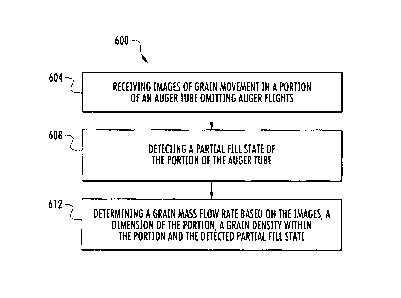
[0009] Figure 8 is a flow diagram of an example method that may be
carried out
by the harvester of Figure 1, the harvester of Figure 3 and/or the harvester
of Figure 7 to
determine grain mass flow rate at least partially based upon a detected fill
state of an
auger tube.
[00010] Figure 9 is a sectional view of a portion of another example
harvester that
estimates grain mass flow rate using a camera.
[00011] Figure 10 is a diagram of an example combine harvester that
estimates
grain mass flow rate using a camera.
=
[00012] Figure 11 is a perspective view of an example grain tank and yield
estimation system of the combine harvester Figure 10.
[00013] Figure 12 is a perspective view of an interior of an example grain
elevator
for the combine harvester of Figure 11.
[00014] Figure 13 is a graph illustrating one example correlation between
grain
pixel flow in lines per second and estimated grain mass flow in pounds per
second.
DETAILED DESCRIPTION OF EXAMPLES
[00015] Figure 1 schematically illustrates an example harvester 20.
Harvester 20
determines or estimates grain mass flow using captured images provided by a
vision
system or camera. As will be described hereafter, harvester 20 estimates grain
mass flow
in a reliable and accurate fashion by using images of grain movement in a
portion of an
auger tube omitting auger flights, portions of the auger where there are no
blades
helically winding about a drive shaft of the auger. Harvester 20 comprises a
fountain
auger comprising auger tube 24, auger 26, auger drive 28, window 30, camera
32, and
computing device 34. Auger tube 24 comprises an elongate tube supported by
harvester
2
CA 02943960 2016-10-03
20 at an incline. Auger tube extends from a supply of grain that has been
harvested to a
discharge outlet 36.
[00016] Auger 26 extends along auger tube 24 within auger tube 24. Auger
26
comprises an auger shaft 38 and auger flights 40. Auger shaft 34 extends
within auger
tube 24 and supports auger flights 40. Auger shaft 38 is operably coupled to
auger drive
28. Auger flights 40 are supported by auger shaft 34. Auger flights 40
comprise helical
vanes helically encircling shaft 38. Auger flights 40 extend within portion 44
of auger
tube 24, terminating prior to reaching a second portion 46 of auger tube 24.
In the
example illustrated, portion 46 of auger tube 24 extends adjacent to portion
44, between
portion 44 and discharge outlet 36. Portion 42 of auger tube 24 omits
windings, vanes or
flights 40 such that grain pushes grain in a more linear fashion along portion
46 of tube
24. The only structure rotating within portion 46 is auger shaft 38. In some
implementations, auger shaft 38, rather than extending to discharge outlet 36,
may
alternatively terminate within portion 46 or at the end of portion 44, prior
to reaching
portion 46. Portion 46 of auger tube 24 has a length such that the viewing
area of camera
32 omits or does not include any auger flights and such that grain is
sufficiently
compacted across the viewing area of camera 32. In some implementations, as a
length
of portion 46 increases, the level of accuracy for the grain flow rate
estimate also
increases.. At the same time, as the length of portion 46 increases, the power
consumed
by auger 26 to move the grain also increases. In one implementation, portion
46 has a
length of at least 6 inches for enhanced accuracy without incurring large
power
consumption. In other implementations, portion 46 may have other lengths.
[00017] Auger drive 28 (schematically shown) comprises a powered device
that
rotatably drives auger 26. In one implementation, auger drive 28 comprises a
hydraulically driven motor. In other implementations, auger drive 28 comprises
an
electric motor or an engine driven shaft. In lieu of being mounted towards a
lower end of
auger 26, auger drive may alternatively be mounted proximate to discharge
outlet 36.
3
CA 02943960 2016-10-03
[00018] Window 30 comprises a transparent pane or portion provided in the
wall
of tube 24 adjacent to portion 46 of tube 24. Camera 32 comprises a device
that captures
images of grain and movement of grain within portion 46. Camera 32 is
positioned
adjacent to window 30 so as to capture the images of grain movement within
portion 46
through window 30. Camera 32 outputs signals, such as digital signals, which
are
analyzed and processed by computing device 34 for determining grain mass flow.
[00019] Computing device 34 comprises a device that receives signals
corresponding to the images captured by camera 32 and determines a grain mass
flow or
grain mass flow estimate using such signals. Computing device 34 further
utilizes the
determined grain mass flow to provide an output 50. Computing device 34
comprises
processing unit 52 and memory 54. Processing unit 52 follows instructions
contained in
memory 54. In one implementation, processing unit 52 serves as a controller
outputting
control signals that control the operation of camera 32 and the capture of
images by
camera 32. Memory 54 comprises a non-transitory computer-readable medium which
stores software, code or other instructions for directing the operation of
processor 52. In
some implementations, memory 54 additionally stores data from camera 32 as
well as
output 50.
[00020] For purposes of this application, the term "processing unit" shall
mean a
presently developed or future developed processing unit that executes
sequences of
instructions contained in a memory. Execution of the sequences of instructions
causes
the processing unit to perform steps such as generating control signals. The
instructions
may be loaded in a non-transitory or non-transient computer-readable medium
such as
random access memory (RAM) for execution by the processing unit from a read
only
memory (ROM), a mass storage device, or some other persistent storage. In
other
embodiments, hard wired circuitry may be used in place of or in combination
with
software instructions to implement the functions described. For example,
computing
device 34 may be embodied as part of one or more application-specific
integrated circuits
(ASICs). Unless otherwise specifically noted, the controller is not limited to
any specific
4
CA 02943960 2016-10-03
combination of hardware circuitry and software, nor to any particular source
for the
instructions executed by the processing unit.
[00021] In the example illustrated, memory 54 comprise instructions to
direct
processor 52 to carry out method 100 shown in Figure 2. As indicated by block
104 and
Figure 2, processor 52 directs camera 32 to capture images of grain movement
in portion
46 of auger tube 24 wherein portion 46 omits auger flights 40. Because portion
46 omits
auger flights, grain is pushed as a cylindrical column across window 30 more
linearly
along portion 46 towards discharge outlet 36 by the continued rotation of
flights 40.
Grain moving through portion 46 is less likely to move in a helical path or
arcuate path.
As will be described hereafter, in some implementations, additional structures
are
provided to further facilitate more linear movement or conveyance of grain
along portion
46 parallel to a central axis or rotational axis of auger shaft 38.
[00022] As the grain moves along portion 46, camera 32 focuses on the
moving
grain through window 32. Camera 32 captures images of the stream of moving
grain and
transmits signals to computing device 34. In one implementation, camera 32
captures
images at a resolution such that individual pixels are analyzed to identify
edges or other
structures of the grain. In one implementation, camera 32 captures images at a
resolution
and rate such that individual pixels corresponding to distinct portions of an
individual
grain, such as a kernel, are trackable in the multiple images or image frames
being output
by camera 32.
[00023] As indicated by block 108 in Figure 2, instructions in memory 54
direct
processing unit 52 to determine a grain mass flow rate or grain mass flow rate
estimate
based on or using the images or data from the images of the grain movement in
portion
46 captured by camera 32. In the example illustrated, instructions in memory
54 direct
processing unit 52 to determine the grain mass flow rate based upon (A) the
rate of grain
movement in portion 46, (B) a grain density within portion 46, and (C) a
dimension of
portion 46, such as a cross-sectional area of portion 46. The rate of grain
movement and
CA 02943960 2016-10-03
portion 46 is determined through analysis of the captured images received from
camera
32. In one implementation, processor 54, through image tracking techniques,
tracks the
movement of individual pixels, linked to or associated with distinct grain
boundaries or
boundaries of other materials moving through portion 46, across a viewing area
of
camera 32 or across the image. Given the time consumed by individual pixel
traveling
across a predetermined distance, such as a predefined portion or the entirety
of distance
represented by the images or viewing area of camera 32, processor 32
determines the rate
or velocity which the pixel and the associate grain or other material, such as
chaff, is
moving. The dimension of tube 46, such as a cross-sectional area of tube 24
across
portion 46 is stored in memory 54.
[00024] In one implementation, computing device 34 obtains the grain
density
factor value from memory 54. In one implementation, computing device 34
prompts a
user to enter a grain density factor of value. In another implementation,
computing
device 34 prompts a user to enter the type of crop or grain and a moisture
value for the
grain, wherein computing device 34 calculates a grain density factor of value
using the
type of crop and the oyster value. In one implementation, harvester 20
comprises sensors
that detect the moisture of the grain being harvested, wherein the device 34
utilizes the
entered type of grain and the sensed moisture to determine the grain density
factor. In
another implementation, computing device 34, using image recognition,
identifies the
type of grain or crop being harvested using the captured images from camera
32, wherein
computing device 34 further utilizes either the entered moisture or the sensed
moisture
along with the identified grain type to determine the grain density factor.
[00025] In one implementation, the dimension of portion 46 comprises a
cross-
sectional area of portion 46 of tube 24 in the viewing range of camera 32. In
one
implementation, the grain mass flow or grain mass flow estimate is determined
by
multiplying (A) the cross-sectional area of portion 46 of tube 24, (B) the
grain density
factor and (C) the rate at which the grain is moving through portion 46 of
tube 24. The
cross-sectional area of portion 46 of tube 24 comprises the total cross-
sectional area of
6
CA 02943960 2016-10-03
portion 46 which may be occupied by grain and through which the grain may
move. This
cross-sectional area may comprise the total internal cross-sectional area of
portion 46 of
tube 24 less the cross-sectional area of any internal structures within
portion 46, such as
the cross-sectional area of an auger driveshaft that extends through portion
46, but omits
vanes. The resulting grain mass flow rate or estimated rate is in terms of a
mass or weight
of grain moving through portion 46 per a unit of time. As a result, the grain
mass flow
rate or estimated rate provides an estimate as to how grain mass flow is
changing over
time as a harvester traverses the field. The higher-yielding portion of a
field will have a
higher grain mass flow rate as compared to the lower yielding portion of a
field.
[00026] In one implementation, computing device 34 further estimates the
total
yield for a given area, such as a total yield for an acre and/or for a field,
using the varying
grain mass flow rate exhibited while the harvester with traversing the given
area or the
entire field. For example, the total yield for an acre is determinable by
multiplying an
average of the grain mass flow rate exhibited during the time at which a
harvester
traverses an acre by the time during which the harvester was harvesting grain
from the
acre. Using such calculations, computing device 34 may further determine
average grain
yield for an entire field or region, such as an average number of bushels per
acre or the
like. In some implementations, computing device 34 utilizes the grain mass
flow rate
and/or derivations as one input to a weighted estimation or determination of
yield. For
example, in some implementations, computing device 34 determines or obtains
yield
estimates from other sources or methods, wherein each of the different yield
estimates are
weighted relative to one another according to a predefined weighting and
combined to
provide a weighted yield estimate.
[00027] As indicated by block 110, computing device 34 utilizes the grain
yield, in
the form of a mass flow rate, to provide an output 50. In one implementation,
the output
is based upon the determined mass flow rate. In other implementations, the
output is
based upon a derivation of the mass flow rate, such as an average yield, as
described
7
CA 02943960 2016-10-03
above. Figure 1 schematically illustrates three examples of output: yield
display 60, yield
map 62 and equipment operation parameter adjustment 64.
[00028] Yield display 60 is a form of output where computing device 34
communicates, visibly and/or audibly, the current mass flow rate and/or the
current
average yield for a given quantity of a field, such as bushels per acre, to a
person. For
example, in one implementation, harvester 20 comprises a monitor, wherein the
person
controlling the operation of harvester 20 is presented with output 60,
allowing the person
or operator to adjust the operation of harvester 20.
[00029] In one implementation, computing device 34 is located on the
harvester so
as to be carried by the harvester as a harvester traverses a field. In other
implementations, computing device 34 is remotely located with respect to
harvester 20,
wherein signal from camera 32 are communicated in a wireless fashion to the
remote
computing device 34. In one implementation, the operator of harvester 20,
receiving
output 60, is riding or carried by harvester 20. In another implementation,
the operator of
harvester 20, receiving output 60, is also remotely located relative to
harvester 20. In
implementations where computing device 34 is carried by the harvester 20,
output 60 is
transmitted wirelessly from computing device 34 to a display or audible output
co-located
with the operator.
[00030] Yield map 62 is a form of output wherein computing device 34
utilizes
geo-referenced data for a field to generate a map of a field indicating how
the yield or
mass flow rate of grain varied from portion to portion across the field. In
one
implementation, printed by 34 stores the calculated yield map in memory 54. In
another
implementation, computing device 34 alternatively or additionally transmits
and stores a
yield map to a remote storage facility, for subsequent display. The yield map
identifies
those regions of the field having higher yield versus those regions of the
field having
lower yield, allowing a manager to adjust future management decisions such as
the
8
CA 02943960 2016-10-03
application of herbicide, insecticide, fertilizer, crop type or variety,
planting population
and the like based upon such information.
[00031]
Equipment operation parameter adjustment 64 is a form of output wherein
computing device 34 utilizes the grain mass flow rate determined in block 108
and/or
derivations thereof to automatically control the operation of equipment. In
one
implementation, computing device 34 utilizes the grain mass flow rate to
automatically
adjust operation of harvester 20 or another harvesting machine. In one
implementation,
computing device 34 utilizes the grain mass flow rate to automatically and
dynamically
adjust, in real time, the operation of harvester 20 itself as harvester 20 is
traversing a
field, immediately after the capturing of the images by camera 32 from which
the grain
mass flow rate was determined. For example, in one implementation, in response
to
determining a jump or increase in the mass flow rate of grain and/or the
corresponding
grain yield, computing device 34, serving as a controller, automatically
outputs control
signals increasing the speed at which auger 26 is driven or the speed of other
components
of harvester 20 accommodating the increase in grain mass flow rate. In one
implementation, in response to determining a jump or increasing mass flow rate
of grain
and/or corresponding grain yield, computing device 34 automatically outputs
control
signals slowing the rate at which harvester 20 is traversing a field to better
ensure that
high-yield reasons of the field or more effectively harvested. In one
implementation, in
response to determining a drop in mass flow rate of grain, and/or
corresponding yield,
computing device 34 automatically triggers other sensors on harvester 20 to
allow the
device 34 to determine whether a malfunction exists or whether a harvester
setting or
parameter is incorrect, resulting in the drop in mass flow rate and/or
corresponding yield.
In still another implementation, in response to receiving a drop in mass flow
rate of grain,
computing device 34 automatically outputs control signals increasing the
travel speed of
harvester 20. In yet other implementations, computing device 34 utilizes the
determined
grain mass flow rate as a basis for dynamically adjusting other operational
parameters of
harvester 20 in real time as the harvester 20 is traversing a field.
9
CA 02943960 2016-10-03
[00032] In yet other implementations, the determined grain mass flow rate
is
associated with geo-referencing data, such as location data from a global
navigation
satellite system, and is stored by computing device 34 along with geo-
referencing data.
During a subsequent harvest, computing device 34 retrieves the stored
information and
automatically adjusts the operating parameters of harvester 20 based upon the
geo-
referenced grain mass flow rate and/or corresponding grain yield data from the
prior
harvest. For example, in response to store data indicating that a particular
region of a
field exhibited a jump in in mass flow during a prior historical harvest,
computing device
34 may automatically adjust one or more operating parameters of harvester 20
account
for this jump during a subsequent harvest. For example, in one implementation,
if stored
data indicate that a particular region of field exhibited a jump in grain mass
flow,
computing device 34 automatically increases the rate at which grain is being
conveyed by
harvester 20 when harvester 20 reaches the particular region of the field
during a
subsequent harvest and/or automatically slows the travel speed of harvester 20
when
harvester 20 reaches the particular region of the field during the subsequent
harvest.
[00033] In still other implementations, computing device 34 utilizes the
stored
historical grain mass flow data and/or the corresponding grain yield data,
determined
based on the grain mass flow rate data, to adjust operational parameters of
other
equipment working a field at times other than harvest. For example, in one
implementation, the varying grain mass flow rate and/or corresponding yield
associated
with different regions of the field is used by computing device 34, or another
computing
device associate with an alternative piece of machinery or equipment, to
automatically
adjust the operational parameters of planting equipment, cultivating equipment
and/or
fertilizer, insecticide, herbicide application equipment. In each of such of
the above
described scenarios, instead of automatically adjusting the operational
parameters of
equipment, computing device 34 alternatively outputs or displays a recommended
adjustment of an operational parameter of equipment based upon the grain yield
CA 02943960 2016-10-03
information determined from the mass flow rate data, wherein it is up to the
operator to
make or authorize the recommended adjustment.
[00034] Figure 3 schematically illustrates harvester 220, another
implementation
of harvester 20. Harvester 220 is similar to harvester 20 in all respects
except that
harvester 220 additionally comprises baffles 270. Those remaining elements or
components of harvester 220 which correspond to elements or components of
harvester
20 are numbered similarly.
[00035] Baffles 270 comprise elongated plates, walls or other structures
extending
within tube along portion 46. Baffles 270 radially project from the interior
walls of tube
24 and extends substantially parallel to the rotational axis of auger shaft
38. Baffles 270
assist in facilitating more linear movement of grain within and along portion
46. Baffles
270 inhibit helical or circular movement of grain about the axis of auger
shaft 38. As a
result, baffles 270 enhance the accuracy of grain mass flow determinations by
computing
device 34.
[00036] In the example illustrated, baffles 270 have a length, measured in
a
direction parallel to the rotational axis of auger shaft 38, that completely
extends across
window 30, from one side of window 30 to at least equal to or beyond the other
side of
window 30. In one implementation, baffles 270 have a length, as measured in a
direction
parallel to the rotational axis of auger shaft 38, of at least 6 inches and
nominally 9
inches. In one implementation, baffles 270 have a radial height of at least 1
inch and
nominally 2 inches. In other implementations, baffles 270 may have other
dimensions
depending upon the type of grain being conveyed, the rate at which auger 26 is
expected
to be driven and the like. In the example illustrated, harvester 220 is
illustrated as
including four radially spaced baffles 270, equally distributed on opposite
sides of
window 30. In other implementations, harvester 220 may include a greater or
fewer of
such baffles 270 having other locations relative to window 30 and camera 32.
11
CA 02943960 2016-10-03
[00037] In some implementations, movement of grain within portion 46 or
within
the viewing area of camera 32 pulses due to pulsing by auger flights 40. In
other words,
the helical nature of auger flights 40 causes grain to move in a pulsating
manner, wherein
the mass of grain temporarily relaxes and falls back within portion 46 prior
to being once
again pushed further along tube 24. Figures 5 schematically illustrates such
grain
relaxation brought about by pulsing of auger 26. Figure 5 illustrates movement
of grain,
represented by individual grain pixel 300 which corresponds to a particular
contour or
edge of grain or other material. Pixel 300, and its movement, are tracked by
computing
device 34 using the images provided by camera 32.
[00038] As shown by Figure 5, at time T1, rotation of auger 26 and flights
40
pushes the grain pixel 300 from location Ll to location L2, through a distance
D1, in a
direction parallel to auger shaft 38. At time T2, continued rotation of auger
26 and flights
40 exhibits a pulsing wherein grain pixel 300 relaxes or retracts, moving from
location
L2 to location L3 away from discharge outlet 36. At time T3, further rotation
of auger 26
and flights 40 once again moves grain pixel 300 through the distance D1,
moving from
location L3 to location L4. This cycle is repeated to move grain along and
through
portion 46 of tube 24.
[00039] The retraction or relaxation of the grain within portion 46
brought about
by the pulsing or cyclical nature of movement caused by auger 26 causes the
grain to
repeatedly move forward along the auger 26 by first distance and subsequently
back or
backwards along the auger 26 by a second distance less than the first
distance. As a
result, the portions of the grain represented by pixel 300 of the captured
images traverse
the volume between L2 and L3 twice. Computing device 220, following
instructions
contained in memory 54, accounts for this redundant travel of grain pixel 300
by carrying
out method 400 of Figure 6 to enhance grain mass flow rate estimation
accuracy. As
indicated by block 404, computing device 34 receives images of grain movement
in
portion 46 are tube 24 which omits auger flights 40. As indicated by block
408,
computing device 34 detects instances of grain relaxation within portion 46 of
tube 24
12
CA 02943960 2016-10-03
due to grain pulsing by auger 26. In one implementation, computing device 34
tracks
movement of individual grain pixels, such as grain pixel 300, amongst other
grain pixels,
shown in Figure 5. Computing device 34 identifies relaxation or movement
during which
the grain pixel 300 retreats away from discharge outlet 36.
[00040] As indicated by block 412, computing device 34 determines the
grain
mass flow or grain mass flow estimate, in the form of a grain mass flow rate,
based on the
captured images received from camera 32, a dimension of portion 46 of tube 24,
such as
the cross-sectional area, a grain density within portion 46 and the detected
grain
relaxation. When determining the rate at which the grain is moving through
portion 26,
computing device 34 discounts the retraction a grain pixel 300 during its
relaxation, such
as during time T2. For example, in one implementation, by tracking individual
grain
elements or grain pixel 300, computing device 34 automatically takes into
account the
retractions a relaxations of such grain pixels. In one implementation,
computing device
34 compares the starting location and an ending location of a grain pixel
during a period
of time, thereby taking into account the number of detected relaxations or
retreats of
grain and the distance of each retreat during the range of time. In another
implementation, computing device 34 determines the velocity of the movement of
the
grain pixel and then subtracts the identified retraction from the determined
velocity.
[00041] It has been determined that the retraction or relaxation of grain
due to the
pulsation of auger 26 is greatest in those regions of portion 46 closest to
flights 40. The
detrimental impact of such grain retractions due to auger 26 may be reduced by
enlarging
portion 46 such that camera 32 and window 30 any space farther from flights 40
of
portion 44. However, enlarging portion 46 may result in greater power
consumption for
the moving a grain through 224. Because system 220 identifies such grain
retractions or
relaxations and use the detected grain relaxations as part of its
determination grain mass
flow, system 220 facilitates a smaller portion 46 and the closer positioning
of camera 32
and window 32 portion 44 and its auger flights 40, reducing power consumption
to drive
the grain along tube 24.
13
CA 02943960 2016-10-03
[00042] Figure 7 illustrates harvester 520, another implementation of
harvester 20.
Harvester 520 is similar to harvester 20 except that harvester 520 estimates
grain mass
flow or a grain mass flow rate additionally based upon a detected fill state
of portion 46.
In one implementation, the grain mass flow estimate is further based upon
grain
relaxations or attractions as described above with respect to Figures 5 and 6.
As shown
by Figure 7, at times during filling or emptying, portion 46 of tube 24 is not
completely
filled with grain. During emptying or filling of tube 24, grain will have a
lower density
in regions of portion 46 where the grain will be less compacted within portion
46,
allowing grain to move them around at much higher speeds. If read,
aberrational values
during filling or emptying of portion 46 may detrimentally impact accuracy of
the yield
estimate.
[00043] Processor 52 of computing device 34, following instructions
contained in
memory 54, carries out method 600, shown in Figure 8, to account for such
partial fill
state of tube 24. As indicated by block 604, computing device 34 receives
images of
grain movement in portion 46 of tube 24 which omits auger flights 40.
[00044] As indicated by block 608, computing device 34 detects instances
of a
partial fill state within portion 46 of tube 24. In one implementation,
computing device
34 detects a partial fill state based upon the images received from camera 32.
In one
implementation, tracks one or more grain pixels, corresponding to contours,
edges or
other detectable features of grain within portion 46. In response to the
determined
velocity or rate of movement of such track grain pixels exceeding a predefined
threshold,
computing device 34 determines that a partial fill state is taking place. In
some
implementations, computing device 34 additionally bases the detection
identification of a
partial fill state in portion 46 of tube 24 based upon other fill state
indicating sensors.
[00045] Figure 7 schematically illustrates various example real state
indicating
sensors in communication with processor 52 of computing device 34. Such fill
state
indicating sensors are remote from camera 32. In the example illustrated, such
fill state
14
CA 02943960 2016-10-03
indicating sensors include, but are not limited to, a crop engagements sensor
574, an
auger drive sensor 576 and a clean grain handling power sensor 578. Crop
engagement
sensor 574 comprises a sensor, supported by the header of harvester 520 and
output
signals indicating engagement of the header with the crop being harvested. In
one
implementation, sensors may be provided below stripper plates of a header,
wherein
impact of the grain or crop with such stripper plates is sensed. In other
implementations,
crop engagement sensor 570 more may comprise other types of sensors. Computing
device 34 utilizes such signals to confirm the initial conclusion that tube 26
is in a partial
fill state based upon the images received from camera 32.
[00046] Auger drive sensor 576 comprises a sensor that senses power
consumption
for driving auger 26. For example, in implementations where auger drive 28
comprises a
hydraulic motor, the pressure of the hydraulic fluid being supplied to drive
the hydraulic
motor will be lower when portion 46 of tube 24 is in a partial fill state. In
one
implementation, computing device 34 utilizes such signals from the auger drive
sensor
576 to confirm the initial conclusion that tube 24 is in a partial fill state
based upon the
images received from camera 32.
[00047] Clean grain handling power sensor 578 comprises one or more
sensors
that detect the power consumed by other conveyance systems of harvester 520
that
convey clean grain to auger 26. When crop is not presently being harvested,
the power
consumed by such clean grain handling systems is reduced. At such times,
portion 46 of
tube 24 may be in a partial fill state. Computing device 34 utilizes such
signals from the
clean grain handling power sensor 578 to confirm the initial conclusion that
tube 24 is in
a partial fill state as initially determined based upon images received from
camera 32. In
other implementations, device 34 may utilize signals from sensors 574, 576 and
578 for
determining when portion 46 of tube 24 is in a partial fill state independent
of images
from camera 32.
[00048] As indicated by block 612, computing device 34 determines the
grain
mass flow rate, based on the captured images received from camera 32, a
dimension of
CA 02943960 2016-10-03
portion 46 of tube 24, such as the cross-sectional area, a grain density
within portion 46
and the detected fill state of portion 46 of tube 24. In one implementation,
computing
device 34 excludes any detected grain movement and corresponding grain mass
for those
periods of time that portion 46 is determined to be in a partial fill state
when determining
the grain mass flow estimate. In another implementation, computing device 34
subtracts
a portion of the yield estimate for the mass flow rate in response to
determining that
portion 46 is in a partial fill state for a portion of the monitoring time
period. In one
implementation, the amount that is subtracted may vary depending upon the
determined
percent fill of portion 46, wherein the greater that portion 46 is completely
filled with
grain, the smaller the deduction. In one implementation, the device 34
additionally
determines a grain mass flow based upon detected grain relaxation or
retraction as
described above with respect to Figures 5 and 6.
[00049] Figure 9 illustrates harvester 720, another implementation of
harvester 20.
Harvester 720 is similar to harvester 520 except that tube 24 of harvester 720
additionally
comprises portion 80. Portion 80 extends adjacent to portion 46 downstream or
vertically
above portion 46, on opposite sides of portion 46 as portion 44. Portion 80
extends
between portion 46 and discharge outlet 36. Portion 80 is similar to portion
44 and that
portion 80 comprises auger flights 40 extending about and from auger shaft 38.
Auger
flights 30 extend within portion 80 and terminate prior to reaching portion
46. After
grain has been pushed through portion 46 and images of the moving grain have
been
captured by camera 32 through window 30, auger flights 40 resume with a
conveyance of
grain to discharge outlet 36. In some implementations, portion 46 of harvester
720
additionally comprises baffles 270 shown and described with respect to Figures
3 and 4.
[00050] Figure 4 is a diagram of an example harvester, in the form of a
combine
800, including the above-described grain mass flow estimation features. As
shown by
Figure 10, combine 800 comprises a main frame 212 having wheel structure
including
front and rear ground engaging wheels 814 and 815 supporting the main frame
for
16
CA 02943960 2016-10-03
forward movement over a field of crop to be harvested. The front wheels 814
are driven
by an electronically controlled hydrostatic transmission.
[00051] A vertically adjustable header or harvesting platform 816 is used
for
harvesting a crop and directing it to a feeder house 818. The feeder house 818
is pivotally
connected to the frame 812 and includes a conveyor for conveying the harvested
crop to a
beater 819. The beater 819 directs the crop upwardly through an inlet
transition section
822 to a rotary threshing and separating assembly 824. In other
implementations, other
orientations and types of threshing structures and other types of headers 816,
such as
transverse frame supporting individual row units, are utilized.
[00052] The rotary threshing and separating assembly 824 threshes and
separates
the harvested crop material. Grain and chaff fall through a concave 825 and
separation
grates 823 on the bottom of the assembly 824 to a cleaning system 826, and are
cleaned
by a chaffer 827 and a sieve 828 and air fan 829. The cleaning system 226
removes the
chaff and directs the clean grain elevator 833, which includes 224 and auger
26 described
above. Clean grain elevator 833 conveys the grain tank 842. The clean grain in
the tank
842 can be unloaded into a grain cart or truck by unloading auger 830.
Tailings fall into
the return elevator or auger 831 and are conveyed to the rotor 837 where they
are
threshed a second time.
[00053] Threshed and separated straw is discharged from the rotary
threshing and
separating assembly 824 through an outlet 832 to a discharge beater 834. The
discharge
beater 834, in turn, propels the straw out the rear of the combine. It should
be noted that
the discharge beater 834 could also discharge crop material other than grain
directly to a
straw chopper. The operation of the combine is controlled from an operator's
cab 835.
[00054] In the example illustrated, the rotary threshing and separating
assembly
824 comprises a cylindrical rotor housing 836 and a rotor 837 located inside
the housing
836. The front part of the rotor and the rotor housing define the infeed
section 838.
Downstream from the infeed section 838 are the threshing section 839, the
separating
17
CA 02943960 2016-10-03
section 840 and the discharge section 841. The rotor 837 in the infeed section
838 is
provided with a conical rotor drum having helical infeed elements for engaging
harvested
crop material received from the beater 819 and inlet transition section 822.
[00055] In the threshing section 839, the rotor 837 comprises a
cylindrical rotor
drum having a number of threshing elements for threshing the harvested crop
material
received from the infeed section 838. Downstream from the threshing section
839 is the
separating section 840 wherein the grain trapped in the threshed crop material
is released
and falls to the cleaning system 828.
[00056] An operator's console 850 located in the cab 835 includes
conventional
operator controls including a hydro shift lever 852 for manually controlling
the speed
range and output speed of the hydrostatic transmission. An operator interface
device 854
in the cab 835 allows entry of information into a controller 855 comprising an
on-board
processor system, which provides automatic speed control and numerous other
control
functions described below for the combine 800. The operator can enter various
types of
information into the operator interface device 854, including crop type,
location, yield
and the like. In the example illustrated, combine harvester 800 additionally
comprises
display 857 for presenting information to the operator. In some
implementations, display
857 may additionally serve as an input device, such as when display 857
comprises a
touch screen. In other implementations, display 857 may be combined with
interface
device 854, such as part of counsel 850. In the example illustrated,
controller 855 serves
as a computing device 34 described above, operating in one or more user
selectable
modes, wherein one or more of methods 100, 400 and 600 described above are
carried
out.
[00057] Controller 855 sees multiple signals from sensors throughout
harvester
combine 800. Signals from the sensors include information on environmental
variables
such as relative humidity, and information on variables controlled by the on-
board
control system. Signals include vehicle speed signals from a radar sensor or
other
18
CA 02943960 2016-10-03
conventional ground speed transducer 860, rotor and fan speed signals from
transducers
862 and 864, and concave clearance and chaffer and sieve opening signals from
transducers 866, 868 and 870, respectively. Additional signals originate from
a grain loss
sensor 872a at the exit of the rotary threshing and separating assembly 824
and left- and
right-hand grain loss sensors 872b at the exit of the cleaning system 226, and
various
other sensor devices on the harvester. Signals from a camera 32 (described
above), a
grain moisture sensor 878A, a tailings volume sensor 878B, and relative
humidity,
temperature and material moisture sensors 878C, 878D and 878E are also
provided.
[00058] A bus directs signals from the mentioned sensors and an engine
speed
monitor, a grain mass flow monitor, and other microcontrollers on the
harvester to the
controller 855. Signals from the operator interface 854 are also directed to
the controller
855. The controller 855 is connected to actuators for controlling adjustable
elements on
the harvester. Feedback signals from the actuators are input to the controller
855.
[00059] The actuators controlled by the controller 855 comprise an
actuator 880
controlling the rotational speed of the rotary threshing and separating
assembly 824, an
actuator 882 controlling the clearance of the concave 825, an actuator 884
controlling the
opening of a pre-cleaner of the chaffer 827, an actuator 886 controlling the
opening width
of the chaffer 827, an actuator 888 controlling the opening of the sieve 828,
an actuator
890 controlling the speed of the air fan 829, and an actuator 892 controlling
the output
speed of the hydrostatic transmission and thus the ground speed of the
combine. These
actuators are known in the art and thus only schematically indicated in FIG.
10. As
described above with respect outputs 64, in some implementations, controller
855 may
adjust the operational parameters of harvester combine 800 based upon the
determined
grain mass flow by outputting control signals to one or more of actuators 880-
892.
[00060] Figure 11 is a top perspective view of grain tank 842 and clean
grain
elevator 833 formed from 224 and auger 26. As shown by Figure 11, combine 800
additionally comprises camera 32 adjacent to region 46 which is vertically
above and
19
CA 02943960 2016-10-03
downstream from portion 44. As noted above, portion 44 comprises auger flights
while
portion 46 omits auger flights.
[00061] Figure 12 is a perspective view illustrating the interior of an
example grain
elevator 833 for combine 800. Figure 12 illustrates portions 44 and 46 of the
example
tube 24. Figure 12 illustrates example helical flights 40 as well as baffles
270 extending
about window 30. In the example illustrated, harvester combine 800 comprises
two
baffles 270 on each side of window 30 as shown. In the example illustrated,
each of
baffles 270 has a length Ll of approximately 9 inches and a height H of
approximately 2
inches. Section 46 has a length L2 of approximately 10 inches. Camera window
30 is
spaced from the discharge opening 36 by a distance D of approximately 5.25
inches. In
other implementations, such structures may have other dimensions and relative
locations.
[00062] Figure 13 is a graph illustrating one example of how tracked
movement of
grain pixels, obtained from images from camera 32, is used to determine the
mass flow
rate for grain. As described above, the mass flow rate for grain is determined
based upon
grain movement within portion 46, a dimension a portion 46 and a density of
grain within
portion 46. In addition, some implementations, adjustments are made in
response to a
detected partial fill state and/or detected grain retraction a relaxation due
to pulsing of the
auger. Figure 13 illustrates the determination of a measured flow of grain, in
pounds per
second, based upon a varying movement of grain as detected by the movement of
grain
pixels are therefore in lines per second. Figure 13 illustrates the
correlation between
pixel flow and measured grain flow for both corn and wheat for a given tube
cross-
sectional area and for grain having a given density. As will be appreciated,
the exact
correlation between pixel flow and measure grain flow may vary depending upon
the
cross-sectional area of portion 46 and the density of the grain within portion
46. In some
implementations, computing device 34 applies a similar correlation formula to
convert
pixel flow grain flow. In other implementations, computing device 34 consults
a lookup
table which is based upon such correlations.
CA 02943960 2016-10-03
1000631 Although the present disclosure has been described with reference
to
example implementations, workers skilled in the art will recognize that
changes may be
made in form and detail without departing from the spirit and scope of the
claimed
subject matter. For example, although different example implementations may
have been
described as including one or more features providing one or more benefits, it
is
contemplated that the described features may be interchanged with one another
or
alternatively be combined with one another in the described example
implementations or
in other alternative implementations. Because the technology of the present
disclosure is
relatively complex, not all changes in the technology are foreseeable. The
present
disclosure described with reference to the example implementations and set
forth in the
following claims is manifestly intended to be as broad as possible. For
example, unless
specifically otherwise noted, the claims reciting a single particular element
also
encompass a plurality of such particular elements.
21