Note : Les descriptions sont présentées dans la langue officielle dans laquelle elles ont été soumises.
SEMI-RIGID SHIPPING CONTAINER WITH PEEL-RESEAL CLOSURE
10
Technical Field
The present disclosure relates to packaging and more particularly to a
sustainable
packaging system including a carton and a sealed liner assembly for shipping
liquid, viscous,
or particulate products.
Background
Substantially rigid plastic containers with replaceable covers, e.g., bucket-
type
containers, are commonly used to package and ship selected liquid and viscous
materials in
the nature of foods and food preparation materials, cosmetic preparations,
detergents, and the
like. Such containers are sturdy, typically having a wall thickness in the
range of about 75
Mils to about 90 Mils, and have a large mouth that renders them well suited
for storing and
dispensing a variety of viscous liquids, e.g., syrups, mustard, and cosmetic
preparations. A
typical 20 liter empty bucket may weigh approximately 21/4 lbs.
Another mode of shipping liquid products is the "bag & box" assembly in which
a
bag, made of flexible single or double ply plastic film and provided with a
fitment for
discharge of the bag's contents, is stored in a box made of corrugated
cardboard. The latter
type of packaging system is well suited for free-flowing liquids such as
vinegar, wine,
detergents, and the like. However, it is not well suited for viscous materials
for a number of
reasons. For example, it is difficult to remove all of the contents from the
bag, due to the
1
Date Recue/Date Received 2021-07-22
CA 02944615 2016-09-30
WO 2015/131137 PCT/US2015/018160
inability to scrape out the residual contents from the bag. Additionally, in
the case of a
material that consists of several ingredients that tend to separate from one
another on
standing, it is not possible to introduce a stirring implement into the bag
for the purpose of
mixing the contents to obtain a homogenous material.
Further limitations stem from plastic recycling requirements and food
packaging
regulations. Environmental regulations require containers with a volume of 5
gallons or less
to be made of a recyclable material. Additionally, governmental regulations
require that
plastic containers for foodstuffs be made of a virgin plastic material. The
substantially rigid
plastic containers comprise a relatively large amount of plastic in comparison
to the flexible
bags used in the "bag & box" packaging system, thereby increasing the amount
of plastic that
has to be disposed of or recycled. Making such containers of virgin plastic is
costly and hence
discourages their use for containing foodstuffs. The "bag & box" system
employs less plastic,
but the bags are not as sturdy as the substantially stiff containers and also
cannot be used
where it is essential to access all of the contents or where it is desired to
mix the contents in
situ.
Summary
The present disclosure relates to a packaging system and more particularly to
a
sustainable packaging system including a carton and a sealed liner assembly
for shipping
liquid, viscous, or particulate products. The present disclosure in one
embodiment, relates to
a packaging assembly for holding liquids, viscous material, or particulate
material. The
packaging assembly includes a carton having side and bottom walls. The
packaging assembly
also includes a self-supporting plastic liner that fits inside of the carton
for containing liquids,
viscous material, or particulate material. The liner has either a
substantially circular or
substantially oval cylindrical side wall, a closed bottom end characterized by
a bottom wall
formed integral with said side wall, and an open top end having an outwardly-
projecting rim.
The rim has a radially-extending flange portion, and a dependent skirt
portion, wherein when
the self-supporting plastic liner is inside of the carton, the radially
extending flange portion
supports the liner on at least a portion of the carton. A lidding material is
provided to seal the
plastic liner.
In accordance with various embodiments, a packaging assembly for holding
contents
may include a self-supporting liner. The self-supporting liner may hold
contents and having
a side wall, a closed bottom end characterized by a bottom wall formed
integral with the side
2
CA 02944615 2016-09-30
WO 2015/131137 PCT/US2015/018160
wall, and an open top end having an outwardly-projecting rim, said rim
comprising a flange
portion. The packaging assembly may include a peel-reseal lidding assembly.
The peel-
reseal lidding assembly may include a first lidding material defined by at
least one edge. The
lidding material may be heat-sealed to the plastic liner at the at least one
edge at the open top
.. end operably sealing the contents therein. A center portion of the first
lidding material may
be detached from a remaining portion along at least one edge such that the
center portion is
movable to expose a second lidding material thereunder. The peel-reseal
lidding assembly
may include a peel-reseal lidding material defined by at least one edge that
is sealed to the
remaining portion and the center portion across the detached edge. The peel-
reseal lidding
material is resealable to seal the contents in the plastic liner when the
lidding material is
broken.
In accordance with various embodiments, a packaging assembly for holding
contents
may include a self-supporting plastic liner for holding contents. The self-
supporting plastic
liner may have a side wall, a closed bottom end characterized by a bottom wall
formed
integral with the side wall, and an open top end having an outwardly-
projecting rim, said rim
comprising a flange portion. A skirt portion may extend at a downward angle
away from the
flange portion. The flange portion, the side wall, or the skirt portion may
include a plurality
of positioning features defined by surface features. The packaging assembly
may include a
peel-reseal lidding assembly attached to the flange portion. The peel-reseal
lidding assembly
may include a first lidding material, a second lidding material, and a peel-
reseal lidding
material. The peel-reseal lidding material may be defined by at least one edge
that is sealed
across a detached edge of a remaining portion and a center portion of the
first lidding
material. The detached edge allows the center portion to be movable to expose
the second
lidding material thereunder. The peel-reseal lidding material may be
resealable to retain the
.. contents in the plastic liner when the lidding material is broken.
The present disclosure, in another embodiment, relates to a packaging assembly
for
holding liquids, viscous material, or particulate material. The packaging
system includes a
carton having side, top, and bottom walls, and a carton lid near the top wall.
The carton has a
tear strip or perforation dividing the carton lid from the remainder of the
carton. A self-
.. supporting plastic liner is provided inside of the carton for containing
liquids, viscous
material, or particulate material. The liner may or may not be attached to the
carton. The liner
has a side wall, a closed bottom end characterized by a bottom wall formed
integral with said
side wall, and an open top end having an outwardly-projecting rim. The rim has
a radially-
extending flange portion, and a dependent skirt portion, wherein the radially
extending flange
3
CA 02944615 2016-09-30
WO 2015/131137 PCT/US2015/018160
portion supports the liner on at least a portion of the carton. Separation
along the tear strip or
perforation allows the carton lid to at least partially open and expose the
liner within the
carton.
The present disclosure, in another embodiment, relates to a packaging assembly
for
holding liquids, viscous material, or particulate material. The packaging
system includes a
packaging assembly for holding contents, comprising a self-supporting liner
for holding
contents. The self-supporting liner includes a side wall, a closed bottom end
characterized by
a bottom wall formed integral with the side wall, and an open top end having a
rim. The
packaging system also includes a lidding assembly comprising at least three
layers. The
lidding assembly may include a first layer having a center portion and a
remaining area
adjacent the center portion with the center portion positioned at a
predetermined distance
from an edge of the first layer. The lidding assembly may also include a
second layer and an
adhesive adhering the first layer and second layer such that the center
portion is adhered to
the second layer and remains adhered to the second layer while folding the
second layer and
the remaining area is adhered to the second layer but releases from the second
layer while
folding the second layer. The lidding assembly may also include a third layer
comprising a
lidding material sealed to the rim of the self-supporting liner, wherein the
third layer and at
least a portion of the remaining area are fixedly adhered to one another.
While multiple embodiments are disclosed, still other embodiments of the
present
disclosure will become apparent to those skilled in the art from the following
detailed
description, which shows and describes illustrative embodiments of the
disclosure. As will
be realized, the various embodiments of the present disclosure are capable of
modifications in
various obvious aspects, all without departing from the spirit and scope of
the present
disclosure. Accordingly, the drawings and detailed description are to be
regarded as
illustrative in nature and not restrictive.
Brief Description of the Drawings
While the specification concludes with claims particularly pointing out and
distinctly
claiming the subject matter that is regarded as forming the various
embodiments of the
present disclosure, it is believed that the disclosure will be better
understood from the
following description taken in conjunction with the accompanying Figures, in
which:
Fig. la is an exploded perspective view of the components of a packaging
system
according to one embodiment of the present disclosure.
4
CA 02944615 2016-09-30
WO 2015/131137
PCT/US2015/018160
Fig. lb is a top, end, and side view of a round cylindrical liner according to
one
embodiment of the present disclosure.
Fig. lc is a top and side view of a packaging system with a round cylindrical
liner
according to another embodiment of the present disclosure.
Fig. ld is a top and side view of a packaging system with a round cylindrical
liner
according to another embodiment of the present disclosure.
Fig. le is a top, end, and side view of a packaging system with a round
cylindrical
liner according to yet another embodiment of the present disclosure.
Fig. If is a top, end, and side view of a oval cylindrical liner according to
one
embodiment of the present disclosure.
Fig. lg is a top and side view of a packaging system with an oval cylindrical
liner
according to another embodiment of the present disclosure.
Fig. lh is a top and side view of a packaging system with an oval cylindrical
liner
according to another embodiment of the present disclosure
Fig. li is a top, end, and side view of a packaging system with an oval
cylindrical
liner according to yet another embodiment of the present disclosure
Fig. 2 is an enlarged fragmentary sectional view illustrating the components
of a
packaging system according to one embodiment of the present disclosure.
Fig. 3 is a perspective view of one embodiment of an assembled packaging
system.
Fig. 4a is an enlarged fragmentary sectional view illustrating the components
of a
packaging system according to another embodiment of the present disclosure.
Fig. 4b is a perspective view of a carton lid according to one embodiment of
the
present disclosure.
Fig. 5a is a perspective view of traditional packing buckets skidded on a
pallet.
Fig. 5b is a perspective view of an embodiment of the present disclosure
skidded on a
pallet with 36 packaging assemblies.
Fig. 5c is a perspective view of an embodiment of the present disclosure
skidded on a
pallet with 48 packaging assemblies.
Fig. 6 is a perspective view of the bottom wall of a carton with four round
liner access
points, according to one embodiment of the present disclosure.
Fig. 7 is a flow diagram illustrating a method for packaging and holding
liquid,
viscous, and particulate materials, according to one embodiment of the present
disclosure.
Fig. 8 is an exploded perspective view of the components of a packaging system
according to one embodiment of the present disclosure.
5
CA 02944615 2016-09-30
WO 2015/131137
PCT/US2015/018160
Fig. 9 is a perspective view of one embodiment of the assembled packaging
system of
Fig. 8.
Fig. 10 is a partially opened packaging system according to one embodiment of
the
present disclosure.
Fig. 11 is an exemplary flow diagram illustrating a method of using a
packaging
system according to one embodiment of the present disclosure.
Fig. 12 is a perspective assembly view of a packaging system, according to one
embodiment of the present disclosure.
Fig. 13A is a perspective view of the lidding material, according to one
embodiment
of the present disclosure.
Fig. 13B is a top view of the lidding material in a closed position, according
to one
embodiment of the present disclosure.
Fig. 13C is a top view of the lidding material in an open position, according
to one
embodiment of the present disclosure.
Fig. 13D is a top view of the lidding material in a rolled open position,
according to
one embodiment of the present disclosure.
Fig. 13E is a bottom perspective view of the lidding material, according to
one
embodiment of the present disclosure.
Fig. 13F is schematic of various detached edge profiles, according to one
embodiment
of the present disclosure.
Fig. 13G is schematic of edge terminations, according to one embodiment of the
present disclosure.
Fig. 14A is a perspective view of the liner, according to one embodiment of
the
present disclosure.
Fig. 14B is a top view of the liner, according to one embodiment of the
present
disclosure.
Fig. 14C is a bottom view of the liner, according to one embodiment of the
present
disclosure.
Fig. 14D is a front view of the liner, according to one embodiment of the
present
disclosure.
Fig. 14 E is a perspective view of the liner, according to one embodiment of
the
present disclosure.
Fig. 15 is a schematic of a manufacturing facility for forming and filling the
cartons,
according to one embodiment of the present disclosure.
6
Fig. 16 is an exemplary flow diagram illustrating a method of layering the
lidding.
Detailed Description
The present disclosure relates to a novel and advantageous sustainable
packaging
system that may be used to ship liquid or viscous products or particulate
matter.
Traditionally, liquid products, for example thick viscous products such as
thick paints and
inks, cosmetic compounds, food glazes and fillings, drywall mud, thick roof
sealants,
powders and flakes, or like products have been packed for shipping or sale in
pails or buckets
made of materials such as steel or thick plastic. A single traditional 20
liter bucket of this type
may weigh approximately
2 1/4 pounds empty, which adds a considerable amount of weight to a truckload
of product.
Buckets or pails are also typically cylindrically shaped, making them
inefficient for skidding
or shipping because there is a substantial amount of unused space between one
bucket and the
next bucket. Further, due to the rigidity of the buckets, they may take up a
significant amount
of space after use, but before disposal. Additionally, the buckets may be
difficult or costly to
dispose of or recycle.
The packaging system of the present disclosure generally includes an outer
container
or carton box, and an inner liner. The inner liner may be sealed after the
liner is filled with
product. A liner cover may be placed over the sealed liner and/or a carton box
cover may be
placed over the cardboard box containing the sealed and filled inner liner.
The square or
rectangular shape of the packaging system allows one box to be placed directly
next to and/or
on top of another box, effectively maximizing the amount of product that can
be stored or
shipped in a limited space. For shipping purposes, the more units that can be
loaded per truck
reduces inbound transportation costs.
In addition to the advantageous shape of the packaging system of the present
.. disclosure, a single empty packaging system, in one embodiment, may weigh
approximately
1/3 pounds, compared to the approximately 2 'A pounds for a traditional pail
of similar
volume. This weight difference results in a 7 1/2 to 1 ratio in weight savings
for the packaging
system of the present disclosure over the traditional pail. The lighter weight
packaging
system of the present disclosure may be easier to move, be less costly to
ship, require less
energy to produce, and be easier to recycle, and easier to store prior to
recycling than
traditional pails.
Fig. lA shows an embodiment of the packaging system 100 of the present
disclosure.
The embodiment of the packaging system 100 may include a carton 102, an
optional pad or
7
Date Recue/Date Received 2021-07-22
CA 02944615 2016-09-30
WO 2015/131137 PCT/US2015/018160
liner 180, a plastic liner 120, a lidding material 140 that may be sealed to
the plastic liner
120, and a plastic lid 150. The carton 102 may be a conventional cardboard box
constructed
of, for instance, corrugated cardboard and a stiff paperboard that may be 100%
recyclable,
although, other light and/or recyclable materials may be used for the carton.
The carton 102
may have a generally square or rectangular cross-sectional shape. Carton 102
may have a
sidewall including four square or rectangular panels 104, a bottom wall 106,
and in some
embodiments, an open top without any flaps that need to be closed and/or
sealed.
In one embodiment, the liner 120 may be made of plastic and be relatively semi-
rigid
and thin, approximately in the range of about 8 mils to about 30 mils thick.
However, it is
recognized that the liner thickness could vary and could be outside the range
of about 8 mils
to about 30 mils, and in some embodiments, may depend on the desired use or
application of
the liner 120. The liner 120 may be made by any means known in the art, such
as, but not
limited to vacuum forming, blow molding, or injection molding. The liner 120
may be made,
for example, of a 100% recyclable material, such as, but not limited to high-
density
polyethylene (HDPE) or linear low density polyethylene (LLDPE). Unlike the
plastic film
bags used in the bag & box assembly described above, the liner 120 may be self-
supporting.
However, the relative thinness of the liner may make the liner easily
collapsible, which may
significantly reduce the volume and cost of disposal as compared to
traditional pails. Due to
the thinness and/or the weight of the carton 102 and/or the liner 120, more,
and in some cases
significantly more, liners may be shipped via truck than traditional rigid
buckets. For
instance, the liner may be shipped in truckloads of approximately 28,000 units
compared to
only 3,412 traditional buckets per truck. Increasing the number of liners that
may be shipped
in a single truck load can advantageously result in less truck loads needed to
ship the
packaging system of the present disclosure and therefore less greenhouse gases
being
produced.
The liner 120 may have a cross-sectional shape similar to the carton 102,
e.g., square
or rectangular cross-sectional shape. Alternately, the liner may have any
other shape, such as,
but not limited to an oval or round cylindrical shape, as described in more
detail below. In
any case, the liner 120 can be sized to fit within the carton 102. In the
illustrated embodiment,
the liner 120 has a substantially square cross-sectional configuration and
comprises a bottom
wall 124 and a side wall including four sides or panels 122 that can be
substantially similar in
shape to panels 104 of carton 102. When the plastic liner 120 is inside the
carton 102, the
plastic liner 120 may rest on and be supported by the bottom wall 106 of the
carton 102.
Panels 122 may typically be generally slightly smaller than panels 104 of
carton so as to
8
permit the liner 120 to fit inside the carton 102. In one embodiment, panels
122 of the plastic
liner 120 may lie substantially close to the side walls 104 of the carton 102
when the liner is
placed in the carton. The top end of the liner 120 can be open but may be
formed with a rim
126. As can best be seen in detail 200 of Fig. 2, the rim 126 of the line 120
may include a radially
extending flange portion 210 and a depending skirt portion 212. The rim 126
may extend
fully around the perimeter of the liner 120, being an integral extension of
the upper end of the
panels 122. In another embodiment, the rim may extend partly around the
perimeter of the
liner. When the liner 120 is placed in the carton, the top edge of the carton
sidewall 104 can
be positioned underneath the rim 126 of the liner 120 as can be seen in Fig.
2, with the top
edge of the sidewall 104 between the sidewall of the liner 120 and the skirt
portion 212.
As stated above, the liner may have any other suitable shape. For example, in
one
embodiment, as shown in Fig. 1 b, a liner 152 may have a substantially
circular cross-
sectional shape, sized to fit within the carton 102. The top of the liner 152,
in one
embodiment, may retain a square or rectangular shaped rim 154, such that the
rim may
extend fully around the perimeter of the liner 152, being an integral
extension of the upper
end of the liner. In a further embodiment, the rim may extend partly around
the perimeter of
the liner.
In another embodiment of a liner having a substantially circular cross-
sectional shape,
sized to fit within the carton 102, as shown in Fig. lc, a liner 162 may be
designed to fit
generally within the carton 102. The carton 102 may include additional inner
side panels 164.
The inner side panels 164 may extend substantially around the entire inner
perimeter of the
sidewall panels 104, or they may extend around only a portion of the inner
perimeter of the
sidewall panels 104. Although not necessary, the inner side panels 164, in
some
embodiments, may be slightly taller than the outer panels 104. The liner 162
may retain a
square or rectangular shaped rim 166, which may extend fully or partly around
the perimeter
of the liner, and may rest upon an upper edge of the inner side panels 164.
The liner 162 may
be positioned with the rim 166 over a top edge of the inner side panels 164
entirely within the
carton sidewall panels 104 or in addition to being over a top edge of the
sidewall panels 104.
In yet another embodiment of a liner having a substantially circular cross-
sectional
shape, sized to fit within the carton 102, as shown in Fig. id, a liner 172
may be designed to
fit generally within the carton 102. The carton 102 may include additional
inner side panels
174, providing an internal octagonal geometry, or other suitable polygonal
geometry. The
inner side panels 174 may extend substantially around the entire inner
perimeter of the
sidewall panels 104, or they may extend around only a portion of the inner
perimeter of the
9
Date Recue/Date Received 2021-07-22
CA 02944615 2016-09-30
WO 2015/131137
PCT/US2015/018160
sidewall panels 104, such as but not limited to, only extending across the
corners of the
carton sidewall panels 104. Although not necessary, the inner side panels 174,
in some
embodiments, may be slightly taller than the outer panels 104. The liner 172
may have a
relatively smaller generally polygonal shaped rim 176, or the rim may be a
substantially
circular shaped rim, which may extend fully or partly around the perimeter of
the liner. The
octagonal inner side panels 174 at the corners of the carton sidewall panels
104 may include
cutouts for the liner to pass through, thereby supporting the liner by way of
the interface
between the cutouts of the corner inner side panels and the substantially
circular shaped rim
176.
In still another embodiment of a liner having a substantially circular cross-
sectional
shape, sized to fit within the carton 102, as shown in Fig. le, a liner 182
may be designed to
fit generally within the carton 102. The carton 102 may include additional
inner side pads
184, which may be adhered to the carton sidewall panels 104, for example with
adhesive. The
inner side pads 184 need not be designed to extend the full height of the
carton sidewall
panels 104, but rather may be designed to be significantly shorter. The inner
side pads 184
may extend substantially around the entire inner perimeter of the sidewall
panels 104, or they
may extend around only a portion of the inner perimeter of the sidewall panels
104. The liner
182 may retain a square or rectangular shaped rim 186, which may extend fully
or partly
around the perimeter of the liner, and may rest upon an upper edge of the
inner side pads 184.
The liner 182 may be positioned with the rim 186 over a top edge of the inner
side pads 184
entirely within the carton sidewall panels 104 or in addition to being over a
top edge of the
sidewall panels 104.
In yet another example embodiment, as shown in Fig. If, a liner 232 may have a
substantially oval cross-sectional shape, sized to fit within the carton 102.
The top of the liner
232, in one embodiment, may retain a square or rectangular shaped rim 234,
such that the rim
may extend fully around the perimeter of the liner 232, being an integral
extension of the
upper end of the liner. In a further embodiment, the rim may extend partly
around the
perimeter of the liner.
In another embodiment of a liner having a substantially oval cross-sectional
shape,
sized to fit within the carton 102, as shown in Fig. lg, a liner 242 may be
designed to fit
generally within the carton 102. The carton 102 may include additional inner
side panels 244.
The inner side panels 164 may extend substantially around the entire inner
perimeter of the
sidewall panels 104, or they may extend around only a portion of the inner
perimeter of the
sidewall panels 104. Although not necessary, the inner side panels 244, in
some
CA 02944615 2016-09-30
WO 2015/131137 PCT/US2015/018160
embodiments, may be slightly taller than the outer panels 104. The liner 242
may retain a
square or rectangular shaped rim 246, which may extend fully or partly around
the perimeter
of the liner, and may rest upon an upper edge of the inner side panels 244.
The liner 242 may
be positioned with the rim 246 over a top edge of the inner side panels 244
entirely within the
carton sidewall panels 104 or in addition to being over a top edge of the
sidewall panels 104.
In yet another embodiment of a liner having a substantially oval cross-
sectional shape,
sized to fit within the carton 102, as shown in Fig. lh, a liner 252 may be
designed to fit
generally within the carton 102. The carton 102 may include additional inner
side panels 254,
providing an internal octagonal geometry, or other suitable polygonal
geometry. The inner
side panels 254 may extend substantially around the entire inner perimeter of
the sidewall
panels 104, or they may extend around only a portion of the inner perimeter of
the sidewall
panels 104, such as but not limited to, only extending across the corners of
the carton
sidewall panels 104. Although not necessary, the inner side panels 254, in
some
embodiments, may be slightly taller than the outer panels 104. The liner 252
may have a
relatively smaller generally polygonal shaped rim 256, or the rim may be a
substantially oval
shaped rim, which may extend fully or partly around the perimeter of the
liner. The octagonal
inner side panels 254 at the comers of the carton sidewall panels 104 may
include cutouts for
the liner to pass through, thereby supporting the liner by way of the
interface between the
cutouts of the corner inner side panels and the substantially oval shaped rim
256.
In still another embodiment of a liner having a substantially oval cross-
sectional
shape, sized to fit within the carton 102, as shown in Fig. li, a liner 262
may be designed to
fit generally within the carton 102. The carton 102 may include additional
inner side pads
264, which may be adhered to the carton sidewall panels 104. The inner side
pads 264 need
not be designed to extend the full height of the carton sidewall panels 104,
but rather may be
designed to be significantly shorter. The inner side pads 264 may extend
substantially around
the entire inner perimeter of the sidewall panels 104, or they may extend
around only a
portion of the inner perimeter of the sidewall panels 104. The liner 262 may
retain a square or
rectangular shaped rim 266, which may extend fully or partly around the
perimeter of the
liner, and may rest upon an upper edge of the inner side pads 264. The liner
262 may be
positioned with the rim 266 over a top edge of the inner side pads 264
entirely within the
carton sidewall panels 104 or in addition to being over a top edge of the
sidewall panels 104.
Other options for supporting substantially circular or oval shaped liners
within a
carton having a square or rectangular cross-sectional shape are within the
spirit and scope of
the present disclosure. Although features may be generally described with
reference herein to
11
CA 02944615 2016-09-30
WO 2015/131137
PCT/US2015/018160
liner 120, it is understood that such features may also be equally applied to
other liner
embodiments, such as those described above.
A lidding material 140 may be sealed over the top of the liner 120 in order to
contain
the product within the liner 120. The lidding material 140 can be advantageous
when the
contents of the liner must be protected against moisture, air, bacteria, or
other materials that
may have a deleterious effect on the contents. The lidding material 140 may
be, for example,
a thin film plastic material or a thin metal foil that may be sealed to the
liner 120 by any
means, for example by hermetically heat-sealing the lidding material 140 to
the liner 120. In
other embodiments, the lidding material may be manufactured from any material
suitable for
sealing the liner from one or more of moisture, air, bacteria, or other
materials that may have
a deleterious effect on the contents. In some embodiments, the lidding
material may be made
of a 100% recyclable material. The lidding material may also be secured to the
liner by
adhesive or other methods of sealing now known or developed in the future. As
can be seen
in Fig. 2, the lidding material 140 may cover the entire open area 214 of the
liner 120 and
may be sealed to the radially extending flange 210 which runs along the
perimeter of the
sidewall 122 of the liner 120.
In some embodiments, a packaging system may not contain a lidding material,
but
may contain a plastic lid, a carton lid, or both a plastic lid and a carton
lid, as will be
described in detail below.
The packaging system 100 illustrated in Fig. lA shows a plastic lid 150 that
may fit
over both the liner 120 and the carton 104 when the liner is placed inside the
carton. Fig. 2
shows the plastic lid 150 secured over the rim 126 of the liner 120. The
plastic lid 150 may be
made of a resilient plastic or other suitable resilient material and be shaped
to generally fit
over the opening of the liner 120. By way of example but not limitation, the
plastic lid may
be made of the same material as the liner or some other material, and may have
the same or
different thickness. The plastic lid 150 may include a rim 216 that is
designed to substantially
interlock or otherwise removably couple with the rim 126 of the liner 120. As
can best be
seen in Fig. 2, the plastic lid 150 has a center portion 218 that may cover
the lidding material
140 of the liner 120. In alternative embodiments, the center portion 218 or
portions thereof,
of the lid 150 may be eliminated. The rim 216 of the plastic lid 150 may
include a skirt
portion 220 that fits over, and in some cases snuggly over, the skirt portion
212 of the liner
120. The interlocking skirt portions 212, 220 of the liner 120 and plastic lid
150 may be of
any configuration that permits a generally snug fit between the liner skirt
portion 212 and the
plastic lid skirt portion 220. In the embodiment shown in Fig. 2 the skirt
portions 212, 220 are
12
CA 02944615 2016-09-30
WO 2015/131137 PCT/US2015/018160
generally C-shaped, bulging outward, away from the boxing system, at the top
of the skirt
portion, then curving inward toward the boxing system, and then curving
outward again
forming a lip 213, 222 around the perimeter of both the liner and the plastic
lid. However, it
is recognized that any suitable interlocking or coupling mechanism or means
may be used to
removeably couple the lid 150 to the liner 120.
The plastic lid 150 may be attached to the liner 120 by pressing it down over
the rim
126 of the liner 120. The pressing down action can result in the bottom end of
the skirt
portion 220 of the plastic lid 150 being forced outwardly far enough to snap
over the skirt
portion 212 of the liner 120. The inherent resilience of the plastic of which
the plastic lid 150
is made can cause its rim 216 to engage, or tightly engage, with the liner rim
126 as shown in
Fig. 2, thereby removeably locking the plastic lid 150 to the liner 120. The
plastic lid 150
may be removed by urging it upwardly away from the liner 120, with the skirt
portion 220 of
the plastic lid flexing outwardly to release the plastic lid from the liner.
Fig. 3 shows a carton
102 with a plastic lid 150 secured to a liner that is inside of the carton
102.
In another embodiment, the packaging system may have a carton lid in addition
to or
instead of a plastic lid. FIG. 4a shows a cross-section of an embodiment
including both a
plastic lid 150 and a carton lid 400. As shown in Fig. 4b, the carton lid 400
may be made of,
for instance, corrugated cardboard and a stiff paperboard that may be 100%
recyclable. By
way of example, but not limitation, the carton lid 400 may be made of the same
material as
the carton 102 or some other material, and may have the same or different
thickness. The
carton lid 400 can be made to fit generally over the carton 102 and liner 120.
Fig. 4b
illustrates a carton lid 400 with an inner portion 402 and four side walls
404. The carton lid
400 can have substantially the same shaped cross-section as the carton it will
cover, except
that the carton lid may be slightly bigger than the carton so that the carton
lid may fit over,
and in some cases securely over, the carton 102 and the liner 120. Thus, like
the carton itself,
the carton lid may be either square-shaped or rectangular-shaped.
In a further embodiment, as shown in Fig. 4c, a carton lid 410 may be
generally
integral with the carton 102 and at least partially separable from the carton
along a corrugated
tear strip, pull string, or perforation 412. Although not required, this type
of carton lid may be
preferably used with embodiments of liners that fit entirely within the
sidewall panels 104 of
the carton. The tear strip 412 may be removed (or the pull string can be
pulled, or the
perforated line separated) so as to allow the carton lid 410 to at least
partially separate from
the carton 102. In some embodiments, the tear strip 412 may extend entirely
around the
carton 102, so as to allow the carton lid 410 to be fully removed from the
carton to expose the
13
CA 02944615 2016-09-30
WO 2015/131137 PCT/US2015/018160
liner within. In other embodiments, the tear strip 412 may extend only
partially around, for
example around three sides of the carton, so as to allow the carton lid 410 to
be partially
removed from the carton to expose the liner within, as shown in Fig. 4c. In
either
embodiment, the carton lid 410 may be reusable to reseal or re-cover the
carton once access
to the liner within is no longer desired. In further embodiments, the tear
strip 412 may be
located at any suitable position to allow a portion of the carton to open for
access to the liner
within.
In still another embodiment, the carton lid may be generally integral with the
carton
102 and comprise one or more flaps, which may be folded over the carton
opening to close
the carton. The flaps may also include one or more tear strips to secure the
flaps in a closed
position until the carton is opened for the first time.
At any rate, in some embodiments the packaging system may include a carton
102. a
liner 120, a lidding material 140, and a carton lid 400 without a plastic lid
150. In yet another
embodiment the packaging system may include a carton 102, a liner 120, a
plastic lid 150,
and a carton lid 400 without a lidding material. In any event, the packaging
system may be
designed to include one, two, or each of the lidding material 140, plastic lid
150, and carton
lid 400. For example, in some embodiments, the packaging system may include
only the
lidding material 140 without a plastic lid 150 or carton lid 400.
Because traditional pails or buckets that are used to ship viscous materials
are
typically cylindrical, a significant amount of space may be wasted during
shipping because
one bucket cannot line up directly next to another bucket as can be seen in
Fig. 5a. Further,
because traditional pails are so thick, each bucket takes up more space, and
in some cases
significantly more space, than the packaging system of the present disclosure.
This can best
be seen in Figs. 5a and 5b which show how the same quantity of product would
be skidded in
the present disclosure 520 and in the traditional bucket system 510. As can
been seen, each
skid 510, 520 contains 36 units, however, the height of the skidded present
disclosure 520 is
considerably less than the height of the skidded traditional bucket 510. In
fact, adding another
layer of the packaging system of the present disclosure to the skid 520 may
only increase the
height of the skid by a small amount, such as a couple inches, compared to the
traditional
bucket system 510 as shown in Figs. 5a and Sc. Adding this additional layer
can result in
more product per skid, and in some cases up to 33% or more product. In
addition to being
able to store and/or ship more, and in some cases significantly more, product
by means of the
present disclosure, the same quantity of product weighs less, and in some
cases significantly
less, when packaged using the present disclosure rather than the traditional
buckets. This may
14
make product packaged using the present disclosure easier to move, and in some
cases less
costly to ship.
In practice, the liner of the present disclosure may be filled with a liquid,
viscous
material or particulate material before the liner is placed in the carton. or
while the liner is in
the carton. In existing conventional packaging systems, a liner might also be
filled before
being placed inside a box, or after being placed in a box. However, if a
sealing member was
going to be applied to the liner, the liner would have to be filled before
being placed in the
box. In that case, a sleeve or support member would need to be placed around
the liner to
stabilize the liner. Alternately, in conventional packaging systems, the liner
could be placed
inside the box and then filled with material, but in that case, the liner
could not be sealed with
a lidding material. One such existing packaging system is described in U.S.
Patent Number
6,892,933. One novel and
advantageous aspect of some embodiments of the present disclosure, however, is
that the
liner may be filled when it is in the carton, and the lidding material may be
sealed to the liner
after the liner has been filled, and while the liner is still in the carton.
A further embodiment 600 of the present disclosure illustrated in Fig. 6 shows
the bottom
wall 606 of a carton 602. In this embodiment, the bottom wall 606 may contain
liner access
points 610. While four liner access points 610 are shown, it is recognized
that fewer or
greater liner access points 610 may be used as suitable or desirable for the
intended
application. In the embodiment shown, the liner access points 610 are round,
but they may be
any shape, such as but not limited to square, rectangular, triangular, oblong,
etc. The liner
access points 610 are areas that are cut out or otherwise removed from the
bottom wall 602
creating openings in the bottom wall 602, such that when the liner 120 is
inside the carton
602, the liner may be accessed and pushed up from the bottom of the carton
602. During the
packing process, the liner 120 may be placed in the carton 602 in order to
fill the liner 120
with material. Prior to sealing the lidding material 140 on the liner 120, the
liner 120 may be
pushed up, for example, approximately 1/2 inch to 1 1/2 inches, or any other
suitable amount, in
order to seal the lidding material 140 on the liner 120. The liner 120 may be
raised for sealing
by pushing up on the liner 120 through the liner access points 610 in the
bottom wall 606 of
the carton 602.
In some embodiments, a liner pad 180, as shown in Figs. 1 and 6, may be
removeably
placed inside of the carton 602 prior to placing the liner in the carton. The
pad 180 may rest
between the bottom wall 606 of the carton 602 and the bottom of the liner.
When the liner is
pushed up for sealing through the liner access points 610, the pad 180 may
equalize the
Date Recue/Date Received 2021-07-22
pressure applied to the liner and help stabilize the liner, allowing the
filled liner to keep its
shape as it is pushed upward. The pad 180 may be made of corrugated cardboard.
In other
embodiments, the pad may be made of another paper material, plastic, wood,
metal, or any
other suitable material, or combination of materials. In one embodiment, the
pad 180 may be
of any desirable thickness. For instance, a relatively thin pad may be used
with liners that are
not intended to be very heavy when filled, whereas a thicker pad may be
desirable when the
filled liner is expected to be heavy. In other embodiments, a pad may not be
used at all. In
some embodiments, the pad 180 may be square or rectangular in shape and sized
to fit
snuggly within the perimeter of the square or rectangular panels 104 of the
sidewall of the
carton 602. In alternative embodiments, the pad 180 may be shaped other than
as a square or
rectangular, such as but not limited to circular, triangular, ovoid, etc.
Similarly, the pad 180
need not be sized to fit snuggly within the perimeter of the square or
rectangular panels 104
of the sidewall of the carton 602, and in some embodiments the pad 180 may be
sized such
that the pad 180 covers at least a portion of one or more of the liner access
points 610. Liner
access points and liner pads may be suitably used with any liner of the
present disclosure, and
may further be applied to existing packaging system, such as but not limited
to, those
described in U.S. Patent Number 6,892,933.
Once the filled liner has been covered with a lidding material, a plastic lid
may be
applied to the liner. Additionally, a carton lid may cover the plastic lid. In
other
embodiments, as mentioned previously, only a carton lid may cover the lidding
material of
the liner. The packaging system may then be shrink-wrapped or banded for
skidding and
shipping.
A further embodiment of the present disclosure is a method 700 for packaging
and holding
liquids, viscous, or particulate materials as illustrated in Fig. 7. In one
embodiment, a plastic
liner may be placed inside of a carton 710, either with the rim of the liner
extending over the
top edge of the carton or positioned entirely within the exterior walls of the
carton. Once the
liner is inside of the carton, the liner may be filled with a liquid, viscous,
or particulate
material, or any combination thereof 712. After the liner has been filled, in
some
embodiments, a plastic lid may be snap fit onto the plastic liner to secure
the contents of the
liner within 714. In some embodiments a carton lid may be secured over the
plastic lid. 716.
In another embodiment of the present disclosure, a lidding material is affixed
to the
plastic liner after the plastic liner has been filled with product. In some
embodiments, the
affixing of the lidding material may be facilitated by pushing the plastic
liner up and away
16
Date Recue/Date Received 2021-07-22
CA 02944615 2016-09-30
WO 2015/131137 PCT/US2015/018160
from the carton so as to more easily access and seal the lidding material onto
the rim of the
plastic liner. The plastic liner may be pushed up through liner access points
in the bottom of
the carton, as described above.
Another advantage of the present disclosure is that the system may be
integrated into
already existing single and multi-head filling lines. Furthermore, the carton
102 may be
assembled using standard equipment. The liner 120 may be installed, and the
carton 102 and
liner 120 may be conveyed to the existing filler. Once the liner 120 has been
filled with
product, a lidding material 140 may be heat sealed in place to protect the
product. A plastic
lid 150 may, or may not be, installed over the liner 120. A secondary or
tertiary carton lid 400
may, or may not be, installed over the packaging system to protect the package
during
shipping. Then the packaging system may be shrink-wrapped or banded for
skidding and
shipping.
Figs. 8-10 illustrate another exemplary embodiment of the packaging system 300
in
which the plastic liner 302 has a peel and reseal lidding assembly 304. It is
appreciated that
the packaging system 300 shown and described in Figs. 8-10 can include the
features
described in the other embodiments described herein. For example, the
packaging system
300 can include a carton 303, plastic liner 302 having a rim 305, plastic lid
309, and carton
lid (not shown).
As illustrated in Fig. 8, the peel and reseal lidding assembly 304 includes a
lidding
material 306 and a peel-reseal lidding material 308. The lidding material 306
may be similar
to or include features of the lidding material 140 described above. Preferably
the lidding
material 306 is sealed to the plastic liner 302 and covers the entire open
area 317 of the liner
302.
The lidding material 306 may be hermetically heat sealed or laminated to the
plastic
liner 300 such as described above. To access the contents within the plastic
liner 302, the
lidding material 306 can be broken, torn, or pierced through. Preferably, the
lidding material
306 can be broken, torn, or pierced through using a sharp object such as a
knife, scissors, or
the like. In some configurations, an indicator or marking can be provided
instructing a user
the preferred area to cut.
Preferably, when the lidding material 306 is sealed to the plastic liner 302,
the
packaging system 300 has sufficient strength and rigidity such that it passes
the appropriate
shipping tests under the International Safe Transit Association ("ISTA"). In
particular, the
sealed packaging system 300 preferably has sufficient strength and rigidity to
pass the ISTA-
3E shipping test or an equivalent test that challenges the capability of the
packaging system
17
CA 02944615 2016-09-30
WO 2015/131137 PCT/US2015/018160
and contents therein to withstand transport hazards. The lidding material 306
also preferably
acts as a tamper-evident system and can indicate to the user that the
packaging system 300
has been tampered with if the lidding material 306 is broken.
Preferably, the peel-reseal lidding material 308 is heat sealed along its
edges 320 to the
lidding material 306 and/or plastic liner 302. The peel-reseal lidding
material 308 includes at
least a first layer 314 and a second layer 324, such as a sealing layer, that
are generally
coextensive and adhered to each other. In the preferred embodiment, the second
layer 324 is
permanently affixed to the first layer 314 and the first layer 314 is
positioned so that it faces
the interior of the plastic liner 302. The first layer 314 and second layer
324 can be of
substantially the same size or in some configurations, the second layer 324
can be smaller
than the first layer 314. In the embodiment illustrated in Fig. 8, the liner
302 is substantially
rectangular and the lidding material 308 has four edges 320 corresponding to
the geometry of
the opening of the liner 302. It will be appreciated that other liner
geometries can be used,
for example and without limitation, the opening of the liner 302 could be
circular. or
polygonal with more or less than four sides. The first layer 314 includes a
center portion 318
and a remaining area 319 adjacent the center portion 318. The center portion
318 is
positioned at a predetermined distance from the edge 320 of the peel-reseal
lidding material
308.
The center portion 318 is defined by four edges, in which at least three of
the edges
are detached edges 322. The detached edges 322 are preferably perforated or a
pre-torn slit
that separates the three edges of the center portion 318 from the remaining
area 319 of the
first layer 314. The fourth or remaining edge of the center portion 318 is
preferably affixed
to the remaining area 319 to act as a hinge 315 so that the center portion 318
can be pulled
back to expose the lidding material 306 thereunder. The center portion 318 of
the peel-reseal
lidding material 308 can then be resealed to seal the open area 317 of the
plastic liner 302
when the lidding material 306 has been broken.
The second layer 324 preferably includes an adhesive portion 326 that extends
beyond
the sides of the center portion 318 (as shown in Fig. 10). The adhesive
portion 326 includes a
resealable adhesive 310 on the bottom surface of the adhesive portion 326
facing the interior
of the plastic lid 302. As the user pulls back the center portion 318, the
adhesive portion 326
is also pulled back with the center portion 318. The adhesive portion 326 is
preferably
includes a resealable adhesive material that can seal and resealed multiple
times to facilitate
resealing the center portion 318 against the peel-reseal lidding material 308,
for example,
against the portion of the first layer 314 adjacent the center portion 318 and
edge 320.
18
CA 02944615 2016-09-30
WO 2015/131137
PCT/US2015/018160
Preferably, the first layer 314 is preferably made of a metallized material or
structure,
such as polyethylene terephthalate, mono-oriented polypropylene film, or COEX
NYL/PE or
a combination thereof that acts as an oxygen and moisture barrier. The
metallized structure
also has sufficient hot tack and seal strength such that the packaging system
300 is suitable
for packaging both hot and cold materials. The first layer 314 can also be
made of an opaque
material to reduce the amount of light that enters the interior of the plastic
liner 302. In some
embodiment, the first layer 314 can be made of material that reflects or
reduces ultraviolet
light exposure.
In the preferred embodiment, the peel-reseal lidding material 308 includes a
tab 312
that is not adhered to the lidding material 306 such that a user can easily
grasp the tab 312
and pull back the center area 318 of the peel-reseal lidding material 308 from
the lidding
material 306. In some configurations, the tab can be a portion of either the
first 314 or
second layer 324. In yet other configurations, no tab can be provided.
Fig. 11 illustrates an exemplary method of using the packing system 300 shown
in
Figs. 8-10. Contents, such as liquid, powder, solids, and etc., are stored in
the plastic liner
300 (step 450). The lidding material 306 and peel-reseal lidding material 208
are heat sealed
to the plastic liner 302 (step 452). As shown in Fig. 9, the plastic liner 300
can be optionally
stored within a carton 303 with a plastic lid 309 and/or carton lid (not
shown). The
packaging system 300 is then transported, such as by ground or air
transportation, to the user.
Once received, the user can access the contents stored within the plastic
liner 300 by first
removing, if necessary, the plastic lid 309 and/or carton lid (not shown). The
user then pulls
back the center portion 318 of the peel-reseal lidding material 308 which
exposes the lidding
material 306 underneath (step 454). For configurations in which the peel-
reseal lidding
material 308 includes a tab 312, the user can grasp the tab 312 using, for
example, their
fingers to facilitate opening the peel-reseal lidding material 308. The user
breaks the lidding
material 306 to access the contents within the plastic liner 302 (step 456).
The user then
reseals the contents within the plastic liner 302 by pulling the center
portion 318 toward the
plastic liner 302 and resealing the adhesive portion 326 against the remaining
area 319 of the
first layer 314 (step 458). Optionally, the plastic lid 309 and/or carton lid
can be placed over
the plastic liner 302.
By having a plastic liner 302 with a peel reseal lidding assembly 304, the
contents
within the plastic liner 302 can be sufficiently secured and protected during
transportation.
Further, because the opening of the plastic liner 302 can be resealed, the
packaging system
19
CA 02944615 2016-09-30
WO 2015/131137 PCT/US2015/018160
300 can be used to store the contents even after the packaging system 300 has
been opened.
This saves the additional cost of storing the contents in separate containers.
Alternatively, the second layer can be a strip of adhesive having a width less
than that
of the center portion 318 and with one side affixed to the center portion 318
and a second side
extending from the sides of the center portion 318 and having the resealable
adhesive. In the
foregoing description various embodiments of the present disclosure have been
presented for
the purpose of illustration and description. They are not intended to be
exhaustive or to limit
the invention to the precise form disclosed. Obvious modifications or
variations are possible
in light of the above teachings. The embodiments were chosen and described to
provide the
best illustration of the principals of the invention and its practical
application, and to enable
one of ordinary skill in the art to utilize the invention in various
embodiments and with
various modifications as are suited to the particular use contemplated. All
such modifications
and variations are within the scope of the invention as determined by the
appended claims
when interpreted in accordance with the breadth they are fairly, legally, and
equitably
entitled.
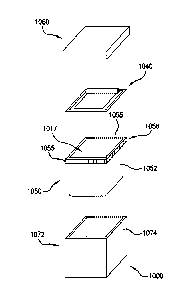
Figs. 12-14D illustrate another exemplary embodiment of the packaging system
1000
in which the plastic liner 1050 has a peel and reseal lidding assembly 1040.
It is appreciated
that the packaging system 1000 shown and described in Figs. 12-14 can include
one or more
of the features in any combination described in the other embodiments
described herein, or
the packaging system can include none of the previously described features.
For example,
the packaging system 1000 can include any combination of a carton 1002,
plastic liner 1050
having a rim 1005 peel and reseal lidding assembly 1040, and carton lid 1060.
As illustrated in Fig. 12, carton 1072 having side walls 1074 may receive the
liner
1050. The flange and bottom wall of the liner 1050 may support the liner 1050
in the carton
1072. A peel and reseal lidding assembly may be attached to the liner 1050 on
the flange
1055. A carton lid 1060 may include the liner 1050 and the peel and reseal
lidding assembly
within.
As illustrated in Fig. 13A, the peel and reseal lidding assembly 1040 may
include a
plurality of layers. For example, the peel and reseal lidding assembly 1040
may include a
lidding material 1006 and a peel-reseal lidding material 1008. The lidding
material 1006 may
be similar to or include features of the lidding material 140 or 340 described
above. The
lidding material 1006 may be sealed to the plastic liner 1050 and cover the
entire open area
1017 of the liner 1050. The lidding material 1006 may be a clear layer or an
opaque layer or
a translucent layer. The lidding material 1006 may be any suitable material
used in the
CA 02944615 2016-09-30
WO 2015/131137
PCT/US2015/018160
applicable industry. For example, coextruded nylon may be used. The lidding
material 1006
may have a thickness from 1-20 Mils. In one example, the lidding material may
have a
thickness of 4 Mils which, when paired with peel-reseal lidding material 1008,
the peel and
reseal lidding assembly 1040 may have a suitable rigidity and flexibility. For
example, the
lidding material 1008 may be sufficiently flexible to be folded over on itself
or rolled-up into
a roll while open. The lidding material 1008 may be sufficiently rigid to not
fall into the
opening under its own weight. The lidding material 1006 may be hermetically
heat-sealed or
laminated to the plastic liner 1050 such as described above.
The peel-reseal lidding material 1008 may comprise a first layer 1014 and a
second
layer 1024. One layer may be a layer operable to reseal an open container. One
layer may be
a stiffening layer. The stiffing layer may be operable to limit the peel-
reseal lidding material
1008 from folding over on itself under its own weight or small forces. The
second layer may
remain attached to at least a portion of the first layer. For example there
may be multiple
portions of the first layer as discussed below. The second layer may
detachably connect to
one portion of the first layer but remain attached to another potion as the
first layer is open
and closed along its opening.
The first layer may be any material that provides support to lidding material
1006 or
that provides a suitable oxygen barrier. For example, the first layer 1014 may
be a metallized
oriented polypropylene (NIOPP) layer. Metallized films are polymer films
coated with a thin
layer of metal, usually aluminum. They offer the glossy metallic appearance of
an aluminum
foil at a reduced weight and cost. Metallized films are widely used for
decorative purposes
and food packaging. Metallization is performed using a physical vapor
deposition process.
Aluminum may be a typical metal used for deposition, but other metals such as
nickel or
chromium are also used. The metal is heated and evaporated under vacuum. This
condenses
on the cold polymer film, which is unwound near the metal vapor source. This
coating is
much thinner than a metal foil (although a metal foil may also be used in
various
embodiments) could be made, in accordance with various embodiments in the
range of 40ga
to 100ga. For example, the first layer may be about 70ga MOPP. In various
embodiments,
either polypropylene, nylon, polyethylene, cast polypropylene and polyethylene
terephthalate
(PET) may be used with metallization.
In accordance with various embodiments, the second layer may be formed from
similar material as the first layer. However, the second layer may be formed
without
metallization. The second layer 1024 may hold the first layer 1014 closed with
an adhesive
applied to one side. Like the first layer, the second layer may be formed from
polypropylene,
21
CA 02944615 2016-09-30
WO 2015/131137
PCT/US2015/018160
nylon, polyethylene, cast polypropylene and polyethylene terephthalate (PET).
The second
layer may be formed from a variety of thicknesses such as 30ga to 90ga. For
example, the
second layer 1024 may be formed of about 50ga PET.
In accordance with various embodiments, the peel and reseal lidding assembly
1040
may be comprised of a stack of the second layer 1024 being 48ga PET with ink
applied to
nonstick areas (such as pull tab, see below) and with an adhesive applied to
one side, the first
layer 1014 being a 70ga Metallized OPP with an adhesive on both sides, and a
lidding
material 1006 being a 4Mil COEX nylon film adhered to one side of the first
layer. This
embodiment and similar embodiments may be used to package hot and cold
materials. The
assembly may have excellent hot tack and seal strength. The Metallized
Structure gives the
assembly improved oxygen and moisture barrier and good rigidity while
maintaining some
flexibility in order to keep the center portion 1018 (discussed in more detail
below) moveable
for opening.
To access the contents within the plastic liner 1050, the lidding material
1006 can be
broken, torn, cut, pierced through, or the like. For example, an X shaped cut
may open the
lidding material 1006 to provide access into the container. An example cut
1023 through the
lidding material is illustrated in Fig. 13D. Preferably, the lidding material
1006 can be
broken, torn, or pierced through using a sharp object such as a knife,
scissors, or the like. In
some configurations, an indicator or marking can be provided instructing a
user the preferred
area to cut.
As with other embodiments, the packaging system 1000 has sufficient strength
and
rigidity such that it passes the appropriate shipping tests under the
International Safe Transit
Association ("ISTA"). In particular, the sealed packaging system 1000
preferably has
sufficient strength and rigidity to pass the ISTA-3E shipping test or an
equivalent test that
challenges the capability of the packaging system and contents therein to
withstand transport
hazards. The lidding material 1006 also preferably acts as a tamper-evident
system and can
indicate to the user that the packaging system 1000 has been tampered with if
the lidding
material 1006 is broken.
Preferably, the peel-reseal lidding material 1008 is heat-sealed along its
edges 1002 to
the lidding material 1006 and/or plastic liner 1050. The peel-reseal lidding
material 1008
includes at least a first layer 1014 and a second layer 1024, such as a
sealing layer, that are
generally coextensive and adhered to each other. In the preferred embodiment,
the second
layer 1024 is permanently affixed to the first layer 1014 and the first layer
1014 is positioned
so that it faces the interior of the plastic liner 1050. The first layer 1014
and second layer
22
1024 can be of substantially the same size or in some configurations, the
second layer 1024
can be smaller than the first layer 1014. The lidding material 1008 may be
operable to lay
flat, peel back flat (e.g. Fig. 13C), and roll up (e.g. Figs. 12 and 13D). The
metallized layer
may provide suitable rigidity to control the characteristics of the lidding
material 1008.
In accordance with various embodiments, the liner 1050 may have any number of
sides or any shape. For example, the liner 1050 may be substantially
rectangular and the
lidding material 1008 may have four edges 1002 corresponding to the geometry
of the
opening of the liner 1050. It will be appreciated that other liner geometries
can be used, for
example and without limitation, the opening of the liner 1050 could be
circular, or polygonal
with more or less than four sides.
The first layer 1014 includes a center portion 1018 and a remaining area 1019
adjacent the center portion 1018. The center portion 1018 is positioned at a
predetermined
distance from the edge 1002 of the peel-reseal lidding material 1008. The
center portion
1018 is detached from the remaining portion 1019 along at least one edge 1022
such that the
center portion 1018 is movable to expose the lidding material 1006 (which may
be considered
a second lidding material) thereunder. The lidding material 1006 may be
defined by at least
one edge 1027. The lidding material 1006 may be sealed to the remaining
portion 1019 and
the center portion 1018 across the detached edge 1022. The peel-reseal lidding
material 1008
is resealable to seal the contents in the plastic liner when the lidding
material is broken. The
center portion 1018's detached edge 1022 may terminate in an inwardly turning
curve 1029.
In another example, as illustrated in Fig. 13G, 1022 may terminate in an
outwardly turning
curve 1031. The curve (inwardly or outwardly curving) turns at least 900. The
curve 1029,
1031 may turn about 180 . The termination points 1033 wraps back around toward
where the
center portion 1018 opens such that as the center portion opens and folds
across a hinge
section 1015, stress is reduced on the edge termination because the opening
action is not
pulled towards the termination but away from it, reducing the likelihood of
tearing. Once the
center portion 1018 is moved to an open position, the second lidding material
1006 is
exposed thereunder.
In various examples, the center portion 1018 may be defined by the at least
one edge
1022. The one edge may make a single slit for axis or it may make any of a
variety of shapes
to create an opening in the first layer 1014. In various examples, the center
portion 1018 may
be defined by four edges as illustrated in Figs. 13A-G. Although as
illustrated in Fig. 13F, the
at least one edge can have a variety of forms some of which are illustrated as
examples, but a
person of skill in the art would recognize that based on this disclosure any
shape may be
23
Date Recue/Date Received 2021-07-22
utilized. The detached edges 1022 may be
perforated, cut. or slit that separates the three edges of the center portion
1018 from the
remaining area 1019 of the first layer 1014. The fourth or remaining edge of
the center
portion 1018 is preferably affixed to the remaining area 1019 to act as a
hinge 1015 so that
the center portion 1018 can be pulled back to expose the lidding material 1006
thereunder.
The center portion 1018 of the peel-reseal lidding material 1008 can then be
resealed to seal
the open area 1017 of the plastic liner 1050 when the lidding material 1006
has been broken.
As the first layer is opened via the hinge, the second layer 1024 remains
attached to the center
portion 1018 while releasing from the remaining edge or area 1019.
The reseal is possible because an adhesive portion 1026 overlaps the detached
edges
1022 from the center portion 1018 to the remaining area 1019, such that when
the adhesive
portion 1026 is attached to the remaining area 1019 it is also attached to the
center portion
1018, thereby sealing the peal-reseal lidding material 1008. Adhesive portion
1026 may be a
distance of D wide as illustrated in Figs. 13B-C. D may be typically be
greater than 1/8 of an
inch. In various examples, D may be from 1/4 to 1/2 inch wide. The adhesive
portion 1026
includes a resealable adhesive 1010 on the bottom surface of the adhesive
portion 1026
facing the interior of the plastic lid 1002. As the user pulls back the center
portion 1018, the
adhesive portion 1026 is also pulled back with the center portion 1018. The
adhesive portion
1026 preferably includes a resealable adhesive material that can seal and
reseal multiple
times to facilitate resealing the center portion 1018 against the peel-reseal
lidding material
1008, for example, against the portion of the first layer 1014 adjacent the
center portion 1018
and edge 1002. The 1024 also extends across the curve 1029 and termination
points 1033.
As indicated above, the peel-reseal lidding material 1008 includes a tab 1012.
The tab
1012 may have similar adhesion to the rest of second layer 1024 or the tab
1012 may have
lower adhesion as compared to the rest of the layer 1024. In various
embodiments, tab 1012
may not be adhered to the lidding material 1006. This may allow the user to
easily grasp the
tab 1012 and pull back the center area 1018 of the peel-reseal lidding
material 1008 from the
lidding material 1006. In some configurations, the tab can be a portion of
either the first
layer 1014 or second layer 1024. In yet other configurations, no tab can be
provided. In one
example, the center portion's 1018 detached edge 1022 includes a first edge
1035 and a
second edge 1037 (see Fig. 13C). The peel-reseal lidding material 1008
includes a corner tab
1012 that is defined by an area where the first edge 1035 and the second edge
1037 meet at a
corner. The tab is operable to extend away from the surface of peel-reseal
lidding material
1008 such that it can be gripped and pulled. Tab 2012 may be movable such that
it can be
24
Date Recue/Date Received 2021-07-22
CA 02944615 2016-09-30
WO 2015/131137
PCT/US2015/018160
operatively pulled away from the first lidding material 1014. This separation
from lidding
material 1014 allows for separation between the portion of second layer 1024
and first layer
1014 which is attached along the remaining portion 1019. This attachment may
be adjacent
the first edge 1035 and the second edge 1037. The second layer 1024 is
separable from the
remaining portion 1019 starting at a point on either side and proximate to the
tab 2012. The
separation continues to move along both the first edge 1035 and the second
edge 1037 as the
tab is further moved from the first lidding material 1014. The separation
progresses moving
distally away from the tab 1012 as the tab 1012 is separated from the first
lidding material
1014. In yet other configurations, the tab can be located at an intermediate
length along any
edge, or no tab can be provided.
Fig. 14A-D illustrates various embodiments of liner 1050. With regard to the
various
embodiments as illustrated in Figs. 14A-E, all other embodiments, features,
and examples
described with regard to other embodiments may also be combined herein. The
liner 1050
may comprise at least one side wall 1052. In the example shown in Figs. 14A-E,
the liner
1050 includes four side walls 1052 and a bottom wall 1053. The four side walls
1052 define
an open area 1017. At the termination of the side walls 1052 distal to the
bottom wall 1053 is
a rim 1056. The rim 1056 may include a flange 1055 which extends outwardly
(i.e. away
from each of the side walls 1052.) The flange 1055 may include a skirt 1057.
The skirt 1057
may extend downwardly (i.e. toward a plane defined by the bottom wall but not
toward the
side walls).
In accordance with various embodiments, the liner 1050 includes a plurality of
positioning features. The liner 1050 is operable to be located inside of a
carton 1072. The
carton includes walls 1074 that define its perimeter. The liner 1050 and the
cavity defined by
walls 1074 may nest within each other, such that liner 1050 can be located
inside of the
interior of carton 1072. The liner 1050 may none-the-less shift within the
carton. The
packaging assembly 1000 is operable to be used safely and securely with a
broad range of
contents. As such, in various embodiments a snug fit between carton 1072 and
liner 1050
may improve the utility of the packaging assembly 1000. To that end in various
embodiments, the package assembly 1000 may include non-movement elements. Non-
movement elements may include protrusions that contact the carton 1072. For
example,
these may include skirt ribs, wall protrusions, specialized corners, or any
feature which limits
movement between the carton and the liner.
In various examples, a liner 1050 may rest on the top edge of wall 1074 via
the
flange portion 1055 which extends from the rim of liner 1050. The skirt 1057
provides a
CA 02944615 2016-09-30
WO 2015/131137 PCT/US2015/018160
pocket between the side wall 1052 and the interior surface 1059 of skirt 1057
to receive wall
1074 to aid in a more snug fit for the packaging assembly 1000. The skirt may
also include a
plurality of ribs 1071. The plurality of ribs 1071 may extend from or into the
surface 1059
of skirt 1057. The plurality of ribs 1071 extend from the flange portion 1055
down to the end
of the skirt. By forming these protrusions into or away from the skirt 1057,
the surface 1059
of the skirt is strengthened. The ribs may also act spacers to form a better
fit around the wall
1074. For example, ribs 1071 may extend toward side wall 1052 at a plurality
of finite
points. These finite points could interfere with the wall or merely close the
gap toward the
wall 1074 when the liner 1050 is installed in a carton 1072 and the wall 1074
extends into the
cavity between the skirt 1057 and the side wall 1052. Because the points are
spread and
friction and pressure are minimized, even if they interfere, they may not
prevent the liner
1050 from mating with the carton 1072. The skirt 1057 may also include a flare
1073 that
extends away from the side wall. The flare 1073 may also extend around the
perimeter. The
flare may be operable to help the skirt 1057 receive the wall 1074 when
inserting the liner
1050 into the carton 1073. As the flare 1073 extends away from the side wall
1052, the flare
1073 forms a wider entrance for receiving the wall 1074 into the gap between
skirt 1057 and
the side wall 1052.
The outer corner for the skirt may be any type of corner. For example, it
could be
round like the wall 1052 intersection. In another example, the skirt corner
could be different
than the wall 1052 corner. For example, the skirt corner may be a shape that
helps secure the
carton 1073. In one example, side walls 1052 may include a rounded corner
proximate the
side wall and the skirt may include a outer corner proximate the skirt. The
outer corner may
interface with other elements (see below) or its shape, alone, may improve
pressure on the
carton with the resultant improved fit.
The skirt includes a rib 1079 which extends generally parallel with the flange
portion
on at least one of the outer corners on the side of the skirt. The rib 1079
may be located
proximate the flange portion. The rib may form a ledge the aids in grabbing to
lift the liner
1050 or the rib may be a stiffening feature.
In accordance with various embodiments, the side walls 1052 may include
features to
improve fitment with the carton. For example, on each of the corners of the
side walls 1052 a
protrusion may be located adjacent the end of the skirt. The protrusion 1075
may be located
opposite the skirt and separate from the protrusion 1075 by the flange
portion. In this way
there is a gap between the end of the skirt and the protrusion. As stated
above, the skirt may
have a outer corner connection and the comer connection may be located
adjacent another
26
feature such as the protrusion 1075, which may also be located on the corners.
As such, the
carton may even receive a tighter fit when positioned between the outer corner
and the
protrusion 1075. The protrusion may be located anywhere on the liner 1050 such
that it is
operable to exert outward pressure when the liner is slid into a carton 1072.
However. by
placing the protrusion 1075 opposite the skirt 1057, a sandwich is formed.
thereby potentially
increasing the pressure from both sides on the wall 1074 and improving the
fitment. The
protrusion 1075 may be a protrusion that curves out and away from the side
wall 1052. The
protrusion 1075 may have a smaller curvature than the surface of sidewall 1052
such as the
surface at the rounded corner. The smaller curvature may result in improved
contact between
.. an outer surface of the protrusion and the carton as compared to an outer
surface of the
rounded corner. This is because the smaller curvature may make closer and more
complete
contact with the carton in a place such as a corner. In accordance with
various embodiments,
the protrusion 1075 may include a rib 1077. The rib 1077 may bisect the
protrusion
extending from a side of the protrusion 1075 proximate the bottom wall 1053 to
a side of the
.. protrusion proximate the flange 1055. The rib 1077 may add strength to the
protrusion such
that it is able to exert more outward pressure such as on the carton 1072.
In accordance with an exemplary method 1100 of forming the peel-reseal lidding
assembly 1040, the first layer may be obtained (step 1110). The first layer as
discussed above
may be a metallized OPP layer. This may come on large bulk rolls of material.
The center
portion may be cut into the first layer (step 1120). As discussed briefly
above, the first layer
may be cut, torn, perforated or the like to form the detached edge that
defines the center
portion. Once the first layer is prepped and the center portion is formed, the
first layer may
be attached to an additional layer. In one embodiment, it may be attached to
the second layer
which may be the layer that peels and reseals with the first layer.
Alternatively, the third
layer of material may be attached to the first layer next (1030). Either
order is
contemplated herein. The third layer of material may be the lidding material
106 which may
function as the tamper evident seal. The third layer may be heat-sealed to the
first layer. The
two layers may be cut such that they are coextensive with one another. A
finalized product
may be formed of a plurality of layers. Each may provide a separate function,
e.g. tamper
evident, oxygen barrier, peel-reseal characteristics.
In accordance with an exemplary process, as illustrated in Fig. 16, a system
may
prepare the packaging assembly 1000 on a production line. The system may
receive cartons
from a box erector, obtain liners, fill the liner, seal the peel-reseal
assembly onto the liner,
27
Date Recue/Date Received 2021-07-22
place the liner into the carton, places a carton lid onto the carton, and then
palletizes the final
packaging assembly.
Although various representative embodiments of this invention have been
described
above with a certain degree of particularity, those skilled in the art could
make numerous
alterations to the disclosed embodiments without departing from the spirit or
scope of the
inventive subject matter set forth in the specification. All directional
references
(e.g., upper, lower, upward, downward, left, right, leftward, rightward, top,
bottom, above,
below, vertical, horizontal, clockwise, and counterclockwise) are only used
for identification
purposes to aid the reader's understanding of the embodiments of the present
invention, and
do not create limitations, particularly as to the position, orientation, or
use of the invention
unless specifically set forth in the claims. Joinder references (e.g.,
attached, coupled,
connected, and the like) are to be construed broadly and may include
intermediate members
between a connection of elements and relative movement between elements. As
such, joinder
references do not necessarily infer that two elements are directly connected
and in fixed
.. relation to each other.
In some instances, components are described with reference to "ends" having a
particular characteristic and/or being connected with another part. However,
those skilled in
the art will recognize that the present invention is not limited to components
which terminate
immediately beyond their points of connection with other parts. Thus, the term
"end" should
be interpreted broadly, in a manner that includes areas adjacent, rearward,
forward of, or
otherwise near the terminus of a particular element, link, component, part,
member or the
like. In methodologies directly or indirectly set forth herein, various steps
and operations are
described in one possible order of operation, but those skilled in the art
will recognize that
steps and operations may be rearranged, replaced, or eliminated without
necessarily departing
from the spirit and scope of the present invention. It is intended that all
matter contained in
the above description or shown in the accompanying drawings shall be
interpreted as
illustrative only and not limiting. Changes in detail or structure may be made
without
departing from the spirit of the invention as defined in the appended claims.
28
Date Recue/Date Received 2021-07-22