Note : Les descriptions sont présentées dans la langue officielle dans laquelle elles ont été soumises.
CA 02945225 2016-10-13
Field of the Invention
[0001] The present concept relates to a device for measuring and analysing
colours
and more particularly it relates to a small handheld inexpensive colour
measuring device
which can interface via Bluetooth with smartphones and convert the colour
readings into
any number of current colour models, or spaces.
Background of the Invention
[0002] There is a need to quickly and accurately be able to measure
colours on a
variety of different surfaces and convert the colour measurement into a number
of standard
colour spaces.
[0003] There are a number of prior art devices which have attempted to measure
colour
each with shortcomings normally related to accuracy reproducibility,
portability, cost of
manufacture and inability to convert readings into a number of standard colour
spaces used
by different industries.
[0004] Studies have shown that there exist a cultural preference in the colour
of the food
people consume, therefor in the egg industry the colour of the yolk is closely
controlled and
a vital step in the control process is accurately measuring the yolk colour.
There is a need
2
CA 02945225 2016-10-13
for a quick, accurate and cost effective way of measuring the colour of the
egg yolk.
[0005] A number of prior art devices exist in the industry that can be
utilized to measure
the colour of the yolk. Two such methods are the DSM Egg yolk colour fan and
the egg
quality measurement device. Though both methods can provide the measurements
but they
are not without their limitations and shortcomings. The egg yolk colour fan is
fast and
inexpensive, given it is a qualitative method of comparing coloured swatches
to the yolk via
the naked eye, it's accuracy and precision is a function of the end user. The
second method
mentioned is the egg quality measuring device, which utilizes a colour sensor
and a light
source. The light illuminates the yolk at prescribed angle and the reflected
light is diffused
into the sensor. This method is more accurate and precise since it is
quantitative, but the
size, complexity and cost of the apparatus make it less appealing to the end
users.
Summary
[0006] The present concept is an egg yolk cover for housing the liquid portion
of an egg
between the cover and a flat surface for the purpose of measuring egg yolk
color. The egg
yolk cover comprises:
a) an opaque cover adapted to cover the liquid portion of an egg, the
cover includes a base edge which contacts with the flat surface and
adapted to create a substantially light tight seal with the flat surface;
3
CA 02945225 2016-10-13
b) wherein the cover includes a transparent inspection area adapted for
viewing the egg yolk.
[0007]
Preferably wherein the cover is dome shaped and includes a flattened crown
portion which is substantially parallel to the flat surface.
[0008]
Preferably wherein the inspection area is an aperture in the flattened crown
portion.
[0009]
Preferably wherein the aperture includes a transparent window within the
aperture which impinges onto the egg yolk.
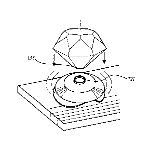
[00010]
Preferably wherein the cover defines a yolk depth wherein the flattened
crown portion is dimensioned to be at a preselected height above the flat
surface and
selected to fall in the range from 6 to 12mm inclusively.
[00011]
Preferably wherein the cover defines a preselected volume between the cover
and flat surface which is sufficient to house the egg yolk.
[00012]
Preferably wherein the preselected volume is selected to fall in the range
from
20 ml to 40 ml inclusively.
[00013] The
present concept is also a method of determining the color of an egg yolk.
The method comprises the following steps:
a) cracking an egg onto a flat surface such that a liquid portion rests on the
flat
surface;
4
CA 02945225 2016-10-13
b) placing a cover over the egg yolk the cover includes;
i. an opaque cover adapted to cover the liquid portion of an egg, the
cover includes with a base edge which contacts with the flat surface
and adapted to create a substantially light tight seal with the flat
surface;
ii. wherein the cover includes a transparent inspection area adapted for
viewing the egg yolk;
c) deploying a color sensor onto the inspection area to measure the yolk
color.
[00014] Preferably wherein the cover is dome shaped and includes a
flattened crown
portion which is substantially parallel to the flat surface.
[00015] Preferably wherein the inspection area is an aperture in the
flattened crown
portion.
[00016] Preferably wherein the aperture includes a transparent window
within the
aperture which impinges onto the egg yolk.
[00017] Preferably wherein the cover defines a yolk depth wherein the
flattened
crown portion is dimensioned to be at a preselected height above the flat
surface and
selected to fall in the range from 6 to 12mm inclusively.
[00018] Preferably wherein the cover defines a preselected volume between
the cover
and flat surface which is sufficient to house the egg yolk.
[00019] Preferably wherein the preselected volume is selected to fall in
the range from
20 ml to 40 ml inclusively.
CA 02945225 2016-10-13
[00020] Preferably wherein the light sensor is a portable colour sensor for
measuring
colour of a substrate comprising:
a) a single flat printed circuit board with a top & bottom side which includes
at
least one LED light and one colour sensor;
b) at least one light pipe receiving light from the LED and transmitting it
onto a
substrate at an angle theta;
c) a tube frame including an optical tube for receiving light reflections from
the
substrate; and
d) wherein the light pipes and the tube frame, are compression fit between the
printed circuit board and a lower housing.
[00021] Preferably wherein the LED light is directed perpendicularly away
from the
printed circuit board and wherein the light pipe is an arcuate member bending
the light to
achieve the angle theta.
[00022] Preferably wherein the light pipe abutting at one end to the LED
and
connecting at the other end at a light emitting port in the lower housing.
[00023] Preferably wherein the light emitting port is located within a
light cavity
which is an inverted dome with the bottom terminating at a contact surface.
[00024] Preferably wherein the flattened crown portion contacting with the
contact
surface of the lower housing of the lower housing of the colour sensor.
Brief Description of the Drawings
6
CA 02945225 2016-10-13
[00025] The
present concept will be described by way of example only with reference
to the following drawings in which:
[00026]
Figure 1 is a partial side cross sectional view of the printed circuit board
used
in the present concept together with the gasket mounted on the bottom side and
electrical
components on the top side.
[00027]
Figure 2 is a schematic partial cross sectional view of the printed circuit
board shown together with an optical tube and light pipes mounted onto a
sealing surface
of a gasket.
[00028]
Figure 3 is a schematic cross sectional view of the print circuit board
together with light pipes and a tube frame mounted in a lower housing and an
upper
housing.
[00029]
Figure 4 is a top schematic plan view of the print circuit board mounted into
the lower housing.
[00030]
Figure 5 is a top plan view of the lower housing prior to the installation of
the
7
CA 02945225 2016-10-13
light pipes and tube frame and printed circuit board.
[00031] Figure 6 is schematic perspective view of the light pipe.
[00032] Figure 7 is an inverted schematic exploded view of the printed
circuit board
together with the tube frame, light pipes, and the lower and upper housings.
[00033] Figure 8 is a schematic cross sectional view of the colour sensor
in figure 3
mounted on a dome shaped cover, deployed onto an entire egg yolk in its cavity
on top of
an opaque flat surface.
[00034] Figure 9 is an perspective view of the top of the dome shaped
cover.
[00035] Figure 10 is a side cross sectional view of the dome shaped cover.
[00036] Figure 11 is an perspective view of the bottom of the dome shaped
cover.
[00037] Figure 12 depicts the first step in the method of preparing an
egg: cracking the
egg and placing its content on a flat opaque surface.
8
CA 02945225 2016-10-13
[00038] Figure 13 depicts the method of preparing an egg: allowing the yolk
to spread
evenly over the flat surface.
[00039] Figure 14 depicts the procedure for deploying the dome shaped cover
over the
yolk.
[00040] Figure 15 depicts moving the cover for ensuring an unobstructed
view and
full contact between the yolk and the transparent window within the aperture.
[00041] Figure 16 depicts the procedure for attaching the colour sensor in
figure 3 to
the dome shaped cover once a proper and unobstructed contact with the yolk has
been
established.
[00042] Figure 17 illustrates a fully assembled apparatus with the colour
sensor
attached to the dome shaped cover deploying onto a yolk over a horizontal
solid surface.
Detailed Description of the Preferred Embodiments
9
CA 02945225 2016-10-13
[00043] Components of the present concept the portable colour sensor 100
are
depicted in the attached figures and shown in various stages of assembly and
completion for
the benefit of the reader.
[00044] Figure 1 for example shows the single printed circuit board PCB 102
used in
the present concept together with a gasket 104 mounted on a bottom side 106
having
openings 109 for LEDS 108 and opening 111 for colour sensor 110. Colour sensor
110 is
a true colour sensor rather than an RGB sensor.
[00045] PCB 102 includes a top side 112 at least one integrated circuit 114
a battery
116 and a hard wired interface namely a micro USB port 118 for calibration and
data
exchange purposes.
[00046] Figure 2 shows the orientation of various additional components
relative to
the print circuit board 102 namely left and right light pipes 120 each also
having a first
flange 122 and a second flange 124, a receiving end 126 and a transmitting end
128.
Receiving end 126 abuts against gasket 104 in order that light from LEDS 108
can be
transmitted down through light pipe 120 and out through transmitting end 128.
[00047] Further there is a tube frame 130 which includes an optical tube
132 having
a tube end 134 also abutting and mounted onto gasket 104 for receiving light
through
optical tube 132 and transmitting the received light onto colour sensor 110.
CA 02945225 2016-10-13
[00048] The components are not assembled in the condition shown in Figure 2
but
rather only the orientation of these components relative to the print circuit
board in shown
in Figure 2.
[00049] Figure 3 shows the assembly of the printed circuit board 102
together with the
light pipes 120 and the tube frame 130 all mounted into lower housing 140 and
capped off
with an upper housing 142 at a joint 144. All of the internal components are
compression
fit show by arrows 146 wherein the PCB 102 is urged downwardly into lower
housing 140
thereby pushing downwardly upon the light pipes 120 and tube frame 130, in
effect creating
a sandwich effect wherein the light pipes 120, tube frame 130 and dust cover
152 are held
in place.
[00050] Lower housing 140 also includes a lens dust cover 152, a receiving
port 150
and defines a contact surface 148. Lower housing 140 also includes light
emitting ports 154
and a light cavity 156. Light enters through light emitting ports 154 at an
angle theta 158.
[00051] Figure 4 is a schematic plan view of the bottom side 106 of printed
circuit
board 102 with one light pipe 120 shown in position wherein on the other side
the LED 108
is clearly visible through opening 109 in gasket 104. Also shown in position
is tube frame
11
CA 02945225 2016-10-13
130 and dust cover lens 152 at the bottom of receiving port 150. Additionally
the first and
second flanges 122 and 124 of light pipe 120 are also visible together with
the joint 144 of
the upper housing 142.
[00052] Figure 5 is a plan view looking into the cavity of lower housing
140 with all
of the components removed showing a set of four light pipe ribs 170 each
having a first slot
172 and a second slot 174 that register and slideably engage with first flange
122 and
second flange 124 respectively of light pipe 120.
[00053] There are four additional support ribs 176 upon which the printed
circuit
board 102 rests and three abutments 178 each with a screw hole 180 for
fastening print
circuit board onto lower housing 140.
[00054] The reader will see that the first flange 122 slideably engages
with first slot
172 and second flange 124 of light pipe 120 slideably engages with second slot
174. In this
manner light pipes 120 are slideably urged into position into the lower
housing 140.
Additionally dust cover lens 152 is placed into the bottom of tube receiver
182 and optical
tube 132 is slideably received within tube receiver 182 thereby placing tube
frame 130 in
place into lower housing 140.
[00055] Thereafter PCB 108 is adhered to with gasket 104 at contact surface
111 is
12
CA 02945225 2016-10-13
further placed with sealing surface 107 on top of the light pipes and the tube
frame 130
thereby compressing gasket 104 which is made of a resiliently biased material
in order to
create a seal around the base 190 of tube frame 130 and also a seal around the
receiving end
126 of light pipe 120 thereby ensuring that light which is conducted down
light pipe 120 is
not inadvertently transmitted into optical tube 132 directly from LED 108 or
indirectly from
light pipes 120. Contact surface 111 and sealing surface 107 preferably have
pressure
sensitive adhesive thereon.
[00056] Figure 7 schematically shows the orientation of lower housing 140
relative to
the upper housing 142 and the print circuit board 102 and the light pipes 120
and the tube
frame 130.
[00057] Figure 3 shows the angular relationship theta 158 of the light
relative to the
contact surface 148. This geometrical layout is often referred to as a 45/0
geometry in
which illumination of the sample is accomplished at an angle of 45 and the
colour sensor
110 receives a portion of the light reflected from the sample at an angle of
approximately
00 plus or minus 8 . This geometry is used in order to minimize specular
reflections and
allow only few reflections to be transmitted through the optical tube 132.
[00058] In order to reduce manufacturing costs, time and componentry light
pipes 120
13
CA 02945225 2016-10-13
have been configured such that a single liac print circuit board PCB 102 can
be utilized to
mount all of the electrical and electronic componentry.
[00059] The LEDS used have a broad parallel spectrum of visible light such
that all
wavelengths of visible light are emitted by the LEDS 108. In order to ensure
consistency
and reproducibility components having extremely low drift and low temperature
coefficient
variances are utilized throughout the device.
[00060] Readings obtained from the colour sensor are fed through on board
integrated
circuitry processing units which provide a predictable, stable and
reproducible output.
[00061] The unit includes an integral Bluetooth transmission device for
wirelessly
transmitting data to a smartphone which together with a smartphone application
for
presenting the data in usable format.
[00062] It is also possible to communicate through a hardwired mini USB
port 118 to
a laptop or other computer. The device is calibrated through the hardwired
mini USB port
118 prior to the shipping.
[00063] The outputs are converted into usable colour spaces including the
well known
RGB colour space, HSL colour space, HSV colour space, LAB colour space, XYZ
colour
14
CA 02945225 2016-10-13
space and is also converted into HTML, CMYK or Pantone units. The processor
software
application is able to convert to any print system using a delta e calculation
to determine
what available paint is closest (mathematically) to the scanned sample.
[00064] The contact surface 148 is placed against a substrate or surface
159 to be
analysed for colour such as a painted wall, skin, and a host of other surfaces
and materials.
[00065] Light emitted from is conducted down light pipes 120 and exits into
light
cavity 15 at an angle theta 158 onto a substrate 159 to be measured. Some of
the light is
reflected back up optical tube 132 where it is received by color sensor 110
and a
measurement is taken and recorded.
[00066] Components of the present concept the yolk colour sensor are
depicted in the
attached figures and shown in various. stages of assembly and illustrates the
method and
apparatus for the benefit of the reader.
[00067] Figure 8 shows a cross sectional view of the dome shaped cover 200
deployed
with a colour sensor 100 that will house an egg yolk 202 over a substantially
horizontal flat
surface 210. The base edge 204 makes contact with the horizontal flat surface
210
providing a circumferential light tight seal, thus minimizing the intrusion of
the outside
light.
CA 02945225 2016-10-13
[00068] There exists a flattened crown portion 206 that is substantially
parallel in
relation to the horizontal flat surface 210. This feature ensures that the
yolk top surface 220
is parallel in relation to the transparent window 208, which is critical in
producing the
desired reflection and refraction angles. Transparent window 208 as depicted
is preferably
round however could also be a multitude of other shapes including but not
limited to: square,
triangular or a polygon. Transparent window 208 is preferably made of
transparent plastic
having known optic properties, but may also be made of other materials such
as, including
but not limited to, glass with known optic properties.
[00069] Situated at the centre of the flattened crown portion is the
transparent
inspection area 212 containing an aperture 214 with a transparent window 208
onto which
the yolk top surface 220 impinges, continuously making contact with
transparent window
208.
[00070] Now also referring to figure 10, the geometry of the dome shaped
cover is
selected such that its cover volume 218 will substantially fully house the egg
yolk 202 with
some small amount of egg white 232 at the periphery 230 of the cover 203. The
dimensions
of cover 203 are selected such that a predetermined consistent yolk depth 216
and cover
volume 218 are maintained. Yolk depth 216 measures from the horizontal surface
102
16
CA 02945225 2016-10-13
upward to the lower face 244 of transparent window 208.
[00071] Cover volume 218 of dome shaped cover 200 is approximately 30 ml
was
derived using the 95th percentile confidence interval of a normal distribution
of egg yolk
volumes. The yolk depth 216 is approximately 9 mm, which by trial and error
measurements were found to be the optimal yolk depth 216 to obtain consistent
results.
With the desired cover volume and yolk depth the diameter of the cover 203
results in an
outer diameter of approximately 74mm. In practice the cover volume 218, yolk
depth 216
and the circumference can vary substantially and still provide adequate
results, but via
extensive trials it was found the geometry and dimensions proposed provide
optimal,
consistent and accurate results.
Method of preparing the egg and deployment of apparatus
[00072] Referring now to Figures 12 to 17 the method of preparing the egg
and
deployment of apparatus for determination of colour will be described.
[00073] Figure 12 depicts cracking an egg 220 and carefully separating the
eggshell
218 from its inner contents, egg white 232 and egg yolk 202, and gently
placing the contents
on a horizontal flat surface 210 preserving the integrity of the egg yolk 202.
It is vital that
17
CA 02945225 2016-10-13
the egg yolk 202 is fully intact and does not rupture the vitelline membrane
250 in this
process (breaking the yolk).
[00074] Figure 13 depicts a fully intact egg yolk 202 surrounded by the egg
white 232
placed onto a horizontal flat surface 210 after a short rest period. The
resting period allows
gravity to settle the egg white 232 away from the top of the egg yolk 202,
where the lower
face 244 of transparent window 208 impinges onto the yolk top surface 220.
This process
allows for an unobstructed view to the yolk.
[00075] Figure 14 depicts the recommended way of deploying the dome shaped
cover
200 vertically downwards onto the egg yolk 202. This method is recommended as
it affords
a simultaneous overview of both the egg yolk and dome shaped cover 200 thus
enabling the
operator to gauge fit over the egg yolk 202. Placing the cover using other
methods such as
tilting the cover over the yolk may result in rupturing the vitelline membrane
250. The egg
yolk 202 may rupture if caught between the horizontal flat surface 210 and
base edge 204.
[00076] Observing via transparent window 208 a full and unobstructed
contact
between the yolk top surface 220 and the transparent window 208 can be
ensured. Opaque
ropes of egg white known as the chalaza anchor the yolk in the centre. The
chalaza may get
positioned between the transparent window 208 and the egg yolk 202, may lead
to
18
CA 02945225 2016-10-13
erroneous measurements.
[00077] Figure 15 depicts that moving the dome shape cover 200 side to side
as shown
by arrow 271 in the event that the chalaza does obstruct the window, one can
clear the
window using this method. This provides a visual quality control ensuring that
the egg yolk
202 positioned below the transparent window 208 is consistently free of
unwanted
obstructions such as the chalaza.
[00078] Figure 16 depicts the recommended method of deploying the colour
sensor
100 onto the cover 200. The mechanism by which the two components interlock
involve
the coupling of flange 222, best represented in figure 10, to the docking
surface 155, best
represented in figure 3. The method recommended to accomplish the coupling is
by
securely holding down the cover 203 with one hand and deploying the colour
sensor 100
vertically downwards onto the cover. By attaching the colour sensor vertically
downwards
on to the widow 208 of the dome shape cover 200 minimizes the lateral
movements that the
cover would experience thus minimizing the disturbance experienced by the egg
yolk 202.
Minimizing any disturbance will reduce the possibility of egg yolk 202 to
rupture and also
retain the substantially unobstructed view obtained via methods described
above.
[00079] At this point the colour measurement is taken and recorded as
described for
19
CA 02945225 2016-10-13
the portable colour sensor 100 above.
[00080] It
should be apparent to persons skilled in the arts that various
modifications and adaptation of this structure described above are possible
without
departure from the spirit of the invention the scope of which defined in the
appended claim.