Note : Les descriptions sont présentées dans la langue officielle dans laquelle elles ont été soumises.
CA 02945657 2016-10-13
WO 2015/173125 PCT/EP2015/060139
1
Modular beverage preparation device for portable and
stationary use
Field of the invention
The present invention relates to a modular beverage
preparation device for preparing a beverage from a beverage
ingredients containing capsule. In particular, the present
invention relates to a portable beverage preparation device
for stationary and mobile use.
Background of the invention
Devices for preparation of a beverage such as coffee or tea
from ingredients containing capsules are well-known in the
prior art. These devices are generally stationary devices
equipped with a liquid tank, a pump and heating means in
order to provide pressurized, heated liquid through a
capsule inserted into the device. The liquid is injected
into the capsule and will interact with the ingredients
provided in the capsule. The resulting beverage is then
drained from the capsule and may be collected in a
dedicated receiving vessel.
A drawback of the known systems is the fact that these
devices are designed for stationary use only. This means
that the device has to be placed at a fixed location within
the household, close to a main power supply. In addition,
the device has to be placed close to a water supply in
order to enable filling or re-filling of the liquid into
the liquid tank of the device. The beverage preparation can
CA 02945657 2016-10-13
WO 2015/173125 PCT/EP2015/060139
2
thus only be carried out at the predefined stationary
location of the device.
Therefore, portable devices have been proposed which enable
the preparation and provision of a hot beverage such as in
particular a coffee beverage at remote places.
EP 1 277 428 for example relates to a portable espresso
coffee machine designed for a low-voltage vehicle,
comprising a water reservoir connected to a pump to convey
water to a heating element, which itself is connected to an
extraction head for a portion of coffee. The device is
adapted for being used in conjunction with a low voltage
source of between 12 to 50 Volts such as present e.g. in a
car or a boat. Further, the device is adapted for reducing
or cutting-off the heating of the heating element in case
the pump is activated during beverage preparation.
US 2009/0029021 relates to a portable device for brewing a
coffee beverage, the device comprising a water tank, a
housing including a chamber presenting a hot water feed
nozzle and an opening through which a fill of brew
preparation can be inserted, a closure part for closing
said chamber, means connected to the tank to act during a
brewing cycle to deliver a certain volume of water that has
been raised to a brewing temperature from said tank to said
chamber, and a brew outflow orifice from which the
resulting beverage may be poured into a suitable receiving
vessel. The device comprises an optionally re-chargeable
battery for powering a pump and water heating means, which
battery may be arranged in a handle of the device.
WO 2011/135539 relates to a beverage preparation machine
comprising a fixed part and a movable part which can be
coupled and uncoupled to/from each other and are provided
with respective cooperating means for providing electric
CA 02945657 2016-10-13
WO 2015/173125 PCT/EP2015/060139
3
and fluid connection. The movable part of the machine
comprises water inlet means, a pump, a dedicated boiler
connected to the pump and a brewing chamber for the coffee
beverage. Water provided to the water inlet means at
ambient temperature is continuously heated in the boiler of
the machine in order to provide heated water to the brewing
chamber. When connected to the fixed part of the device,
the pump and the boiler of the movable part are connected
with a liquid reservoir of the fixed part.
A drawback of this machine is the relative large dimensions
of the movable part of the device that limit its
versatility as portable device. In addition, the boiler
arrangement for constantly heating the water leads to a
relatively high energy consumption as not only the amount
of liquid necessary for preparation of a serving of the
coffee beverage is heated, but also the following water
which replaces this amount in the boiler of the machine.
In view of the known prior art appliances, the present
invention seeks to address the problem of providing a
beverage preparation device and a system enabling an
enhanced versatility and providing for a reduced energy
consumption of the device. The present invention also seeks
to address further problems as will become apparent in the
following description.
Object and Summary of the invention
In a first aspect, the invention relates to a portable
beverage preparation device for preparing a beverage from
an ingredients containing capsule, the device comprising: a
beverage brewing unit for receiving the capsule and
preparing the beverage from the ingredients within the
CA 02945657 2016-10-13
WO 2015/173125 PCT/EP2015/060139
4
capsule by means of injection of liquid into the capsule, a
liquid reservoir designed for holding a predefined liquid
volume suitable for preparing the beverage, a pump unit
adapted for providing pressurized liquid to the beverage
brewing unit, and heating means arranged within the liquid
reservoir and adapted for heating the liquid volume,
wherein the device further comprises a multifunctional
connector adapted for selectively connecting the device
electrically and mechanically to a remote power source.
The invention enables the provision of a compact beverage
preparation machine having the heating means arranged
directly in the liquid reservoir of the device.
Accordingly, the required space for the individual
components within the device is reduced. At the same time,
the versatility of the device is increased. Thereby, the
single multifunctional connector of the device enables a
compact embodiment as well as providing for the selective
connection to a plurality of different power sources in
order to enable e.g. a portable or stationary use of the
device. Moreover, the energy consumption of the device is
reduced as only the amount of liquid respectively the
liquid volume provided in the liquid reservoir is heated.
It is noted that the term "portable" beverage preparation
device is to be understood as suitable for being used at
remote places by contrast to a stationary beverage
preparation device. Thereby, portable means in particular
that a human can easily and conveniently carry the device
e.g. by hand or in a small suitcase. The device is
preferably void of a large liquid reservoir that would
significantly add to the weight and size of the beverage
preparation device.
CA 02945657 2016-10-13
WO 2015/173125 PCT/EP2015/060139
The heating means are preferably adapted to be activated in
response to a command of the user of the device. Thereby,
the heating means are preferably activated by the user
shortly before the injection of the liquid into a capsule
5 placed into the brewing unit. This may be obtained manually
upon pressing a dedicated activation button of the heating
means or automatically upon activating the device. The
heating means are preferably designed to heat the volume of
liquid contained in the liquid reservoir to a predefined
temperature, which preferably lies between 85 and 95 C.
In a preferred embodiment, the heating means are preferably
designed for heating the liquid volume contained in the
reservoir to about 90 C in 2-4 minutes, preferably in about
3 minutes after activation. The heating means of the device
preferably have a power of 1800W.
In a preferred embodiment, the liquid reservoir of the
device is designed for holding a volume of liquid suitable
for preparing a single serving of the beverage. The liquid
reservoir preferably comprises a volume of between 30 to
60m1, preferably between 35 and 45 ml. In a particularly
preferred embodiment, the liquid reservoir comprises a
liquid volume to prepare a cup of espresso-type beverage.
Due to a relatively small volume of the liquid reservoir,
heating of the liquid contained therein is accelerated.
The multifunctional connector of the device is preferably
adapted for electrically and mechanically connecting the
device to two or more of the group consisting of a docking
station, a battery unit, and a low voltage power cable.
Thereby, these entities are preferably designed to function
as power source for the operation of the device.
CA 02945657 2016-10-13
WO 2015/173125 PCT/EP2015/060139
6
The multifunctional connector is preferably void of any
fluid connection or fluid communication means.
In a preferred embodiment, the portable device is adapted
at least for mobile use in conjunction with the battery
unit, for a virtual mobile use, preferably in conjunction
with a car power adapter, and for stationary use in
conjunction with the docking station.
The device is preferably adapted for being operated by a DC
input current supplied by the multifunctional connector.
Thereby, the device is preferably void of any further
electrical supply means. This means that the device
respectively the electric components of the device are
electrically driven only by the DC input current provided
via the multifunctional connector.
The device is preferably adapted for receiving a DC input
current of preferably 12 to 15 Volts. A dedicated docking
station and/or power adapter to which the device may be
connected via its multifunctional connector preferably
comprises and AC/DC power converter which provides adequate
input voltage to the device.
The beverage preparation device is preferably designed for
preparing hot beverage and in particular espresso-type
coffee at high pressure. Thereby, the device is designed
for providing high water pressure supply and high water
temperature setting. The device is preferably designed for
preparing a beverage at a high pressure of between 10 to 15
bar. The heating means of the device preferably comprises
two cartridge heaters designed for being supplied with 12
Volts nominal voltage.
CA 02945657 2016-10-13
WO 2015/173125 PCT/EP2015/060139
7
The pump of the device is preferably a membrane pump. The
pump is preferably vibration-decoupled from a housing of
the device. The membrane pump is preferably designed to
enable the provision of the preferred pressure between 10
to 15 bar while at the same time it can be driven by means
of a low DC voltage electrical motor. It is noted that the
use of a membrane pump prevents cavitation problems due to
its flexibility.
The device preferably comprises a user interface which
comprises at least one start/stop button. The button is
preferably a switch with background lighting designed for
enabling a relatively simple feedback concerning the
operation state of the device to the user. The use of a
simple switch or button with e.g. background lighting
enables the minimization of the power consumption by the
user interface. In particular, the switch may blink during
preheating of the liquid such as water in the reservoir and
turn to a ready-mode, e.g. with continuous lightening, when
the water is at the brewing temperature. This can be sensed
by a dedicated temperature sensor of the device. The switch
may be designed for indicating by colour change, the power
status of the device. In particular, a red coloured switch
may relate to an insufficient available power such as low
battery installed; a green coloured switch may relate to a
correctly energized device on any electric power supply.
In a preferred embodiment, the device further comprises
connection means for selectively connecting to a receptacle
and for dispensing the resulting beverage from the brewing
unit to the receptacle. Thus, the connection means
preferably comprise integrally formed beverage dispensing
means such as an integrally formed beverage dispensing
outlet for providing the resulting liquid from the brewing
unit to the receptacle. The beverage dispensing means
CA 02945657 2016-10-13
WO 2015/173125 PCT/EP2015/060139
8
preferably protrude from an upper portion of the beverage
brewing unit. In a particularly preferred embodiment, the
beverage dispensing means protrude from a support surface
for a receptacle arranged above the brewing unit. The
support surface is preferably a plane and/or round surface
arranged at a top portion of the beverage preparation
device.
Note that directions and orientations such as e.g. the
terms "upper", "lower", "above" and "below" are to be
understood as referring to a working state of the portable
beverage preparation device and not to an orientation of
the device during transport or storage.
In a working state of the portable beverage preparation
device, the brewing unit is arranged above the liquid
reservoir and the pump in the beverage preparation device.
The beverage dispensing means are preferably arranged above
the beverage brewing unit. A receptacle to be filled is
preferably arranged above the beverage brewing unit and the
beverage dispensing means. In a particularly preferred
embodiment, at least the pump, the beverage brewing unit
and the beverage dispensing means of the device are
preferably arranged essentially vertically, such as in
particular vertically stacked within the device.
The flow path of liquid through the beverage brewing unit
and the beverage dispensing means is preferably in a common
direction. In particular, the flow path of liquid from the
pump of the device to the beverage brewing unit and the
beverage dispensing means is in a common direction.
Thereby, in a working state of the beverage preparation
device, the flow path of liquid through the above-indicated
components of the device is preferably orientated
vertically against gravity. Accordingly, a receptacle
CA 02945657 2016-10-13
WO 2015/173125 PCT/EP2015/060139
9
connected to the beverage dispensing means will be filled
from below with the dispensed beverage.
According to such an arrangement, the distances between the
individual components of the device are minimized such as
to obtain a very compact arrangement of the beverage
preparation device. Thereby, also the tubing necessary to
fluidly connect the individual parts of the device may be
shortened and hence, the risk of contamination with
bacteria or the like is minimized.
The brewing unit of the device is preferably designed to
accommodate a rotational-symmetric capsule comprising a
truncated-cone shaped body portion and a membrane connected
to a circumferential rim portion of the body portion and
constituting an outlet face thereof. The capsule is
arranged within the brewing unit such that the
circumferential rim portion and the membrane connected
thereto are arranged at the upper side of the capsule.
A further aspect of the invention relates to a portable
beverage preparation device for preparing a beverage from
an ingredients containing capsule, the device comprising a
beverage brewing unit for receiving the capsule and
preparing the beverage from the ingredients within the
capsule by means of injection of pressurized liquid into
the capsule, a lid member selectively connectable to the
brewing unit in order to enclose a capsule provided
thereto, wherein the lid member preferably comprises
beverage dispensing means designed to selectively connect
to a receptacle, preferably to a bottom of a receptacle,
and wherein the beverage brewing unit is arranged moveable
within a housing of the device such as to selectively open
a fluid-connection from the brewing unit to a fluid
reservoir of the device.
CA 02945657 2016-10-13
WO 2015/173125 PCT/EP2015/060139
Accordingly, in case of the open fluid-connection from the
brewing unit to the fluid reservoir, refilling of the fluid
reservoir of the device via filling of liquid into the
5 empty brewing unit is enabled. A user may thus remove the
lid member from the brewing unit respectively the housing
of the device and simply fill a predefined amount of liquid
into the brewing unit in order to refill the liquid
reservoir. Hence, a dedicated separate aperture or valve
10 means at the device suitable for refilling purposes of the
liquid reservoir may be omitted.
In a preferred embodiment, the fluid-connection from the
brewing unit to the fluid reservoir is opened dependent on
the provision of the lid member to the device respectively
the brewing unit. Thereby, in case no lid member is
arranged at the device, the beverage brewing unit is
preferably urged in a direction away from the fluid
reservoir such as to open a dedicated valve means, e.g. an
annular passage enabling fluid flow from the beverage
brewing unit to the liquid reservoir. This may be obtained
by spring members that are arranged at the brewing unit.
Upon closing of the lid member onto the device respectively
the brewing unit, the brewing unit is urged in a direction
towards to fluid reservoir, whereby the valve means, e.g.
the annular fluid passage from the brewing unit to the
liquid reservoir is closed.
In a further aspect, the invention relates to a beverage
preparation kit respectively a beverage preparation system,
the kit respectively the system comprising a beverage
preparation device as described above, a docking station
and a battery unit, wherein the docking station and the
battery unit comprise the same connection means adapted for
CA 02945657 2016-10-13
WO 2015/173125 PCT/EP2015/060139
11
being selectively connected electrically and mechanically
to the multifunctional connector of the device.
The connection means are preferably void of any fluid
connection.
In a preferred embodiment, the kit further comprises a low
voltage power cable and/or a car power adapter having the
same connection means than the docking station and the
battery unit and which are adapted for being electrically
and mechanically connected to the multifunctional connector
of the device.
The docking station preferably comprises at least one
charging member respectively charging dock to which the
connection means of the battery unit of the system may be
connected for charging. The docking station is preferably
designed for providing an electrical and mechanical
connection for the portable beverage preparation device and
at least one battery unit at the same time. The docking
station is preferably designed for being connected to the
mains. Thereby, the docking station is preferably equipped
with an AC/DC power converted that is adapted for providing
a DC output voltage to the connection means of the station.
In a preferred embodiment, the docking station is adapted
for providing a DC output voltage of 12 to 15 Volts to the
connection means of the station, to which the portable
device may be connected.
The docking station is preferably equipped with a graphical
user interface which enables the provision of information
to a user regarding the charging state of any battery unit
connected to the station. Further, the graphical user
interface is preferably designed for enabling the operation
of the beverage preparation device when connected to the
CA 02945657 2016-10-13
WO 2015/173125 PCT/EP2015/060139
12
docking station. The graphical user interface may further
be designed for providing feedback information regarding
the operating state of the beverage preparation device when
connected to the station.
In a preferred embodiment, the kit further comprises a
receptacle designed for being selectively connected to a
dedicated connection means respectively to the beverage
dispensing means of the portable device. Thereby, the
portable device and/or the receptacle are adapted for being
selectively connected in at least two different positions,
a beverage delivery position and a receptacle storage
position.
The receptacle for being connected to the device preferably
comprises inlet means such as a valve or selectively
openable aperture that is integrally formed in a wall of
the receptacle, such as preferably in the bottom wall of
the receptacle. The inlet means may for example be a valve
or a self-closing membrane. The closing strength of the
valve or the membrane is preferably selected to ensure that
it can withstand at least the pressure exerted on it by
liquid in the receptacle, in case the receptacle is filled
completely, without any leakage. The valve means of the
receptacle are preferably designed to interact with
dedicated connection means respectively with the beverage
dispensing means of the portable device in order to enable
a fluid connection from the portable device to the interior
of the receptacle.
Brief description of the drawings
Further features, advantages and objects of the present
invention will become apparent for a skilled person when
CA 02945657 2016-10-13
WO 2015/173125 PCT/EP2015/060139
13
reading the following detailed description of embodiments
of the present invention, when taken in conjunction with
the figures of the enclosed drawings.
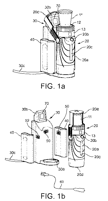
Fig. la is a perspective side view of a preferred
embodiment of the system according to the
invention, the system comprising a docking
station, a portable beverage preparation device
and a battery unit.
Fig lb is a perspective exploded assembly drawing of
the system as shown in figure la, the system
further comprising a car power connector.
Fig. 2 relates to a sectional side view of a preferred
embodiment of the portable beverage preparation
device in a storage or transport position.
Fig. 3a to 3c are sectional side views of the portable
beverage preparation device during provision of
a capsule into the brewing unit of the device.
Fig. 3d is a partial sectional side view of the device
in an operation state of the device, i.e. during
beverage production.
Fig. 4a is a perspective view from above of a preferred
embodiment of the beverage brewing unit of the
beverage preparation device
Fig. 4b is a perspective view from below of a preferred
embodiment of the beverage brewing unit of the
device.
CA 02945657 2016-10-13
WO 2015/173125 PCT/EP2015/060139
14
Fig. 4c is a perspective side view of a preferred
embodiment of a lid member for being connected
to the housing of the device.
Fig. 5a and 5b relate to a preferred embodiment of a
receptacle for being connected to the device
according to the invention, the receptacle
comprising selective openable valve means.
Fig. 5c relates to a bottom view of a preferred
embodiment of the receptacle as shown in figures
5a and 5b.
Detailed description of the figures
Figure la relates to a preferred embodiment of a system
according to the invention, the system comprises a portable
beverage preparation device 20, a docking station 30 and a
battery unit 40. The system may further comprise a power
cable such as a car power cable 60 (see figure lb) designed
for being selectively connected directly to the portable
device 20.
The portable device 20 is adapted for being electrically
and mechanically connected to a docking station 30 which is
electrically connected to the mains via a power cable 30c.
Thereby, the docking station comprises an AC/DC power
converter for converting the AC input current as provided
by the mains to preferably a DC output current of low
voltage. In particular, the AC/DC power converter of the
docking station 30 is adapted for converting an AC input of
110-220Volts, 2.2Ampere and 50-60Hz to an output current of
between 12-16Volts, preferably 15Volts at 12 Ampere.
CA 02945657 2016-10-13
WO 2015/173125 PCT/EP2015/060139
For this purpose, the portable device 20 comprises a single
multifunctional connector 51 preferably provided at a side
surface of a housing 20a of the device to which the
different power sources such as the docking station 30, a
5 battery unit 40 or a power cable 60 may be individually
connected.
For this purpose, the different power sources 30,40,60 of
the system are preferably equipped with the same electrical
10 connection means 50 and which are designed for being
selectively connected to the multifunctional connector 51
of the portable device 20. The connection means 50 are
preferably formed as male connection elements protruding to
a certain extent from the respective power sources
15 30,40,60. The multifunctional connector 51 is preferably
formed as female connection element.
The docking station 30 of the system is preferably designed
to operate as charging unit for at least one battery unit
40 of the system. Accordingly, the docking station 30
preferably comprises at least one dedicated connector 52 to
which the battery unit 40 may be connected electrically and
mechanically via its connection means 50. As shown in
figure lb, the docking station 30 is preferably designed to
support at least two battery units 40.
In a preferred embodiment as shown in figure la and lb, the
docking station 30 is preferably designed for connecting to
the portable device 20 and at least one, preferably at
least two battery units 40 at the same time. Therefore, the
electric connector 50 and the dedicated charging connectors
52 are arranged at different side-surfaces of the docking
station 30.
CA 02945657 2016-10-13
WO 2015/173125 PCT/EP2015/060139
16
The docking station 30 is preferably equipped with a
graphical user interface 70 designed for providing
information regarding the connected battery unit(s) 40 and
the portable device 20. In particular, a charging state of
the battery units 40 connected to the docking station 30
may be indicated. The user interface 70 may further be
designed for enabling control of the device 20 when being
connected to the docking station 30 and/or to provide
feedback information regarding the operational state of the
device 20.
The device 20 preferably comprises a housing 20a and a lid
member 13 arranged at a top portion of the housing 20a. The
lid member comprises an upper support surface 12 on which a
receptacle 11 may be arranged. The receptacle 11 and the
support surface 12 are preferably designed for enabling a
support of the receptacle 11 in an operating state of the
device as shown in figure la, as well as in a transport
state of the device as shown in figure lb.
The device 20 is preferably further equipped with a user
interface 20b. The user interface preferably comprises at
least a start/stop button for enabling a user to
selectively start and stop the beverage preparation by
means of the device. The device preferably further
comprises a window 20c for enabling a user to control the
liquid level in a liquid reservoir 8 (see figure 2) of the
device.
The device 20 preferably comprises an essentially vertical
cylindrical form. In an operating state, the device stands
on a preferably round front respective bottom surface 20d.
The bottom surface 20d and a support surface 30a of the
docking station 30 are preferably of conformal shape in
CA 02945657 2016-10-13
WO 2015/173125 PCT/EP2015/060139
17
order to guarantee a stable positioning of the device 20
when being connected to the docking station 30.
The device 20 preferably further comprises a handle 20e
that is pivotally arranged at the housing 20a and extends
from a central portion of the device towards an upper
portion thereon. The handle 20e preferably extends upwardly
beyond the support surface 12 of the lid member 13.
Thereby, the handle 20e is preferably shaped to support the
receptacle 11 during transport of the device such as e.g.
indicated in figure lb.
The handle 20e is further arranged to engage a dedicated
connection surface 30b of the docking station 30 when
placed on the support surface 30a thereof. Thereby, the
pivotally arranged handle 20e may be pivoted from an
essentially vertically extending position as shown in
figure lb to a slightly tilted orientation as indicated in
figure la, in which the handle 20e engages the connection
surface 30b. Accordingly, a stable positioning of the
portable device 20 at the docking station 30 is enabled.
Figure 2 relates to a sectional side view of the device 20
in a transport or storage mode thereof. Thereby, the
receptacle 11 is placed with its circumferential upper edge
llb on the support surface 12 of the device. The support
surface 12 may have dedicated engagement means such as a
circular protrusion enabling a clamping engagement with the
edge llb of the receptacle. As further indicated in the
figure, the handle 20e is arranged to press against the
bottom lla of the receptacle. Accordingly, the receptacle
11 may be safely retained between the handle 20e and the
support surface 12 of the device during transport and
storage.
CA 02945657 2016-10-13
WO 2015/173125 PCT/EP2015/060139
18
The device comprises a pump 7 such as a membrane pump, and
which is connected to a motor 7a. The pump 7 and/or the
motor 7a are preferably vibration-decoupled from the
housing 20, e.g. by means of springs 7b. The device further
comprises a liquid reservoir 8 that is in fluid connection
with the pump 7, and heating means 9. The heating means 9
are arranged within the liquid reservoir 8 and may comprise
a temperature sensor 9a. The heating means 9 are designed
for selectively heating the liquid volume contained within
the liquid reservoir 8 to a desired temperature. The device
preferably also comprises a control unit 9b connected to at
least the pump 7, the heating means 9 and the user
interface 20b.
The device further comprises a beverage brewing unit 5
preferably arranged at an upper portion of the device 20.
The brewing unit 5 preferably comprises a capsule injection
cage 5a that has a conformal shape to a capsule 10 to be
received therein. The injection cage 5a preferably has an
essentially bell-shaped form at which circumference linear
protrusions may be formed as indicated in the figure. These
may enable a facilitated removal of the capsule from the
cage 5a after beverage preparation.
The brewing unit 5 further comprises liquid inlet means 5b
connected to the liquid reservoir 8, the pump 7 and the
heating means 9 of the device. The brewing unit 5
preferably also comprises opening means Sc such as a
piercing member or cutting blade, which is adapted for
opening an inlet face 10a of a capsule 10 if placed within
the brewing unit 5.
An upper portion of the brewing unit 5 is preferably formed
by the removable lid member 13 which may be selectively
connected to the lower portion of the brewing unit 5. The
CA 02945657 2016-10-13
WO 2015/173125 PCT/EP2015/060139
19
lid member 13 comprises an outer circumferential lid
portion 13b and an inner central lid portion 13a which are
arranged freely rotatable relative to each other. The lid
member 13, in particular the inner central lid portion 13a
is equipped with opening means 15 arranged for opening an
outlet face 10b of the capsule 10 during the beverage
preparation process. The opening means 15 is preferably a
pyramidal plate comprising a horizontally arranged base
plate from which a plurality of small protrusions 15a are
directed downwards in direction of the outlet face 10b of
the capsule 10 (see figure 3c). In case of increasing
pressure within the capsule 10, an outlet face 10b thereof
will be urged against the pyramidal plate 15 and will then
tear at its protrusions 15a. The pyramidal plate 15 further
comprises small liquid channels 15b enabling a fluid flow
from the plate 15 towards a beverage dispensing means 6 of
the lid member 13.
The beverage dispensing means 6 are preferably comprised by
the lid member 13 and enable a fluid flow from the beverage
brewing unit 5 towards the receptacle 11. The dispensing
means 6 are arranged vertically above the brewing unit 5 of
the device. The dispensing means 6 comprise an injection
member 6a protruding from the support surface 12 for the
receptacle 11. The injection member 6a is preferably
arranged central at the support surface 12.
Figure 3a relates to a sectional side view of the device
when the lid member 13 was removed from the housing 20.
The beverage brewing unit 5 is preferably arranged movable
within the housing 20a. In particular, an external cage
block 5d (see also Figure 4b) holding the capsule injection
cage 5a is arranged movable within the device 20. The
injection cage 5a in preferably also arranged movable with
CA 02945657 2016-10-13
WO 2015/173125 PCT/EP2015/060139
respect to the cage block 5d, e.g. by means of a central
spring member 5f.
The cage block 5d holding the injection cage 5a is
5 preferably arranged vertically movable within the housing
20 by means of dedicated resilient means 5e such as e.g.
springs. The springs 5e are preferably homogenously
arranged at the circumference of the cage block 5d (see
also fig. 4b). The cage block 5d is preferably moveable
10 between a lower position as shown in figure 2 in case of
the lid member 13 being connected to the housing 20a and an
upper position as shown in figure 3a, when no lid member 13
is connected to the housing 20. In its upper position, a
fluid passage 16 between the injection cage 5a and the
15 liquid reservoir 8 is opened. In particular an annular
passage 16 is provided in the fluid communication from the
pump 7 to the injection cage 5a, which enables the
direction of fluid provided into the injection cage 5a to
the liquid reservoir 8. Thereby, dedicated guiding means
20 such as a liquid passage 16a and a guiding channel 16b are
in fluid communication with the annular passage 16 in order
to re-direct fluid provided from above in the injection
cage 5a to the liquid reservoir 8. The cage block 5d may
further comprise air exhausting means 25 (see fig. 4b)
designed for enabling a circulation of air between the
liquid reservoir 8 and the exterior of the housing 20.
According to such arrangement, the user may remove the lid
member 13 from the brewing unit 5 and may fill liquid such
as water directly into the capsule injection cage 5a for
re-filling the liquid reservoir 8. As an alternative to
such arrangement, a dedicated refill-aperture may be
provided at the housing 20a of the device.
Figure 3b relates to a sectional side view of the device 20
when a capsule 10 comprising beverage ingredients has been
CA 02945657 2016-10-13
WO 2015/173125 PCT/EP2015/060139
21
provided to the capsule injection cage 5a. The capsule 10
is preferably made from aluminium. However, the capsule may
as well be made from plastic or biodegradable material. The
capsule 10 preferably comprises a rotational-symmetric
truncated-cone shaped body having an inlet face 10a and an
outlet face 10b. The outlet face 10b is connected to a
circumferential flange-like rim portion 10c of the capsule.
Opening means 5c of the injection cage 5a are arranged to
open respectively pierce the inlet face 10a of the capsule
as depicted in figure 3b. When inserted into the device 20,
the capsule outlet face 10b is arranged at an uppermost
portion of the capsule. The inlet face 10a is arranged at a
lowermost portion of the capsule.
In case the lid member 13 is re-connected to the housing
20a as shown in figure 3c, the capsule 10 as previously
provided to the capsule cage 5a is enclosed in the brewing
unit 5 by means of the capsule cage 5a and the pyramidal
plate 15 of the lid member 13. Thereby, the pyramidal plate
15 presses against the upper outlet face 10b. The lid
member 13 may be connected to the housing 20a by means of a
helical path 13c enabling a translatory motion of the lid
member in downwards direction upon rotation of the outer
part 13b of the lid member 13 with respect to housing 20a.
Note that the liquid passage 16 between the capsule
injection cage 5a and the liquid reservoir 8 is (re-)closed
due to the external cage block 5d being pushed in a
downward direction as the lid member 13 is connected to the
housing 20a.
Further, upon (re-)connecting the lid member 13 with the
housing 20a, the inner lid portion 13a will interact with
rotation-prevention means 14 arranged at the beverage
brewing unit 5 and in particular at the external cage block
5d thereof (see also figure 4a), in order to prevent a
CA 02945657 2016-10-13
WO 2015/173125 PCT/EP2015/060139
22
relative movement of the inner lid portion 13a and the
capsule 10 arranged within the beverage brewing unit 5.
Thereby, the inner lid portion 13a may comprise dedicated
serrations or protrusions 13d (see fig. 4c) that interact
with the rotation-prevention means 14 of the brewing unit
5. Due to the inner portion 13a being freely rotationally
movable with respect to the outer portion 13b of the lid
member 13, a complete closure of the lid member 13 onto the
housing 20a is enabled. When the lid member 13 is then
disengaged from the housing 20a after the beverage
preparation, the central portion of the lid member 13 is
prevented from rotation with respect to the capsule 10 and
thus, the pyramidal plate 15 is prevented from further
rupturing respectively from destroying the outlet face 10b
of the capsule 10.
Figure 3d relates to an operating position of the beverage
preparation device 20 according to the invention. Thereby,
the receptacle 11 is connected to the beverage dispensing
means 6 of the device. This is obtained via valve means 17
arranged in a bottom portion lla of the receptacle 11 which
interact with the injection member 6a of the dispensing
means 6. In particular, the injection member 6a when being
connected to the bottom portion lla urges the valve means
17 upwardly in order to enable a fluid communication
between the injection member 6a and the interior of the
receptacle 11c.
The receptacle 11 preferably comprises magnetic connecting
members lld that are designed to interact with magnetic
connecting members 21 arranged at or below the support
surface 12 of the lid member 13 when the receptacle is
placed into the support surface 12. Accordingly, a magnetic
force will attract the receptacle 11 towards the support
surface 12 and thus, a stable connection between the
CA 02945657 2016-10-13
WO 2015/173125 PCT/EP2015/060139
23
receptacle 11 and the support surface 12 is ensured. The
magnetic members 11d within the receptacle 11 and/or the
lid member 13 may have an alternating polarity about the
circumference of the preferably circular arrangement (see
also fig. 5c). Accordingly, the user may rotate the
receptacle 11 in the support surface 12 in order to arrange
for an equal polarity being present between the receptacle
11 and the lid member 13, thus leading to a separating
force between the receptacle 11 and the support surface 12.
Hence, after beverage preparation, the user may rotate the
receptacle 11 to facilitate removal from the surface 12.
In case the user starts the beverage preparation by means
of the user interface 20b, the heating means 9 will heat
the liquid volume contained within the liquid reservoir 8
of the device. After a desired and predefined temperature
of the liquid is reached, the pump 7 will then be activated
in order to provide heated pressurized liquid, in
particular water, into the beverage brewing unit 5 via
dedicated tubing of the device. The liquid will be provided
to the capsule cage 5a, to the opening(s) created within
the inlet face 10a of the capsule 10 and thus to the
interior of the capsule 10. The pressure rise within the
capsule leads to a deformation of the outlet face 10b
against the pyramidal plate 15 due to which the outlet face
10b ruptures. A beverage resulting from the interaction of
the liquid with the ingredients contained in the capsule 10
will then be urged upwardly, against gravity, in direction
of the beverage dispensing means 6. Due to the established
connection between the dispensing means 6 and the interior
of the receptacle 11, the resulting beverage will be
provided through the bottom portion 11a of the receptacle
11 into the interior 11c thereof. The control unit 9b of
the device preferably stops the provision of liquid to the
brewing unit 5 after a predefined amount of liquid was
CA 02945657 2016-10-13
WO 2015/173125 PCT/EP2015/060139
24
provided thereto. Due to the direct provision of the
resulting beverage through the bottom portion 11a of the
receptacle, spilling of the beverage is effectively
prevented. It is noted that the fluid flow of the beverage
in particular from the brewing unit 5 to the interior 11c
of the receptacle 11 is preferably in a common direction,
in particular in a direction essentially opposite to
gravity. Accordingly, the fluid flow direction preferably
does not change from in particular the brewing unit 5 to
the receptacle 11.
Figure 4a relates to a perspective side view onto the
capsule cage block 5d and the capsule injection cage 5a
when being inserted into the housing 20a of the device. As
can be seen in the figure, serrations 14 are preferably
arranged about the circumference of an upper surface of the
capsule cage block 5d, which act as rotation-prevention
means when being engaged by the central portion 13a of the
lid member 13.
Figure 4b relates to a perspective side view onto the
capsule cage block 5d when being disconnected from the
housing 20a. The cage block 5d comprises springs 5e
arranged about the circumference of the block 5d and which
are designed to urge the cage block 5d in an upwards
direction in case the lid member 13 is not connected to the
housing 20a.
Figure 4c relates to perspective bottom view of the lid
member 13 in which the annular protrusions respectively
serrations 13d are indicated. The serrations 13d protrude
from a lower surface arranged at the circumference of the
pyramidal plate 15 and are designed to interact with
serrations 14 of the cage block 5d (see figure 4a). As
shown in the figure, an inner surface of the outer lid
CA 02945657 2016-10-13
WO 2015/173125 PCT/EP2015/060139
portion 13b comprises connecting members 13e designed to
interact with recessions 13c at the housing 20a of the
device (see fig. 3d) for connecting the lid member 13 to
housing 20a.
5
Figures 5a and 5b show the receptacle 11 designed for being
connected to device 20. Thereby, figure 5a shows the valve
means 17 of the receptacle in their open state and figure
5b relates to the valve means 17 being closed.
The valve means 17 preferably comprises an elastic part 23
that is extensible in vertical length when engaged by the
beverage injection member 6a of the beverage dispensing
means 6 of the device 20. Thereby, the elastic part 23
preferably comprises a lower part 23c that is fixed within
an essentially vertical aperture 24 provided in the bottom
portion 11a of the receptacle. Upon extension of the part
34 in an upwards direction due to the injection member 6a
(not shown in the figure) being introduced into a vertical
bore 23d of the part 23, an upper portion 23a of the part
23 extends beyond the vertical aperture 24 in the bottom
portion 11a of the receptacle, such that fluid
communication between the interior 11c of the receptacle 11
and the vertical bore 23d is enabled due to radially
extending bores 23b within the elastic part 23. When the
valve means 17 are disengaged from the protruding injection
member 6a, the elastic part 23 will retract and thus close
the radially extending bores 23b. Further, any liquid
provided to the interior 11c will exert a downwards-
directed force onto the part 23 in order to keep the valve
means 17 closed.
Figure Sc shows a bottom view of the receptacle 11, in
which the magnetic members 11d are indicated with their
different polarities 22a,22b as described above. In
CA 02945657 2016-10-13
WO 2015/173125 PCT/EP2015/060139
26
particular, the magnetic members 11d are provided in
circular arrangement about at the bottom portion 11a of the
receptacle 11. Thereby, the differing polarities 22a,22b
relating to North and South pole of a magnet are arranged
to alternate within the circular arrangement.
It is noted that although the present invention has been
described with reference to preferred embodiments thereof,
many modifications and alternations may be made by a person
having ordinary skill in the art without departing from the
scope of this invention which is defined by the appended
claims.