Note : Les descriptions sont présentées dans la langue officielle dans laquelle elles ont été soumises.
.
=.
ALIGNMENT TOOL, SYSTEM AND METHOD FOR THE CONNECTION OF WIND
TURBINE TOWER SEGMENTS
The present invention relates to an alignment system and an alignment tool for
use in
the connection of wind turbine tower segments during the construction of a
wind turbine
tower and to a method for the alignment of adjacent segments of a wind turbine
tower.
The increasing demand for wind energy may be met both by building more wind
parks and by building wind parks capable of generating more energy per
turbine.
Generating more energy per turbine requires wind turbines with larger
generators, which in
turn need larger blades to capture more energy from the incident wind. Such
turbines also
require wider and taller towers to support the blades, nacelle and other
components. The
increasing physical dimensions of modern wind turbine towers lead to
difficulties in
transporting the tower from the manufacturing site to the installation site
where the wind
turbine is to be constructed. This is particularly true if the wind turbine
tower or components
of the wind turbine tower are to be transported by road, for example on the
trailer of a truck,
causing potential disruption to other road users.
Wind turbine towers may therefore be transported as a series of prefabricated
parts
which are assembled into the tower at the installation site. Although the use
of prefabricated
tower parts makes transport easier, additional overhead is placed on the pre-
transport and
assembly processes as a result of the larger number of component parts that
need to moved
and handled. Such a tower is described in WO 2004/083633, filed on 19 March
2003.
Further, due to variations in individual manufacturing processes prefabricated
sections may
not always fit together as readily as would be desired, resulting in more
intensive labour at
the construction site. In addition, the prefabricated parts may need to be
assembled into
towers that taper from a wider base to a smaller diameter towards the top.
This means that
the prefabricated parts may be of different physical dimensions to one another
and thus
require more complex handling and transport.
Wind turbine towers may be constructed from a plurality of steel shells joined
together by means of bolted or welded joints. The plurality of steel shells
are circular in cross
section and may have diameters that are greater for the shells used at the
base section of
the tower and smaller for sections used at the top. This gives the tower a
tapered shape
with a wider base, providing a structure strong enough to support the nacelle
and the
components housed within it, and to resist the lateral forces from the wind
and rotor blades.
The steel shells are often manufactured at a tower production site and joined,
such as by
1
CA 2945861 2018-01-25
=
welding, together into cylindrical sections of the tower for transport to a
construction or
installation site. The shells can also be frusto-conical in shape.
A cylindrical section of the tower may therefore be made up of a plurality of
steel
shells. The cylindrical sections of the tower may be cut into segments for
ease of transport
as described in WO 2004/083633 Al, filed on 19 March 2003. Transport may
potentially be
over both land and sea.
The segments are secured to one another to form a tower section by means of
vertical flanges located along the interior of the segments at their vertical
edges. The
flanges of adjacent segments can be joined using bolts inserted through bolt
holes in the
flanges. Flanges are also attached to the periphery of the open ends of the
cylindrical
section so the tower sections, once mounted on top of each other, can be
joined together.
Similarly, the flanges of adjacent segments and sections are joined using
bolts inserted
through bolt holes in the flanges.
Once the cylindrical tower sections are assembled into a tower, the flanges
attached
to the open ends of the cylindrical sections will be orientated horizontally,
and will be joined
to corresponding flanges on the neighbouring sections. In use, the interior
longitudinal
flanges will be orientated vertically. The terms "horizontal flange" and
"vertical flange" will
therefore be used herein to distinguish the two types of flanges from one
another.
The process of first forming a complete tower section and subsequently cutting
the
cylindrical section into tower segments assists the tower segments in fitting
together properly
when they are reassembled at the installation site. This technique is
therefore in contrast to
methods where individual segments are separately manufactured and then
assembled into a
cylindrical section for the first time at the installation site. When the
tower segments are
reassembled into the cylindrical sections, the longitudinal edges of the tower
segments are
joined along the vertical flanges provided on the interior of the tower
section. Alternatively,
the tower segments can be manufactured as single parts without cutting them
out from a
complete tower section.
The use of the word "vertical" with regard to the flanges is to indicate their
orientation
once installed in the tower, and is not therefore intended to be used in a
limiting way with
regard to the method of production or assembly. As will be explained below,
the handling
and reassembly processes may be more conveniently carried out while the
flanges are laid
horizontally.
2
CA 2945861 2018-01-25
It
CA 02945861 2016-10-14
WO 2015/161855 PCT/0K2015/050096
Each of the vertical flanges provided on the interior of the tower segments
will
typically be provided with a plurality of spaced apart holes along the length
of the flange, for
receiving bolt fasteners to connect the vertical flange to the corresponding
flange of the
adjacent segment. During the reassembly method, the adjacent tower segments
must be
brought together so that the vertical flanges are aligned with each other,
with the plurality of
holes substantially aligned opposite each other so that a plurality of bolts
may be passed
through the holes of the flanges to connect them to each other.
The vertical flanges will typically be welded onto the inside of the tower
segments
and may be formed of several connected sections. The vertical flanges may not,
therefore,
be completely straight along the entire length, which may make the alignment
of the flanges
more difficult. There will also typically be at least a small degree of
deformation of the
vertical flanges and the tower segments due to the large size and weight of
the components.
Furthermore, the large size of the tower segments may make it difficult to
bring the adjacent
tower segments together with enough accuracy that the flanges are sufficiently
aligned. If
the vertical flanges are misaligned, the corresponding connection holes in the
flanges will not
be at the same level as each other and the mounting of the connection bolts in
the holes will
therefore not be possible.
It would therefore be desirable to provide a system and method for
facilitating the
alignment of the vertical flanges during reassembly of the tower segments so
that the
connection of adjacent flanges can be carried out more accurately and more
efficiently. It
would further be desirable if such a system and method could be provided that
ensures
minimal damage to the vertical flanges of the tower segments or the tower
segments
themselves.
SUMMARY OF THE INVENTION
According to a first aspect of the invention there is provided a wind turbine
tower
segment for forming a cylindrical section of a wind turbine tower, the
cylindrical section
constructed from a plurality of tower segments connected along their
respective longitudinal
edges, wherein the tower segment comprises a first vertical flange on the
interior thereof,
proximate a longitudinal edge and further comprises an alignment tool mounted
on the first
vertical flange for the alignment of the first vertical flange of the tower
segment with a second
vertical flange of an adjacent tower segment during the connection of the
adjacent tower
segments to form the cylindrical section.
The alignment tool of the tower segment of the invention comprises: mounting
means
connecting the alignment tool to a portion of the first vertical flange of the
tower segment;
and a longitudinal alignment head comprising a front portion extending in a
forwards
3
SUBSTITUTE SHEET (RULE 26)
CA 02945861 2016-10-14
WO 2015/161855 PCT/0K2015/050096
direction from the mounting means over the longitudinal edge of the tower
segment. The
front portion comprises a lower guiding surface adapted to abut with a top
guiding edge of
the second vertical flange of the adjacent tower segment and to guide the
alignment head
over the top guiding edge of the second vertical flange as the first and
second vertical
flanges are brought towards each other during connection of the adjacent tower
segments.
The tower segment according to the invention preferably comprises a main body
portion, which will typically be formed of a steel sheet having a curved
profile. The tower
segment comprises two opposed longitudinal edges, which will be substantially
straight and
vertical in the assembled tower section. A vertical flange is provided at a
distance from a
first longitudinal edge and this flange will be connected to a corresponding
vertical flange on
the adjacent tower segment. The flange is preferably formed of steel and is
preferably
welded to the inner surface of the tower segment. The flange may be formed of
a single
part, or a plurality of connected parts. An alignment tool as described in
more detail below is
mounted on the vertical flange. The tower segment will typically further
comprise a second
vertical flange proximate the opposite longitudinal edge and this second
vertical flange may
additionally include an alignment tool mounted thereon for the alignment of
the tower
segment with an adjacent tower segment on the opposite side.
The tower segment according to the invention will be connected along each of
its
longitudinal edges to corresponding tower segments to make up a cylindrical
tower section,
as described above. The tower sections will then be assembled vertically by
connecting
them along their horizontal edges to form a wind turbine tower.
According to a second aspect of the invention there is provided an alignment
system
for aligning a pair of vertical flanges for the connection of the longitudinal
edges of adjacent
tower segments of a cylindrical section of a wind turbine tower, wherein a
vertical flange is
provided on the interior of each tower segment, proximate the respective
longitudinal edge.
The alignment system comprises: an alignment tool for mounting on a first
vertical flange of
a first tower segment and a guiding bracket for mounting on a second vertical
flange of a
second tower segment substantially opposite the alignment tool, wherein the
second bracket
comprises a top guiding edge adapted to sit above the top edge of the second
vertical flange
during use.
The alignment tool of the alignment system according to the second aspect of
the
invention comprises: mounting means for connecting the alignment tool to a
portion of the
first vertical flange of the first tower segment; and a longitudinal alignment
head comprising a
front portion extending in a forwards direction from the mounting means. The
front portion
4
SUBSTITUTE SHEET (RULE 26)
CA 02945861 2016-10-14
WO 2015/161855 PCT/0K2015/050096
comprises a lower guiding surface adapted to abut with the top guiding edge of
the guiding
bracket mounted on the second vertical flange and to guide the alignment head
over the top
guiding edge of the guiding bracket as the first and second vertical flanges
are brought
towards each other during connection of the first and second tower segments.
According to a third aspect of the invention there is provided an alignment
system for
aligning a pair of vertical flanges for the connection of the longitudinal
edges of adjacent
tower segments of a cylindrical section of a wind turbine tower, wherein a
vertical flange is
provided on the interior of each tower segment, proximate the respective
longitudinal edge,
the alignment system comprising a first alignment tool for mounting on a first
vertical flange
of a first tower segment and a second alignment tool for mounting on a second
vertical
flange of a second tower segment substantially opposite the first alignment
tool.
Each of the first and second alignment tools of the alignment system according
to the
third aspect of the invention comprises: mounting means for connecting the
alignment tool to
a portion of the vertical flange of the respective tower segment; a top
guiding edge adapted
to sit above the top edge of the corresponding vertical flange during use; and
a longitudinal
alignment head comprising a front portion extending in a forwards direction
from the
mounting means towards the opposite alignment tool. The front portion
comprises a lower
guiding surface adapted to abut with the top guiding edge of the opposite
alignment tool and
to guide the alignment head over the top guiding edge of the opposite
alignment tool as the
alignment tools are brought towards each other during connection of the first
and second
tower segments.
According to a fourth aspect of the invention there is provided an alignment
tool for
use in aligning a pair of vertical flanges for the connection of the
longitudinal edges of
adjacent tower segments of a cylindrical section of a wind turbine tower,
wherein a vertical
flange is provided on the interior of each tower segment, proximate the
respective
longitudinal edge. The alignment tool comprises: mounting means for connecting
the
alignment tool to a portion of a vertical flange of a tower segment; and a
longitudinal
alignment head for aligning the vertical flange with an opposing vertical
flange of an adjacent
tower segment, the alignment head comprising a front portion extending in a
forwards
direction from the mounting means. The front portion comprises a lower guiding
surface
adapted to abut with a top guiding edge of the opposing vertical flange or a
bracket mounted
thereon and to guide the alignment head over the top edge of the opposing
flange or bracket
as the vertical flanges are brought towards each other during connection of
the adjacent
tower segments.
5
SUBSTITUTE SHEET (RULE 26)
CA 02945861 2016-10-14
WO 2015/161855 PCT/0K2015/050096
According to the invention there is further provided the use of an alignment
system or
alignment tool according to the invention, as defined above, during the
construction of a wind
turbine tower formed from a plurality of connected tower segments.
In the following description, any discussion of the alignment tool or tools of
the
alignment systems of the present invention should also be considered as being
applicable to
the alignment tool of the present invention and the alignment tool of the
tower segment of
the present invention, and vice versa.
As described in more detail below, the alignment system or tool according to
the
present invention can advantageously be mounted on the existing vertical
flanges of the
tower segments, without the need for any modification of the flanges or the
tower segments.
The mounting of the alignment tools can be carried out simply and conveniently
prior to the
reassembly process and the alignment tools can be readily removed from the
tower
segments once the connection of the pair of vertical flanges is complete.
The alignment tools and systems of the present invention use the alignment
head of
the alignment tool (or tools) to guide the vertical flanges towards each other
and to align the
level of the vertical flanges as they are brought together so that the holes
in the flanges are
brought to the same level as each other for insertion of the connection bolts.
The lower
guiding surface of the alignment head of the tool is adapted to abut with a
top guiding edge
provided on the opposite vertical flange and to slide over the top guiding
edge, thereby
guiding the alignment head over the top guiding edge. In this way, the
alignment system
guides the flanges towards each other at the same level. According to the
first aspect of the
invention, the alignment head is adapted to engage with the top edge of the
opposite vertical
flange. In the alignment systems of the second and third aspects of the
invention, the
alignment head is instead adapted to engage with a top guiding edge provided
on a
complementary guiding bracket or alignment tool, respectively, rather than the
top edge of
the flange itself. Any direct contact between the alignment head and the
vertical flanges is
therefore avoided, thus avoiding potentially damage to the vertical flanges
during the
reassembly process.
Once the vertical flanges are brought together to the desired separation, the
alignment tool or tools act to stabilise the flanges at the same level whilst
the connection of
the flanges is carried out.
The alignment systems according to the second and third aspects of the present
invention comprise a pair of complementary components which act together to
bring about
6
SUBSTITUTE SHEET (RULE 26)
CA 02945861 2016-10-14
WO 2015/161855 PCT/0K2015/050096
the alignment of the pair of vertical flanges. As described above, the pair of
components
may include a single alignment tool and a guiding bracket, or a pair of
alignment tools. In
either case, the components are preferably mounted on the vertical flanges to
be connected
at corresponding vertical levels such that the components are opposite to each
other and
can engage with each other as the longitudinal edges of the tower segments are
brought
together. Preferably, alignment systems according to the invention comprise a
plurality of
pairs of components, spaced apart along the length of the tower segments such
that the
alignment of the vertical flanges can be effected along the full length. Each
tower segment
will therefore incorporate a plurality of alignment tools or guiding brackets
mounted at
spaced apart intervals along the respective vertical flange.
In certain embodiments of the invention, one or more alignment tools may be
provided on both of the vertical flanges but with the alignment tools offset
from each other in
the longitudinal direction so that the alignment tools are not provided
opposite to each other
in pairs. In this case, each alignment tool may engage with the top edge of
the opposite
vertical flange, as in the first aspect of the invention, or with the top
guiding edge of an
opposed guiding bracket, as in the second aspect of the invention.
The constituent parts of the alignment tools will now be described in more
detail. The
following description applies to the alignment tools of all aspects of the
invention. It should
be assumed that in the alignment systems of the third aspect of the present
invention
comprising a pair of alignment tools, the first and second alignment tools of
each pair are of
a corresponding size and construction to each other.
As described above, each alignment tool is formed of mounting means for
connecting
the tool to the vertical flange and an alignment head for bringing about the
alignment of the
vertical flanges of adjacent tower segments.
The mounting means of the alignment tool of the present invention is adapted
for
fixture to the interior vertical flange of a tower segment and is preferably
adapted to be
connected to the existing holes provided in the flange using one or more
conventional
fasteners. No modification to the construction of the vertical flange or the
tower segment is
therefore required in order to implement the alignment system.
The mounting means may take any suitable form which enables the alignment tool
to
be effectively mounted on the vertical flange. Preferably the mounting means
comprises an
attachment bracket adapted to receive one or more fasteners for the connection
of the
attachment bracket against the corresponding vertical flange. The alignment
head is
preferably mounted on the attachment bracket. Where the alignment system
comprises a
pair of alignment tools, as in the third aspect of the invention, the
attachment bracket
7
SUBSTITUTE SHEET (RULE 26)
CA 02945861 2016-10-14
WO 2015/161855 PCT/0K2015/050096
preferably provides at least a part of the top guiding edge with which the
alignment head of
the opposite tool engages during use.
The attachment bracket may be attached directly to the flange, or in some
cases an
intermediate plate or layer may be inserted between the attachment bracket and
the flange.
Preferably, the attachment bracket comprises one or more holes for aligning
with the
holes on the corresponding vertical flange to enable suitable fasteners to be
fitted.
Preferably, the attachment bracket is connected to a plurality of the holes of
the vertical
flange using a plurality of fasteners. For example, in the specific embodiment
described
below, the attachment bracket comprises three holes for connecting the bracket
to three
corresponding holes in the vertical flange. Where a plurality of connection
holes is provided
in the attachment bracket, the holes may be adapted to receive a variety of
suitable
fasteners, as would be known to the skilled person. For example, one or more
holes on the
attachment bracket may be adapted to receive a conventional bolt fastener,
such as those
used to connect the opposed vertical flanges. Alternatively or in addition,
one or more holes
on the attachment bracket may be adapted to receive a non-threaded pin or
bolt. In certain
preferred embodiments, a combination of bolt fasteners and non-threaded pins
is used in
order to facilitate the removal of the alignment tools after the connection of
the vertical
flanges.
Preferably, the attachment bracket comprises one or more elongate slotted
holes to
receive one or more fasteners for the connection of the bracket against the
vertical flange,
each elongate slotted hole extending in the longitudinal direction of the
flange. The use of
slotted holes enables the alignment tool to be adapted to fit to vertical
flanges having
different hole spacings and may facilitate the mounting of the tool for tower
segments of
different sizes. Preferably, at least one circular hole is provided in
combination with the
elongate slotted holes, for example in the centre of the attachment bracket,
in order to
secure the longitudinal position of the attachment bracket along the vertical
flange.
Where the attachment bracket provides a top guiding edge for engaging with the
alignment head of an opposite alignment tool, as described above, the size and
shape of the
attachment bracket and the position of the holes for receiving the one or more
fasteners for
connection to the vertical flange may be adapted such that when the alignment
tool is in
place on the vertical flange, the top guiding edge of the attachment bracket
is positioned
above the level of the top edge of the vertical flange. This is to ensure that
the lower guiding
surface of the alignment head of the opposite alignment tool is able to slide
over the top
guiding edge of the opposite attachment bracket and not come into contact with
the vertical
flange. As discussed above, this is to avoid any damage to the vertical
flanges of the tower
8
SUBSTITUTE SHEET (RULE 26)
CA 02945861 2016-10-14
WO 2015/161855 PCT/0K2015/050096
segments. Preferably, the top guiding edge of the attachment bracket is
substantially
straight.
The attachment bracket may take any suitable form. In
certain preferred
embodiments of the invention, the attachment bracket comprises an attachment
plate, on
which the alignment head is mounted. The attachment plate is typically flat
and longitudinal
in shape and in use is connected against a portion of the vertical flange,
with the longitudinal
axis of the attachment plate substantially aligned with the longitudinal axis
of the vertical
flange. Where required, the top edge of the attachment plate provides the top
guiding edge.
In certain embodiments, the attachment bracket may be provided with a lip or
flange
at the top end, which is adapted to overlie the top edge of the vertical
flange of the tower
segment when the alignment tool is in position, thereby further increasing the
level of
protection of the vertical flange in the region of the alignment tool. The
lower surface of the
additional lip or flange is preferably substantially flush with the top edge
of the vertical flange,
so that the alignment tool can be additionally supported on the additional
flange or lip. The
lip or flange may be an integral part of the attachment bracket or may be
fitted as a separate
part at the top edge of the attachment bracket. The top edge of the lip or
flange is preferably
substantially flush with the top edge of the attachment bracket and the top
edge therefore
preferably forms a part of the top guiding edge, where required, in
combination with the top
edge of the attachment bracket.
The longitudinal alignment head of the alignment tool of the present invention
is
connected to or integrated with the mounting means such that the connection of
the
mounting means to the vertical flange also fixes the position of the alignment
head relative to
the flange. Where the mounting means comprises an attachment bracket as
described
above, the alignment head is preferably mounted at the top edge of the
attachment bracket.
The alignment head may be fixedly mounted to the attachment bracket, for
example by
welding, such that there is substantially no relative movement of the
alignment head and the
attachment bracket. Alternatively, the alignment head may be pivotally mounted
at the top
edge of the attachment bracket to enable a certain degree of pivotal movement
of the
alignment head relative to the attachment bracket, about the top edge of the
alignment head.
The alignment head may be mounted directly or indirectly on the attachment
bracket
or alternative mounting means using any suitable means, as would be known to
the skilled
person. The skilled person will appreciate that the way in which the alignment
head is
mounted will depend to some extent on the shape and form of the alignment head
and the
mounting means. In the specific embodiment described below, the alignment head
comprises a cut out at a position along the bottom edge, which is seated over
the top edge
9
SUBSTITUTE SHEET (RULE 26)
CA 02945861 2016-10-14
WO 2015/161855
PCT/0K2015/050096
of the attachment bracket. The alignment head is then held in place using
suitable means
such as welding or bolting.
Preferably, where the mounting means comprises an attachment bracket as
described above, the alignment head is mounted adjacent a first end of the top
edge of the
attachment bracket. For embodiments including a pair of alignment tools, this
positioning of
the alignment head at one end of the attachment bracket provides sufficient
space along the
remainder of the top edge for the sliding engagement with the alignment head
of the
opposite alignment tool. Typically, the alignment tools will be mounted
opposite to each
other such that the alignment head of each tool slides over the top edge of
the attachment
bracket of the opposite alignment tool at the opposite end of the top edge to
the end at
which the alignment head is mounted. This arrangement ensures that the
alignment heads
are able to slide freely over the opposite alignment tools without the risk of
interference or
collision of the tools with each other.
Preferably, the longitudinal alignment head is mounted such that the
longitudinal axis
of the alignment head is substantially perpendicular to the longitudinal axis
of the vertical
flange. The perpendicular arrangement of the alignment head enables the
alignment head
to remain in substantially the same longitudinal position relative to the
opposite vertical
flange as the alignment head is guided over the top edge of the opposite
flange, bracket or
tool.
The alignment head comprises a front portion extending in a forwards direction
from
the mounting means. The front portion therefore extends from the mounting
means over the
longitudinal edge of the tower segment towards the opposite vertical flange.
The front portion of the alignment head provides a lower guiding surface which
is
adapted to slide over the top edge of the opposite flange or a bracket or tool
mounted
thereof, as the vertical flanges are brought together, thereby guiding the
alignment head
over the top edge. The lower guiding surface is therefore preferably
relatively smooth and
preferably has a substantially continuous shape. The lower guiding surface may
be
substantially straight or may be curved, or may include straight portions and
curved portions.
Preferably, the lower guiding surface curves or slopes in a downwards
direction
moving along the front portion from the distal end thereof along at least a
part of the length
of the front portion towards the attachment bracket. The vertical distance
between the top
edge of the front portion and the lower guiding surface therefore increases
with increasing
distance from the distal end of the front portion, along at least the section
of the front portion
proximate the distal end.
SUBSTITUTE SHEET (RULE 26)
CA 02945861 2016-10-14
WO 2015/161855 PCT/0K2015/050096
The "distal end" refers to the free end of the front portion furthest from the
mounting
means. The distal end will typically be the first part of the front portion to
come into contact
with the opposite flange, bracket or tool during the alignment process. The
downwards
sloping of the lower guiding surface from the distal end facilitates the
initial abutment of the
alignment head and the opposite top guiding edge and helps to reduce the
impact of the
abutment of the alignment tool on the vertical flanges. The sloping shape
proximate the
distal end also ensures that the initial sliding of the alignment head over
the opposite guiding
edge is as smooth as possible and that unnecessary loading of the alignment
tool(s) and the
vertical flanges is avoided.
The lower guiding surface may slope downwards from the distal end in a
substantially straight line, or in a curved manner. Preferably, the lower
guiding surface of the
alignment head comprises a convexly curved portion proximate the distal end of
the
alignment head. Particularly preferably, the convexly curved portion of the
lower guiding
surface extends to the top edge of the front portion at the distal end of the
alignment head to
provide the front portion with a curved distal end. This further reduces the
impact of the
initial abutment of the alignment head with the opposite guiding edge compared
with a front
portion having a blunter shape.
Preferably, the lower guiding surface of the front portion of the alignment
head
comprises a substantially flat, horizontal portion extending continuously from
the sloping
portion towards the attachment bracket. After the initial sliding of the
alignment head over
the top guiding edge of the opposite alignment tool, the horizontal portion of
the lower
guiding surface enables the relative levels of the opposite flanges to be
fixed and maintained
such that the levels remain the same with any further movement of the flanges
towards each
other.
Preferably, the lower guiding surface comprises an abutment between the distal
end
of the front portion of the alignment head and the mounting means, for
limiting the sliding
movement of the alignment head over the opposite guiding edge. The abutment
will typically
take the form of a shoulder or step in the lower guiding surface that projects
in a downwards
direction from the surface. As the vertical flanges are brought together, the
alignment head
will slide over the opposite guiding edge until the abutment in the lower
guiding surface
abuts with the opposite guiding edge. At this point, further movement of the
vertical flanges
towards each other will be substantially prevented. The position of the
abutment in the lower
guiding surface may be adapted depending on the desired separation of the
vertical flanges
for bolting.
11
SUBSTITUTE SHEET (RULE 26)
CA 02945861 2016-10-14
WO 2015/161855 PCT/0K2015/050096
In certain embodiments, an abutment in the lower guiding surface may be
unnecessary or may be provided as a precautionary measure rather than to
define the
separation distance of the vertical flanges, for example, where it is intended
to bring the
vertical flanges together and into contact with each other for bolting, with
no separation
between them.
Preferably, the alignment head further comprises a rear portion extending
backwards
from the mounting means, (i.e. back towards the main body of the tower
segment), and
adapted to engage with the inner surface of the respective tower segment
during use. The
rear portion may itself be adapted for direct contact with the inner surface
of the tower
segment. Alternatively, the rear portion may be adapted to receive an
additional component
for engagement with the inner surface. For example, the rear portion of the
alignment head
is preferably adapted to receive a screw member or hydraulic member having a
distal end
adapted to engage with the inner surface of the respective tower segment
during use.
The rear portion therefore preferably includes one or more holes, annular
channels,
rings or other suitable means to receive a screw member or hydraulic member
which passes
through the rear portion and into contact with the inner surface of the tower
segment. The
screw member or hydraulic member passing through the rear portion of the
alignment head
works together with the mounting means to secure the position of the alignment
tool relative
to the corresponding vertical flange. The screw member or hydraulic member in
the rear
portion of the alignment head may also act to brace the alignment head against
the inner
surface of the tower segment. This minimises as far as possible any torque on
the vertical
flange from the alignment tool, thereby reducing the risks of damage to the
vertical flanges
during use of the alignment system.
Preferably, the rear portion of the alignment head is adapted to receive an
adjustable
screw member or hydraulic member which can be adjusted to bring the distal end
thereof
into contact with the inner surface of the tower segment. This enables the
alignment tool to
be adjusted to engage with tower segments of different sizes and
circumferences. In
certain embodiments, the adjustable screw member or hydraulic member may also
be
adapted for adjusting the height and angle of the alignment head relative to
the vertical
flange when the alignment tool is installed on the vertical flange. This
enables the alignment
tool to be adjusted to the appropriate height and angle depending on, for
example, the
dimensions of the vertical flange and/or the diameter of the corresponding
tower section.
When the screw member or hydraulic member is in place through the rear portion
of
the alignment head, the distal end of the screw member or hydraulic member
preferably
contacts the inner surface of the tower segment to provide the engagement of
the rear
portion of the alignment head with the inner surface. The distal end of the
screw member or
12
SUBSTITUTE SHEET (RULE 26)
CA 02945861 2016-10-14
WO 2015/161855
PCT/0K2015/050096
hydraulic member may directly contact the inner surface of the tower segment.
However,
more preferably, resilient means are provided between the distal end of the
screw member
or hydraulic member and the inner surface of the tower segment in order to
minimise
damage to the inner surface. For example, in certain preferred embodiments the
screw
member or hydraulic member comprises a resilient cap, such as a rubber cap, at
the distal
end thereof.
The alignment tool may further comprise a screw member or hydraulic member
mounted in the rear portion of the alignment head. In such embodiments, the
screw member
or hydraulic member for providing engagement between the alignment head and
the inner
surface of the tower segment is integrated into the alignment tool.
The front portion and the rear portion of the alignment head are preferably
integrally
formed with each other in a single part, but may alternatively be formed of
two separate
parts which are connected to each other directly, or through the mounting
means.
In certain embodiments of the invention comprising a pair of alignment tools,
means
may be provided to clamp the first and second alignment tools of the alignment
system
together during use. In this way, the first and second alignment tools could
be used not only
to align the level of the vertical flanges but additionally to provide a
clamping arrangement to
adjust and maintain the distance between the vertical flanges. For example,
the first and
second alignment tools may be adapted to be connected together such that the
attachment
brackets of the tools form the opposed jaws of a vice arrangement, wherein the
vice
arrangement may be used to draw the attachment bracket towards each other.
The alignment tools of the present invention may be formed from a variety of
suitable
materials, which would be known to the skilled person. A suitable material
should provide
the requisite rigidity and strength to enable the alignment tool to function
as described. An
example of a suitable and preferred material is steel.
In the alignment systems according to the second aspect of the present
invention, a
first alignment tool is used in conjunction with a guiding bracket on the
opposite flange.
Where a guiding bracket is used on the opposite flange, the guide bracket may
take a similar
form to that described above with reference to the attachment bracket for the
alignment tool.
The guiding bracket is preferably adapted to be connected to the vertical
flange as described
above for the attachment bracket, i.e. by means of suitable holes for
receiving fasteners to
connect the guiding bracket to the existing holes on the vertical flange. In
certain preferred
embodiments, the guiding bracket comprises a guiding plate with an arrangement
of holes
for receiving one or more fasteners. The guiding bracket is adapted such that
once fixed in
place on the vertical flange, the top edge of the guiding bracket sits above
the top edge of
13
SUBSTITUTE SHEET (RULE 26)
CA 02945861 2016-10-14
WO 2015/161855
PCT/0K2015/050096
the vertical flange to provide a top guiding edge with which the alignment
head of the first
alignment tool engages during use. The top guiding edge is preferably
substantially straight.
The guiding bracket should be mounted at substantially the same vertical level
as the
first alignment tool so that the alignment head of the tool abuts with the top
guiding edge of
the bracket as the vertical flanges are brought together. Several alignment
tools may be
used along the length of a tower segment, with a corresponding number of
guiding brackets
provided on the opposite vertical flange. The spacing of the alignment tools
and brackets
may be altered as required.
Similarly, where the alignment system of the invention includes first and
second
alignment tools, the alignment tools should be mounted at substantially the
same vertical
level as each other so that the alignment head of each tool is mounted
opposite the top
guiding edge of the opposite tool. The alignment tools may be mounted on the
vertical
flanges independently from each other, provided the corresponding pairs of
tools are
mounted at the same vertical level as each other. Several pairs of alignment
tools may be
used along the length of each segment and the spacing of the pairs of tools
may be altered
as required.
According to the invention there are provided methods for the alignment of the
vertical flanges of adjacent segments of a cylindrical section of a wind
turbine tower during
the connection of the longitudinal edges of the adjacent segments, each
segment comprising
a vertical flange on the interior of the segment, proximate the respective
longitudinal edge.
A first method according to the invention comprises the steps of:
installing an alignment system according to the second aspect of the
invention, as
defined above, into the adjacent tower segments by mounting an alignment tool
on the
vertical flange of the first tower segment and mounting a guiding bracket on
the vertical
flange of the second tower segment at a corresponding vertical position to the
first alignment
tool;
arranging the tower segments with the respective longitudinal edges adjacent
to each
other such that the alignment head of the alignment tool is abutting the top
guiding edge of
the opposite guiding bracket to align the levels of the vertical flanges; and
adjusting the tower segments to bring the longitudinal edges towards each
other
such that the alignment head the alignment tool is guided over the top guiding
edge of the
opposite guiding bracket until the vertical flanges are a predetermined
distance from each
other.
A second method according to the invention comprises the steps of:
14
SUBSTITUTE SHEET (RULE 26)
CA 02945861 2016-10-14
WO 2015/161855
PCT/0K2015/050096
installing an alignment system according to the third aspect of the invention,
as
defined above, into the adjacent tower segments by mounting a first alignment
tool on the
vertical flange of the first tower segment and mounting a second alignment
tool on the
vertical flange of the second tower segment;
arranging the tower segments with the respective longitudinal edges adjacent
to
each; and
adjusting the tower segments to bring the longitudinal edges towards each
other
such that the alignment head of each alignment tool is guided over the top
guiding edge of
the opposite alignment tool until the vertical flanges are a predetermined
distance from each
other.
Preferably, the first and second alignment tools are mounted at a
corresponding
longitudinal position to each other with the respective alignment heads offset
from each
other in the longitudinal direction such that the lower guiding surface of the
alignment head
of each alignment tool abuts the top guiding edge of the opposite alignment
tool to align the
levels of the vertical flanges.
A third method according to the invention comprises the steps of:
installing an alignment tool according to the invention, as defined above, on
the
vertical flange of the first tower segment;
arranging the tower segments with the respective longitudinal edges adjacent
to each
other such that the alignment head of the alignment tool is abutting the top
edge of the
opposite vertical flange of the adjacent tower segment to align the levels of
the vertical
flanges; and
adjusting the tower segments to bring the longitudinal edges towards each
other
such that the alignment head of the alignment tool is guided over the top edge
of the
opposite vertical flange until the vertical flanges are a predetermined
distance from each
other.
During each alignment method, the (or each) alignment tool is first brought
into initial
contact with the opposite top guiding edge, which may be provided on the
opposite
alignment tool, guiding bracket, or flange, depending on the method. The tower
segments
are then adjusted more accurately to bring the longitudinal edges of the
adjacent segments,
and therefore the (or each) alignment tool and the corresponding guiding edge,
towards
each other. During this adjustment step, the alignment head of the (or each)
alignment tool
will slide over the top guiding edge of the opposite flange, tool or bracket
and the alignment
tool or tools will act to guide the flanges and to align the levels of the
vertical flanges relative
SUBSTITUTE SHEET (RULE 26)
CA 02945861 2016-10-14
WO 2015/161855 PCT/0K2015/050096
to each other. In this way, the holes of the vertical flanges will be aligned
with each other in
opposing pairs along the length of the vertical flanges. Once the flanges are
brought
together to the desired separation distance, bolt fasteners can then be passed
through the
respective pairs of holes to connect the vertical flanges in the conventional
manner.
Preferably, the step of mounting the (or each) alignment tool on the
respective
vertical flange comprises: connecting the mounting means of the alignment tool
to the
vertical flange using one or more fasteners, wherein the mounting means are
connected
such that the front portion of the alignment head extends forwards towards the
longitudinal
edge of the tower segment. Where the alignment head includes a rear portion,
as described
above, the method further comprises inserting a screw member or hydraulic
member
through the rear portion of the alignment head of the alignment tool; and
adjusting the screw
member or hydraulic member in the rear portion of the alignment head to engage
the distal
end of the screw member or hydraulic member against the inner surface of the
tower
segment.
According to the present invention there is further provided a method for the
connection of adjacent segments of a cylindrical section of a wind turbine
tower, the method
comprising: aligning the vertical flanges of the adjacent segments using one
of the alignment
method defined above; and inserting a plurality of bolt fasteners to connect
the vertical
flanges to each other along the length.
Preferably, methods according to the invention further comprise the step of
removing
the alignment tool or alignment system from the tower segments after the
connection of the
vertical flanges.
In certain embodiments, it may be desired to bring the vertical flanges
towards each
other such that they are spaced apart by a predetermined distance for the
bolting process.
In this case, it may be advantageous to incorporate a strip or bar between the
flanges. In
other embodiments, it may be desired to bring the vertical flanges into
contact with each
other so that the predetermined distance between them is effectively zero.
Preferably, the first and second tower segments are supported on a suitable
supporting structure during the alignment process. For example, the tower
segments may
be supported on a roller bed, comprising a flat base to which pairs of rollers
are mounted.
The use of a roller bed allows the tower section to be conveniently rotated.
However, other
suitable supporting structures are available. With the use of a supporting
structure, the
alignment method of the present invention will typically be carried out with
the vertical
flanges lying in a substantially horizontal direction.
16
SUBSTITUTE SHEET (RULE 26)
CA 02945861 2016-10-14
..WO 2015/161855
PCT/0K2015/050096
BRIEF DESCRIPTION OF THE DRAWINGS
The invention will now be further described by way of example only and with
reference to the accompanying figures in which:
Figure 1 is a schematic view of part of a wind turbine tower, showing lines
along
which the tower is cut into sections and segments;
Figures 2A and 2B show the unloading of a first segment from a trailer onto a
roller
bed during a reassembly process;
Figures 3A and 38 show the unloading of a second segment onto the roller and
the
adjustment of the adjacent segments;
Figure 4 shows the unloading of a third segment onto the roller; and
Figure 5 shows a complete tower section formed of three connected tower
segments,
with the vertical flanges connected together;
Figure 6 is an exploded perspective view of an alignment tool according= to an
embodiment of the invention;
Figure 7 is a side view of the alignment tool of Figure 6;
Figure 8 is an back view of the alignment tool of Figures 5 and 6; and
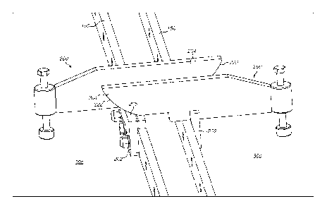
Figure 9 shows the alignment system in place on the tower segments.
DETAILED DESCRIPTION
Figure 1 shows a partial span 10 of an assembled wind turbine tower, the tower
being constructed from several shells 11 being welded or bolted together. For
clarity only,
the lower five shells 11 are labelled in Figure 1, but it will be appreciated
that the shell
structure continues along the length of the tower span 10.
Span 10 is shown as comprising two cylindrical sections 14a and 14b joined
together
to one another at horizontal join 12. Horizontal flanges 17 are located at the
horizontal joins
12, and at the top and bottom of the span 10, in order to allow adjacent
sections to be
connected together. A tower will often be made up of many cylindrical
sections, depending
on its height. In practice, the opposing horizontal flanges 17 located on the
open ends of the
respective cylindrical sections are brought together using lifting machinery,
such as a tower
17
SUBSTITUTE SHEET (RULE 26)
crane, and the cylindrical sections are then secured to one another using
bolts passing
through bolt holes in the horizontal flanges 17.
As noted above, it is desirable to transport the cylindrical sections as
respective
segments which are then reassembled at the installation site. In the example
shown in
Figure 1, each of the cylindrical sections 14a and 14b are formed by three
segments joined
together at vertical joins 16 running parallel to the axis of rotational
symmetry of the tower.
In alternative embodiments, each cylindrical section may be formed of more or
fewer
segments. Further, the number of segments from which each section is formed
may differ
depending on where in the tower the section will be located. As the diameter
of the tower is
largest at the bottom, the cylindrical sections for this part of the tower may
be divided into
more segments than sections from the top of the tower where the diameter is
smaller.
The segments are joined to one another by bolting along the complementary
vertical
flanges arranged on their interior surfaces. The vertical flanges cannot be
seen in Figure 1
but are visible in Figure 9. Joining the segments together into the
cylindrical sections is
preferably carried out before the step of assembling the cylindrical sections
into the tower.
The segments may be arranged horizontally while they are joined to one
another.
As mentioned above, securing the segments together using vertical flanges to
make
sections, and securing the sections together using horizontal flanges in order
to construct
the tower, is known from published patent application number WO 2004/083633
Al, filed on
19 March 2003.
The segments may have substantially the same arc length and therefore subtend
substantially the same angle with respect to the centre of the tower section.
Alternatively, it
may be preferable to cut the tower section into segments of unequal arc
lengths.
The wind turbine towers described and illustrated herein are cylindrical in
shape.
They may also be tapered so that the diameter of the tower at the base is
greater than the
diameter of tower near the nacelle. Although a cylinder with a circular cross-
section has
been described, the cross-section may also be elliptical, polygonal, or
generally polygonal,
that is polygonal but with curved or rounded edges. For polygonal cross-
sections, the
segments of the vertical wind turbine sections can be formed so that once
assembled the
vertical edges of the segments are positioned mid-way or partially mid-way
along the sides
of the surface, rather than at the vertices of the cylinder. This will mean
that the segments
will have a curved, angled or bent surface profile between the two vertical
edges.
18
CA 2945861 2018-01-25
CA 02945861 2016-10-14
WO 2015/161855 PCT/DK2015/050096
The reassembly of the tower segments to form cylindrical tower sections will
now be
described.
As shown in Figure 2A, the tower segments are delivered to the site of the
wind
turbine construction on suitable transport means such as a trailer. Each tower
segment is
removed from the trailer and lowered onto a suitable support structure such as
the roller bed
20 using a crane 34. Other suitable support structures for supporting the
tower segments
are available. Figures 2A and 213 show the unloading of a first tower segment
30c. A
mounting bracket 40 is attached, for example by means of hooks and loops, to
the crane 34.
It is also bolted onto, or grips onto, the segment 30c. Mounting bracket 40 is
equipped with
rotation means 42 which rotates about its longitudinal axis, allowing the
angle of the
segment 30c to which the mounting bracket is attached to be changed relative
to the crane
34. Rotation means 42 comprises, for example, an electric motor and gear
system in order
to rotate segment 30b in a controlled way at the same time as it is lowered by
the crane 34.
Figure 3A shows how reassembly of the tower section continues with the next
segment, 30b, as shown being lifted by the crane 34 in the figure. The segment
30b arrives
at the construction site in a similar manner to that of segment 30c and is
lowered into contact
with segment 30c. Figure 3B shows the segment 30b being lowered to come into
contact
with segment 30c. The vertical flanges along the edges of the respective
segments are then
joined. The rotation means 42 then causes segment 30b to rotate in the
direction shown by
the arrow 130, clockwise in this case, so that both segments 30b and 30c
rotate. The final
segment 30a can then be lifted and lowered into position, filling the gap
between the two
segments as illustrated in Figure 4.
Figure 5 shows the reassembled tower section, with all of the segments 30a,b,c
in
place and the joins between adjacent segments, which are present along the
lines 16 in the
tower section, secured. This is made possible by longitudinal flanges 150
running the length
of the lines 16, which are secured to each other with a row of bolts 152 and
nuts 154 passing
through regularly spaced holes in the flanges 150. .
During the connection of the adjacent segments, the tower segments 30a,b,c are
rotatably adjusted until the adjacent vertical flanges 150 are aligned with
each other and at
the desired separation. The vertical flanges 150 are then bolted together
along their length
using conventional bolting methods. The vertical flanges 150 may be retained
in a horizontal
position during the connection process.
During the process of connecting the vertical flanges 150 of the adjacent
tower
segments, an alignment system according to the invention (not shown in the
previously
19
SUBSTITUTE SHEET (RULE 26)
CA 02945861 2016-10-14
WO 2015/161855 PCT/0K2015/050096
described figures) is used to facilitate the alignment of the vertical flanges
150 of the
adjacent tower segments 30a,b,c. The alignment system comprises a plurality of
alignment
tools 200 mounted along each of the vertical flanges 150 to be connected. The
alignment
tools 200 are mounted on each flange 150 such that each alignment tool 200
will be
positioned opposite a corresponding alignment tool on the opposite vertical
flange once the
tower segments are brought together. As described above, the alignment tools
200 operate
in pairs which engage with each other during the alignment process to align
the pair of
vertical flanges. For each tower segment, a plurality of alignment tools 200
may be spaced
apart along the length of the vertical flange 150. It should be noted that the
description of
ways to handle the sections with reference to figs. 1-5 should not in any way
be limiting with
respect to the alignment tool, use of it and methods related hereto. A skilled
person in the art
would appreciate other handling steps to bring two vertical flanges towards
each other
whereby alignment tools as described herein would find use.
One of the alignment tools 200 of the alignment system is shown in Figures 6
to 8.
The other alignment tools of the alignment system are of a corresponding
construction. The
alignment tool 200 comprises an attachment plate 202 and an alignment head 204
mounted
on the top edge 206 of the attachment plate 202.
As shown in Figure 8, the attachment plate 202 is a substantially rectangular
plate
having a straight top edge 206, a central bolt hole 208 and a pair of slotted
holes 210 on
either side of the central bolt hole 208. As illustrated in Figures 8 and 9,
the attachment
plate 202 is connected to a vertical flange by means of a central bolt
fastener 212 passing
through the central bolt hole 208 and a pair of support pin fasteners 214
passing through the
slotted holes 210. Each of the fasteners 212, 214 passes through the
respective hole in the
attachment plate 202 and into a hole in the vertical flange 150. In this way,
the attachment
plate 202 is connected to the vertical flange to mount the alignment tool in
the inside of the
tower segment. Once mounted on the vertical flange, the top edge 206 of the
attachment
plate 202 lies a small distance above the top edge of the vertical flange 150
and provides
the top guiding edge of the alignment tool.
An additional flange 216 is provided at the top of the attachment plate 202,
with the
top edge of the additional flange 216 substantially flush with the top edge
206 of the
attachment plate 202. The lower edge of the additional flange 216 lies in
contact with the
top edge of the vertical flange 150.
The alignment head 204 comprises a single integral plate mounted at the top
edge of
the attachment plate 202, proximate one end of the attachment plate 202. The
alignment
head 204 is seated over the top edge 206 of the attachment plate 202 and the
top edge of
SUBSTITUTE SHEET (RULE 26)
CA 02945861 2016-10-14
WO 2015/161855 PCT/0K2015/050096
the additional flange 216 and is welded in place such that the alignment head
204 and the
attachment plate 202 are fixed relative to each other.
The alignment head 204 comprises a front portion 218 extending in a forwards
direction from the attachment plate 202 and a rear portion 220 extending in a
backwards
direction from the attachment plate 202. The front portion 218 and the rear
portion 220 are
integrally formed in a substantially straight line and form a continuous
longitudinal piece
which has a longitudinal axis that is substantially perpendicular to the
longitudinal axis of the
attachment plate 202. Once the alignment tool 200 is mounted on the vertical
flange 150 of
the tower segment, the front portion 218 extends towards and over the
longitudinal edge
whilst the rear portion 220 extends backwards into the main body of the tower
segment.
The front portion 218 of the alignment head 204 has a lower guiding surface
222
which is adapted to slide over the top guiding edge 206 of the attachment
plate 202 of the
opposite alignment tool as the tower segments are brought together. The lower
guiding
surface 222 comprises a first convexly curved portion 222a which extends
substantially from
the top edge of the alignment head 204 at the distal end of the front portion
218 to a position
approximately halfway along the front portion. The distal end of the front
portion is therefore
curved. The lower guiding surface 222 further comprises a flat, horizontal
portion 222b
extending continuously from the curved portion 222 towards the attachment
plate 202. At a
distance from the attachment plate 202, between the attachment plate 202 and
the distal
end of the front portion 218, an abutment 224 is provided in the lower guiding
surface 222,
which provides a substantially vertical abutment surface.
The rear portion 220 of the alignment head 204 comprises an annulus 226 at the
distal end, furthest from the attachment plate 202, which provides a vertical
channel to
receive an adjustable screw member 228 which is used to engage the alignment
tool 200
with the inner surface of the tower segment, as described above. The screw
member 228 is
provided with a resilient cap 230 for contact with the surface of the tower
segment. During
the process of mounting the alignment tool 200 on the vertical flange 150, the
screw member
228 may be adjusted to bring the distal end into contact with the inner
surface of the tower
segment.
Figure 9 shows a pair of tower segments 30b,c being reconnected, with the
alignment system in place on the vertical flanges 150 of the segments. On each
tower
segment, a plurality of alignment tools 200 has been connected to the vertical
flange 150 at
spaced apart intervals along the flange and the tools have each been secured
and braced
against the inner surface of the tower segment by means of the respective
screw members
228. The alignment tools 200 are mounted at corresponding positions on each of
the pair of
21
SUBSTITUTE SHEET (RULE 26)
CA 02945861 2016-10-14
WO 2015/161855
PCT/0K2015/050096
flanges so that when the adjacent tower segments 30b,c are brought together on
the roller
bed, the alignment tools 200 are brought together into co-operating pairs. One
such pair is
illustrated in Figure 9.
For each pair of alignment tools 200, the alignment head 204 of each tool is
brought
into contact with the top guiding edge 206 of the attachment plate 202 of the
opposite
alignment tool 200, at the opposite end of the attachment plate 202 to the end
at which the
corresponding alignment head is mounted 204. As the tower segments 30b,c are
rotated to
bring the longitudinal edges towards each other, the alignment heads 204 will
each slide
over the opposite attachment plate 202 and the lower guiding surface 222 will
guide the
vertical flanges and align them at the same level as each other so that the
holes in the
flanges are lined up with each other. The alignment system retains the
vertical flanges in
alignment with each other whilst the bolts are passed through the holes in the
vertical
flanges to connect the flanges together. The alignment tools 200 may then be
removed from
the tower segments.
The example described above utilises an alignment system according to the
invention comprising a pair of alignment tools. It will be appreciated that
the described
alignment method could be carried out using an alignment system according to
the invention
using a guiding bracket in place of the second alignment tool.
22
SUBSTITUTE SHEET (RULE 26)