Note : Les descriptions sont présentées dans la langue officielle dans laquelle elles ont été soumises.
CA 02947171 2016-10-26
WO 2015/171806 PCT/US2015/029525
INTEGRATED REPEATER
CROSS-REFERENCE TO RELATED APPLICATIONS
[001] This application claims priority to and the benefit of U.S.
Provisional Application
No. 61/989,379, filed May 6, 2014, which is incorporated herein by reference
in its entirety.
TECHNICAL FIELD
[002] The subject matter described herein relates to wireless networks, and
more
particularly to an improved integrated repeater that maximizes the isolation
between a donor
antenna and a server antenna by placing the server antenna in a physical
location where the
donor antenna has a transmission null and/or vice-versa.
BACKGROUND
[003] The gain of a repeater is to a large extent determined by the amount
of isolation
that can be achieved between the donor and server antennas of the repeater
(see diagram 100 of
FIG. 1). The higher the isolation, the higher the potential gain of the
repeater.
[004] When the donor and server antennas are in the same physical
enclosure, or at least
in close proximity to each other, maximizing the isolation level becomes
increasingly difficult.
Typically, repeaters with integrated donor and server antennas utilize highly
directive antennas
on either the donor or the server side, or more commonly on both the donor and
the server side to
achieve high isolation. An example of a commonly used architecture is to use
directive patch
antennas on a large ground plane to provide high isolation levels. When the
operating frequency
1
CA 02947171 2016-10-26
WO 2015/171806 PCT/US2015/029525
of the repeater is high (around 2GHz and higher), this is a reasonably good
strategy as the
wavelength of the signals is relatively short. However, at lower frequencies,
such as the 3GPP
bands 5 and 12 (700-900 MHz), the wavelength of the repeated signal is long
(300 ¨ 400mm)
which means that the physical size of a patch antenna and ground plane needs
to be large to
achieve high isolation.
SUMMARY
[005] In one aspect, an integrated repeater is disclosed that maximizes the
isolation
between a donor antenna and the server antenna by placing the server antenna
in a physical
location where the donor antenna has a transmission null and/or vice-versa.
[006] The integrated repeater may comprise a repeater housing. The
integrated repeater
may comprise a donor antenna. The donor antenna may be disposed within the
repeater housing.
The donor antenna may be configured to transmit and/or receive a wireless
signal from a base
station. The donor antenna may be configured to emit a transmission field
having one or more
null-field points.
[007] The integrated repeater may comprise a server antenna. The server
antenna may
be disposed within the repeater housing. The server antenna may be physically
separated from
the donor antenna. The server antenna may be configured to transmit and/or
receive a wireless
signal from one or more wireless devices. The server antenna may be disposed
proximate to a
location of at least one of the one or more null-field points of the
transmission field from the
donor antenna. The serer antenna may be disposed as such for signal isolation
between the
server antenna and the donor antenna.
2
CA 02947171 2016-10-26
WO 2015/171806 PCT/US2015/029525
[008] In some implementations, a plurality of donor antennas may be
disposed within
the repeater housing. The donor antennas may emit one or more transmission
fields that have a
plurality of null-field points within the repeater housing. A plurality of
server antennas may be
disposed within the repeater housing. Individual ones of the plurality of
server antennas may be
disposed proximate to individual ones of the plurality of null-field points
within the repeater
housing.
[009] The one or more donor antennas and/or the one or more server antennas
may be
dipole antennas, multiband antennas and/or other forms of antennas.
[0010] In some variation, at least one of the one or more null-field
points of the signals
emitted from the donor antenna and/or the server antenna may be aligned with
the repeater
housing.
[0011] In some variations, the signals transmitted by the donor antenna
and/or the server
antenna are orthogonally polarized. The orthogonally polarized signals
transmitted by the donor
antenna may be orthogonal to the orthogonally polarized signals transmitted by
the server
antenna.
[0012] In another aspect, a method of configuring an integrated repeater
is described.
The method may include providing a donor antenna. The donor antenna configured
to transmit
and/or receive a wireless signal from a base station. The donor antenna may
emit a signal having
one or more null-field points.
[0013] The method may include providing a server antenna. The server
antenna may be
configured to transmit and/or receive a wireless signal from one or more
wireless devices. The
server antenna may emit a signal having one or more null-field points.
3
CA 02947171 2016-10-26
WO 2015/171806 PCT/US2015/029525
[0014] The position of at least one of the one or more null-field points
of the signal
emitted from the donor antenna may be determined. The positon of at least one
of the one or
more null-field points of the signal emitted from the server antenna may be
determined.
[0015] The donor antenna may be positioned proximate to at least one of
the one or more
null-field points of the signal emitted from the server antenna. The server
antenna may be
positioned proximate to at least one of the one or more null-field points of
the signal emitted
from the donor antenna.
[0016] The method may include determining the dimensions of a repeater
housing. The
dimensions of the repeater housing may be based on a requirement that at least
one of the
positions of the one or more null-field points of the signal emitted by the
donor antenna and at
least one of the positions of the one or more null-field points of the signal
emitted by the server
antenna are within the repeater housing when the donor antenna and the server
antenna are
disposed in the repeater housing. The dimensions of the repeater housing may
be based on
having at least one of the one or more null-field points of the signals
emitted from the donor
antenna and/or the server antenna being aligned with the repeater housing.
[0017] Implementations of the current subject matter can include, but are
not limited to,
systems and methods consistent including one or more features are described as
well as articles
that comprise a tangibly embodied machine-readable medium operable to cause
one or more
machines (e.g., computers, mobile communication devices, etc.) to result in
operations described
herein. Similarly, computer systems are also described that may include one or
more processors
and one or more memories coupled to the one or more processors. A memory,
which can
include a computer-readable storage medium, may include, encode, store, or the
like one or more
4
CA 02947171 2016-10-26
WO 2015/171806 PCT/US2015/029525
programs that cause one or more processors to perform one or more of the
operations described
herein. Computer implemented methods consistent with one or more
implementations of the
current subject matter can be implemented by one or more data processors
residing in a single
computing system or multiple computing systems. Such multiple computing
systems can be
connected and can exchange data and/or commands or other instructions or the
like via one or
more connections, including but not limited to a connection over a network
(e.g. the Internet, a
wireless wide area network, a local area network, a wide area network, a wired
network, or the
like), via a direct connection between one or more of the multiple computing
systems, etc.
[0018] The details of one or more variations of the subject matter
described herein are set
forth in the accompanying drawings and the description below. Other features
and advantages of
the subject matter described herein will be apparent from the description and
drawings, and from
the claim. While certain features of the currently disclosed subject matter
are described for
illustrative purposes in relation to an enterprise resource software system or
other business
software solution or architecture, it should be readily understood that such
features are not
intended to be limiting. The claim that follows this disclosure is intended to
define the scope of
the protected subject matter.
DESCRIPTION OF DRAWINGS
[0019] The accompanying drawings, which are incorporated in and
constitute a part of
this specification, show certain aspects of the subject matter disclosed
herein and, together with
the description, help explain some of the principles associated with the
disclosed
implementations. In the drawings,
CA 02947171 2016-10-26
WO 2015/171806 PCT/US2015/029525
[0020] FIG. 1 is a diagram illustrating a repeater having a donor antenna
and a server
antenna;
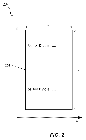
[0021] FIG. 2 is a diagram illustrating isolation between a donor antenna
and a server
antenna;
[0022] FIG. 3 is a diagram illustrating isolation among two donor
antennas and two
server antennas; and
[0023] FIG. 4 is a diagram illustrating a radiation pattern for one
donor/server pair of
antennas within a repeater housing.
[0024] FIG. 5 illustrates a method of configuring an integrated repeater
in accordance
with one or more aspects of the presently disclosed subject matter.
DETAILED DESCRIPTION
[0025] The current subject matter provides a departure from the
traditional design
approach and form factor for a repeater with integrated donor and server
antenna. The basic
principle is to maximize the isolation between the donor antenna and the
server antenna by
placing the server antenna in a physical location where the donor antenna has
a transmission null
and/or vice-versa. One example of such an antenna arrangement is illustrated
in diagram 200 of
FIG. 2. In this arrangement, the donor and server antennas are both dipole
antennas. Dipole
antennas have nulls in the radiation pattern in the y direction as shown in
FIG. 2. Therefore, in
an ideal world, the isolation between the donor and server antennas shown
below is infinite. Of
course, under practical conditions the isolation would not be infinite.
6
CA 02947171 2016-10-26
WO 2015/171806 PCT/US2015/029525
[0026] This current subject matter can also be applied to cover multi-
band scenarios as
well where the donor and server antennas are multiband antennas or, to the
case where multiple
donor and server antennas are used. An example of a physical antenna
arrangement for a quad-
band repeater is illustrated in diagram 300 of FIG. 3.
[0027] The radiation pattern for one donor/server pair of antennas within
the repeater
housing is illustrated in diagram 400 of FIG. 4. As can be seen, the nulls in
the pattern in the z-
direction are clearly visible. These nulls are aligned within the repeater
housing leading to an
increase in the isolation between the donor and server antennas.
[0028] In the examples shown, dipole antennas were used to illustrate the
concept.
However, any type of antenna may be used as a donor or server. The type of
antenna used will
define the location of the radiation nulls and hence the relative positioning
of the antennas within
the housing. For the dipole case shown, the resultant repeater will have a
long tubular shape for
example.
[0029] A second issue to consider when optimizing the isolation between
the donor and
the server is the polarization of the antennas. In addition to placing the
antennas in the position
of a relative null, the antennas can be designed with orthogonal polarization.
This will increase
the isolation and also make the design more robust against reduction in
isolation due to scattering
from nearby objects such as walls. For example, the donor antennas could be
vertically
polarized and the server antenna could be horizontally polarized.
[0030] FIG. 5 illustrates a method 500 for of configuring an integrated
repeater in
accordance with one or more aspects of the presently disclosed subject matter.
The operations
described herein with respect to method 500 may be performed by one or more of
the elements
7
CA 02947171 2016-10-26
WO 2015/171806 PCT/US2015/029525
described herein. Certain ones of the operations of method 500 may be
performed by human
action, computer hardware, computer software, computer firmware and/or by
other methods.
The operations illustrated in FIG. 5 are illustrative only. In some
variations, one or more
operations may be omitted from the method 500. In some variations, one or more
additional
and/or alternative operations may be included in method 500.
[0031] At 501, a donor antenna may be provided. The donor antenna may be
configured
to transmit and/or receive a wireless signal from a base station. The donor
antenna may emit a
signal having one or more null-field points. In some implementations a
plurality of donor
antennas may be provided. The one or more donor antennas may be dipole
antennas, multiband
antennas, or other form of antenna.
[0032] At 502, a server antenna may be provided. The server antenna may
be configured
to transmit and/or receive a wireless signal from one or more wireless
devices. The server
antenna may emit a signal having one or more null-field points. In some
implementations, a
plurality of server antennas may be provided. The one or more server antennas
may be dipole
antennas, multiband antennas, or other form of antenna.
[0033] At 503, the position of at least one of the one or more null-field
points of the
signal emitted from the donor antenna may be determined.
[0034] At 504, the positon of at least one of the one or more null-field
points of the signal
emitted from the server antenna may be determined.
[0035] At 505, the dimensions of a repeater housing may be determined.
The dimensions
of the repeater housing may be based on a requirement that at least one of the
positions of the
one or more null-field points of the signal emitted by the donor antenna and
at least one of the
8
CA 02947171 2016-10-26
WO 2015/171806 PCT/US2015/029525
positions of the one or more null-field points of the signal emitted by the
server antenna are
within the repeater housing when the donor antenna and the server antenna are
disposed in the
repeater housing. In some implementations, the dimensions of the repeater
housing may be
determined based on having at least one of the one or more null-field points
of the signals
emitted from the donor antenna and/or the server antenna being aligned with
the repeater
housing. With reference to FIG. 2, the positions of at least one of the one or
more null-field
points of the donor antenna and/or the server antenna may be used to determine
the dimensions
of the repeater housing 201. FIG. 2 shows two dimensions, p and q, of the
repeater housing 201.
The positions of the one or more null-field points may be used to determine
the third dimension
of the repeater housing. In some implementation, the positions of the one or
more null-field
points associated with the donor antenna and/or associated with the server
antenna may be
utilized to determine a shape for the repeater housing. The repeater housing
is shown in FIG. 2
as having a regular polygonal shape, however, this disclosure anticipates any
shape of housing
for the repeater, including irregular shapes.
[0036] At 506, the donor antenna may be positioned proximate to at least
one of the one
or more null-field points of the signal emitted from the server antenna.
[0037] At 507, the server antenna may be positioned proximate to at least
one of the one
or more null-field points of the signal emitted from the donor antenna.
[0038] At 508, the signals transmitted by the donor antenna and/or the
server antenna
may be orthogonally polarized. A plane a plane for the orthogonally polarized
signals emitted by
the server antenna may be selected. The plane selected may be one such that
the plane of the
9
CA 02947171 2016-10-26
WO 2015/171806 PCT/US2015/029525
orthogonally polarized signals emitted by the server antenna is orthogonal to
the plane for the
orthogonally polarized signals emitted by the donor antenna.
[0039] One or more aspects or features of the subject matter described
herein can be
realized in digital electronic circuitry, integrated circuitry, specially
designed application specific
integrated circuits (ASICs), field programmable gate arrays (FPGAs) computer
hardware,
firmware, software, and/or combinations thereof. These various aspects or
features can include
implementation in one or more computer programs that are executable and/or
interpretable on a
programmable system including at least one programmable processor, which can
be special or
general purpose, coupled to receive data and instructions from, and to
transmit data and
instructions to, a storage system, at least one input device, and at least one
output device. The
programmable system or computing system may include clients and servers. A
client and server
are generally remote from each other and typically interact through a
communication
network. The relationship of client and server arises by virtue of computer
programs running on
the respective computers and having a client-server relationship to each
other.
[0040] These computer programs, which can also be referred to as
programs, software,
software applications, applications, components, or code, include machine
instructions for a
programmable processor, and can be implemented in a high-level procedural
and/or object-
oriented programming language, and/or in assembly/machine language. As used
herein, the term
"machine-readable medium" refers to any computer program product, apparatus
and/or device,
such as for example magnetic discs, optical disks, memory, and Programmable
Logic Devices
(PLDs), used to provide machine instructions and/or data to a programmable
processor,
CA 02947171 2016-10-26
WO 2015/171806 PCT/US2015/029525
including a machine-readable medium that receives machine instructions as a
machine-readable
signal. The term "machine-readable signal" refers to any signal used to
provide machine
instructions and/or data to a programmable processor. The machine-readable
medium can store
such machine instructions non-transitorily, such as for example as would a non-
transient solid-
state memory or a magnetic hard drive or any equivalent storage medium. The
machine-readable
medium can alternatively or additionally store such machine instructions in a
transient manner,
such as for example as would a processor cache or other random access memory
associated with
one or more physical processor cores.
[0041] The subject matter described herein can be embodied in systems,
apparatus,
methods, and/or articles depending on the desired configuration. The
implementations set forth
in the foregoing description do not represent all implementations consistent
with the subject
matter described herein. Instead, they are merely some examples consistent
with aspects related
to the described subject matter. Although a few variations have been described
in detail above,
other modifications or additions are possible. In particular, further features
and/or variations can
be provided in addition to those set forth herein. For example, the
implementations described
above can be directed to various combinations and subcombinations of the
disclosed features
and/or combinations and subcombinations of several further features disclosed
above. In
addition, the logic flows depicted in the accompanying figures and/or
described herein do not
necessarily require the particular order shown, or sequential order, to
achieve desirable results.
Other implementations may be within the scope of the following claims.
11