Note : Les descriptions sont présentées dans la langue officielle dans laquelle elles ont été soumises.
CA 02947244 2016-10-27
WO 2015/167572 PCT/US2014/036416
Attorney Docket No. 85978-0002
ELECTRONIC CONTACTLESS HORN
AND SOUND DEVICE
BACKGROUND
[1] Apparatuses consistent with the exemplary embodiments relate to a
contactless
sound device, such as a horn, that may be configured to output different
and/or multiple pitches
using a replaceable, or interchangeable, electronic integrated circuit ("IC")
module. In
particular, the exemplary embodiments relate to a more energy-efficient and
longer-lasting sound
device that utilizes a contactless horn or sound device in connection with a
replaceable, or
interchangeable, electronic IC module to generate sound.
[2] Apparatuses of the related art include a metal contact, typically but
not always
made out of tungsten, which is magnetically manipulated by an electromagnet in
order to cause
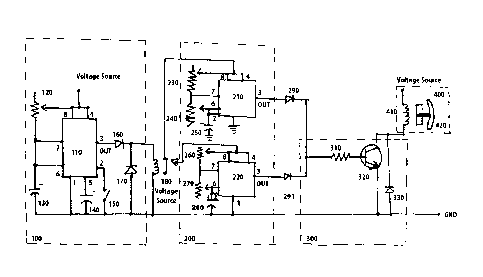
the diaphragm of a horn to move, thus generating sound in a single pitch. By
varying the
distance between the contact and the diaphragm, one may manipulate the horn to
output different
pitches. However, in order to vary the distance between the contact and the
diaphragm, and thus
achieve these different pitches, the horn's physical structure must be
changed, which is a time-
consuming, labor-intensive, and costly exercise.
[3] Furthermore, in the related art, the contact used by the sound device
requires a
relatively large amount of energy to move the diaphragm due to the extra
weight of the metal
contacts required by the related art horn designs. The use of metal contacts
in a horn or sound
device may also cause sparking around the contact, which increases the risk of
fire when the
horn is used in certain environments, thus making these related art
apparatuses unsuitable for use
in highly flammable environments such as mining operations. The fire risk
inherent in related art
horn and sound devices also limits the types of materials that can be used in
the construction of
1
CA 02947244 2016-10-27
WO 2015/167572 PCT/US2014/036416
Attorney Docket No. 85978-0002
the horn to materials that are nonflammable, thus precluding the use of some
lightweight and/or
less expensive alternative materials in the horn design.
[4] The metal contacts used in related art horn devices also frequently
wear out or
corrode, thereby forcing the user to replace the contact or, in most cases,
the entire horn.
[5] In certain applications, such as in vehicle horns, there is a need for
a horn that can
produce multiple pitches. Currently, vehicle manufacturers use multiple horns
(typically one low
note horn and one high note horn) to overcome this limitation. However, the
use of multiple
horns increases the weight of the vehicle, which negatively impacts the fuel
efficiency of the
vehicle and increases the energy usage of the vehicle. Indeed, extant vehicle
horns consume a
large amount of energy, making them undesirable for use in electric and hybrid
vehicles.
SUMMARY
[6] According to an aspect of one or more exemplary embodiments, there is
provided
a contactless horn and sound device including a replaceable, or
interchangeable, electronic IC
module, which provides greater energy-efficiency over related art horn and
sound devices by
eliminating the metal contacts required by prior art designs.
[7] According to another aspect of one or more exemplary embodiments, there
is
provided a contactless horn and sound device with a replaceable, or
interchangeable, electronic
IC module, with a longer expected lifespan than prior art horn and sound
devices through the
elimination of the metal contacts required by prior art designs.
[8] According to another aspect of one or more exemplary embodiments, there
is
provided a replaceable, or interchangeable, IC module that allows a single
contactless horn and
sound device to generate multiple frequency tones.
2
CA 02947244 2016-10-27
WO 2015/167572 PCT/US2014/036416
Attorney Docket No. 85978-0002
[9] According to another aspect of one or more exemplary embodiments, there
is
provided a replaceable, or interchangeable, IC module that allows for faster
and easier
modification of the tones produced by the contactless horn and sound device.
[10] According to another aspect of one or more exemplary embodiments,
there is
provided a contactless horn and sound device that may be used in highly
flammable
environments.
[11] According to another aspect of one or more exemplary embodiments,
there is
provided a contactless horn and sound device that may be constructed out of
lighter weight
materials.
[12] According to another aspect of one or more exemplary embodiments,
there is
provided a contactless horn and sound device that may be constructed out of
less expensive
materials.
[13] According to another aspect of one or more exemplary embodiments,
there is
provided a contactless horn and sound device that is more energy efficient and
more suitable for
use in hybrid and electric vehicles.
[14] According to an aspect of one or more exemplary embodiments, there is
provided
a contactless horn that may be configured to output different and/or multiple
pitches at different
intervals using a replaceable, or interchangeable, electronic IC module. The
electronic IC
module may include one or more sequencers electrically connected via one or
more relays to at
least one signal generator which is electrically connected to an output
driver. If present, the one
or more sequencers may be used to select the at least one signal generator.
Each signal generator
is configured to generate at least one frequency signal, and optionally
multiple frequency signals.
The output of the signal generator is electrically connected to an output
driver, which amplifies
3
CA 02947244 2016-10-27
WO 2015/167572 PCT/US2014/036416
Attorney Docket No. 85978-0002
the signal received from the signal generator. The electronic IC module may be
physically
attached to an IC connection interface located on the exterior of the
contactless horn body. The
IC connection interface electrically connects the electronic IC module to an
electromagnet that
drives the diaphragm of the contactless horn to create the selected
preconfigured frequency
sound(s).
BRIEF DESCRIPTION OF THE DRAWINGS
[15] Fig. 1 is a circuit diagram illustrating an electronic circuit for a
contactless horn
and sound device according to an exemplary embodiment.
[16] Fig. 2 is a diagram illustrating a contactless horn and sound device
with attached
electronic integrated circuit module according to an exemplary embodiment.
[17] Fig. 3 is a diagram illustrating the side and bottom view of the
diaphragm portion
of a contactless horn and sound device according to an exemplary embodiment.
[18] Fig. 4 is a diagram illustrating a contactless horn and sound device
that interacts
with a vehicle system according to an exemplary embodiment that generates
multiple tones
based on input received from the vehicle system.
[19] Fig. 5 is a diagram illustrating a contactless horn and sound device
according to
an exemplary embodiment that may communicate with surrounding vehicles.
[20] Fig. 6 is a circuit diagram illustrating an electronic circuit for a
contactless horn
and sound device according to an exemplary embodiment.
DETAILED DESCRIPTION OF EXEMPLARY EMBODIMENTS
[21] Reference will now be made in detail to the following exemplary
embodiments,
which are illustrated in the accompanying drawings, wherein like reference
numerals refer to the
like elements throughout. The exemplary embodiments may be embodied in various
forms
4
CA 02947244 2016-10-27
WO 2015/167572 PCT/US2014/036416
Attorney Docket No. 85978-0002
without being limited to the exemplary embodiments set forth herein.
Descriptions of well-
known parts are omitted for clarity.
[22] Fig. 1 is a circuit diagram of an electronic circuit for a contactless
horn and sound
device according to an exemplary embodiment. Referring to Fig. 1, a
contactless horn and sound
device according to an exemplary embodiment may include a sequencer 100, a
relay 180, a
signal generator 200, an output driver 300, and a contactless horn and housing
400.
[23] The sequencer 100 is responsible for selecting the frequency of the
sound to be
output by the signal generator 200 through the use of the relay 180, as well
as the interval of the
sound signal. The sequencer 100 may include a timer IC chip 110, such as the
LM555 Timer IC
chip of Texas Instruments, configured to output a signal waveform that drives
a relay between
two states. Alternatively, the sequencer can use a transistor or other
suitable circuitry or
electronics instead of an LM555 Timer IC chip.
[24] The control voltage pin (8) and reset pin (4) of the timer IC chip 110
may be
connected to a voltage source that may range from 5V to 15V DC. An adjustable
resistor 120
may be wired to the voltage source and to control voltage pin (8), reset pin
(4), threshold pin (6),
and discharge pin (7) of the timer IC chip 110, and may also be wired to
electrolytic capacitor
130. A switch 150 may be connected to the trigger pin (2) of the timer IC chip
110. The output
pin (3) of the timer IC chip 110 may be connected to a forward-biased diode
160. The diode 160
may be connected to a reverse-biased diode 170 and may also be connected to a
relay 180.
Electrolytic capacitors 130 and 140, ground pin (1) of the timer IC chip 110,
switch 150, and
diode 170 may then be wired to ground.
[25] The output signal of the timer IC 110 may be used to select the
position of the
relay 180, thereby selecting the frequency generated by the signal generator
200. Signal
generator 200 may include two timer IC chips 210 and 220, each of which may be
configured to
produce a set frequency signal by adjusting the resistance values of the
adjustable resistors 230,
240, 260, and 270, as well as adjusting the capacitance values of electrolytic
capacitors 250 and
280. Some exemplary frequencies that may be produced include 250 Hz, 300 Hz,
and 435 Hz,
however, the timer IC chips may be configured to produce any frequency that
may be desirable
in a particular application. Timer IC chips 210 and 220 may be the LM555 timer
IC chip
discussed above or any other suitable timer IC chip.
[26] The output of the relay 180 may be connected to the control voltage
pin (8) and
reset pin (4) of the timer IC chips 210 and 220, and also may be connected to
the adjustable
resistors 230 and 260, respectively. The adjustable resistors 230 and 260 may
be connected to
the discharge pin (7) of the timer IC chips 210 and 220, respectively, and may
also be connected
to adjustable resistors 240 and 270, respectively. Adjustable resistors 240
and 270 may be
connected to threshold pin (6) and trigger pin (2) of the timer IC chips 210
and 220, respectively,
and may also be connected to electrolytic capacitors 250 and 280 respectively.
Ground pin (1) of
the timer IC chips 210 and 220 and electrolytic capacitors 250 and 280 may be
wired to ground.
Output pin (3) of the timer IC chips 210 and 220 may be connected to forward-
biased diodes 290
and 291, respectively, and may output a signal of a preconfigured frequency
and interval to those
diodes.
[27] The diodes 290 and 291 may be connected to the output driver 300. The
output
driver 300 may be used to amplify the signal outputted by the circuitry of
signal generator 200.
Output driver 300 may comprise a resistor 310 which may be connected to the
base of the NPN
transistor 320. The emitter of the NPN transistor may be connected to ground
and the diode 330
may also be connected to ground. The collector of the NPN transistor 320 may
be connected to
6
Date recu/Date Received 2020-07-09
CA 02947244 2016-10-27
WO 2015/167572 PCT/US2014/036416
Attorney Docket No. 85978-0002
the reverse-biased diode 330 and may also be connected to the contactless horn
and housing 400,
or other circuits to provide the desired signal output.
[28] Fig. 2 is a diagram illustrating a contactless horn and sound device
with attached
electronic integrated circuit module according to an exemplary embodiment.
Referring now to
Fig. 2, the contactless horn and housing 400 may comprise an electromagnet 410
which may
magnetically manipulate (i.e., repel and attract) the metal plate 490 secured
to the bottom
diaphragm 430 of the contactless horn to create a tone in accordance with the
selected frequency
generated by the signal generator 200. The electromagnet 410 may be comprised
of a coil,
preferably a copper coil that is 20 gauge or higher (i.e., smaller in
diameter), wrapped around a
metal (e.g., steel, iron, or other magnetizable metal) bolt. However, the
gauge of the copper coil
may be higher or lower depending on a variety of factors, such as power,
weight, etc. The output
of the output driver 300 is electrically connected to the electromagnet 410
via the IC connection
interface 450, which is preferably positioned on the exterior of the base 440.
The base 440 may
be constructed using a lightweight plastic, a lightweight metal, or another
suitable material. Top
diaphragm 420 and bottom diaphragm 430 may be secured together using bolt 460
and washers
470 and 480 and the bottom diaphragm 430 may then be secured to the base 440
along the rim of
the base 440, thereby allowing the free movement of the center portion of the
diaphragms 420
and 430 so as to produce the preconfigured frequency sound.
[29] According to an exemplary embodiment, the signal generator 200 may be
used to
generate multiple pitches, tones or notes simultaneously by modifying the
interval at which
different frequencies are generated to create different tones. For example,
the electromagnet 410
may be switched from operating at 300 Hz to 500 Hz every millisecond, so as to
create a low and
7
high tone from a single device. This provides an advantage over related art
horns that use two
separate horns to create two different tones.
[30] Fig. 3 is a diagram illustrating the side view and bottom view of the
diaphragm
portion of a contactless horn and sound device according to an exemplary
embodiment.
Referring now to Fig. 2, there may be a separation between the electromagnet
410 and the metal
plate 490. The separation, or "air gap," preferably comprises a distance
between 0.05 to 0.25
inches, with a tolerance of +/- 0.05 inches. However, this separation or "air
gap" may be
adjusted as needed based on the desired application.
[31] Furthermore, one skilled in the art will recognize that the
contactless horn device
may be modified to play additional frequency tones by adding additional signal
generators 200
and additional sequencers 100 to the electronic IC module and configuring them
according to the
present teachings.
[32] Fig. 4 is a diagram illustrating a contactless horn and sound device
that interacts
with a vehicle system according to an exemplary embodiment that generates
multiple tones
based on input received from the vehicle system. Referring to Fig. 4, sound
device 500 may
interface with a vehicle's motherboard 510 or other similar component that
receives data signals
from various vehicle triggers, switches, and external sensors 520 indicating
the status of the
vehicle, such as, without limitation, the Intelligent Power Distribution
Module (IPDM) found in
Nissan vehicles. Sound device 500 may produce different tones, pitches,
frequencies, sounds
and/or intervals of sounds based on data received from the vehicle motherboard
510. For
example, one or more of the various sensors 520 may send a signal 515
indicating the speed of
the vehicle to the vehicle's motherboard 510, which includes one or more
vehicle central
processing units (CPUs) 511. The vehicle CPU 511 may send a signal 505 to the
sound device
8
Date Recue/Date Received 2020-12-08
500 that is used to control the output of signal generators 200 to output a
particular tone, pitch,
frequency, sound, or sound interval, as discussed above. Data signal 505 or
515 may be received
by receiver 501 of the sound device 500, and provided as input to a CPU 502 to
control
mechanical parts 503 of the sound device 500 to generate a particular sound.
Sound device 500
may also include a transmitter 504 that provides feedback to the vehicle CPU
511 or the various
sensors 520 indicating the status of the sound device and the pitches, tones,
frequencies, or
sounds it has produced.
[331 The contactless horn and sound device of the exemplary embodiment
may modify
the pitch, frequency, or tone produced based on a variety of inputs provided
from the various
sensors 520. For example, the sound device 500 may produce a louder (that is,
higher
amplitude) sound if the vehicle is moving at a high rate of speed than if the
vehicle is moving
slowly or stopped. The sound device 500 may also produce different sounds in
response to a
signal that the vehicle's anti-theft alarm has been triggered, or to announce
that the driver has
locked or unlocked the vehicle. The sound device 500 of the exemplary
embodiment may also
produce multiple alarm sounds depending how the alarm was triggered. For
example, if the
vehicle is accidentally and innocently bumped while the vehicle is not moving,
the sound device
500 may produce a softer tone or more delayed sound interval, as compared to
an alarm that is
triggered by someone or something smashing the vehicle's windshield or window.
The pitches,
frequencies, tones and sounds generated by the sound device 500 may also be
tailored to each
vehicle manufacturer and/ormodel.
[341 Transmitter 504 may also be used to notify the driver of various
conditions
relating to the vehicle. For example, when the vehicle's alarm is triggered,
in addition to
generating a particular sound according to the type of alarm triggered, the
sound device 500 may
9
Date recu/Date Received 2020-07-09
CA 02947244 2016-10-27
WO 2015/167572 PCT/US2014/036416
Attorney Docket No. 85978-0002
cause transmitter 504 to notify the driver that the alarm has been triggered.
For example,
transmitter 504 may notify the driver of the alarm via text message, email, or
other electronic
notification means.
[35] In addition, many vehicles include proximity sensors that detect when
the driver
is within a certain distance of the vehicle, for example, to unlock the doors
of the vehicle as the
driver approaches. Sound device 500 may receive a signal from these proximity
sensors to alert
the driver that the vehicle doors are unlocked when the driver is a certain
distance away from the
vehicle. The tone, pitch, frequency, and volume of the sound may be configured
depending on
the driver's distance from the vehicle.
[36] Sound device 500 may generate various sounds depending on various
other
sensors 520 in accordance with the exemplary embodiment. For example, many
vehicles include
sensors that detect proximity to other vehicles to alert the driver of a
potential impact, (e.g.,
alerting the driver attempting to change lanes of other vehicles in the
driver's blind spot).
According to the exemplary embodiment, such sensors 520 may send signals to
sound device
500 indicating the proximity of an object, and the size or type of object,
based on which the
sound the signal generator 200 will cause the sound device 500 to produce an
appropriate sound.
For example, the sound device 500 of the vehicle in the blind spot may
generate a sound in
response to a signal indicating that the vehicle changing lanes approaches
within a specified
distance of the vehicle. As another example, if a pedestrian is detected, the
sound device 500
may generate a softer sound to warn the pedestrian. If a fast-moving vehicle
is detected, the
sound device 500 may generate a louder sound to warn the driver of the fast
moving vehicle. If
an animal, such as a deer, is detected, the sound device 500 may generate a
sound having a
frequency that will deter the animal and potentially avoid an impact.
CA 02947244 2016-10-27
WO 2015/167572 PCT/US2014/036416
Attorney Docket No. 85978-0002
[37] According to an exemplary embodiment, the sound device 500 may be
connected
to the vehicle CPU 511 or the vehicle's sensors 520 wirelessly. One skilled in
the art would
understand that many wireless technologies (e.g., Bluetooth) may be used to
effect wireless
communication between these devices. Using a wireless connection between these
devices
would eliminate the need for wiring material and switches, reducing cost and
weight and
simplifying manufacturing.
[38] According to an exemplary embodiment, the vehicle sensors 520 or
transmitter
504 may also send a wireless signal that is received by sound devices of
surrounding vehicles
within a certain radius. The sound devices in the surrounding vehicles may
generate sound
having a pitch, frequency, tone, and/or volume that depends on the type of
signal received from
the vehicle sensors 520. For example, sound devices of vehicles closer to the
vehicle whose
sensors 520 transmitted the wireless signal may generate a louder sound than
sound devices in
vehicles that are further away. In addition, the frequency or tone of the
generated sound may
depend on the type of vehicle from which the signal originates. For example,
vehicle sensors
520 located on a truck may cause a deeper and/or louder sound to be produced
in surrounding
vehicles, as compared to vehicles sensors 520 located on a smaller car. The
sound generated by
the sound devices of the surrounding vehicles may be generated within the
surrounding vehicle,
e.g., through the speaker system of the surrounding vehicle, or external of
the surrounding
vehicle, e.g., by the horn of the surrounding vehicle. By generating sound in
the surrounding
vehicles, background interference and noise are less likely to prevent
surrounding drivers from
being alerted to potential dangers.
[39] Fig. 5 is a diagram illustrating a contactless horn and sound device
according to
an exemplary embodiment that may communicate with surrounding vehicles to
cause a sound to
11
CA 02947244 2016-10-27
WO 2015/167572 PCT/US2014/036416
Attorney Docket No. 85978-0002
be generated by a horn or audio system in the surrounding vehicles. Referring
to Fig. 5, in step
601, the driver activates the contactless horn trigger of the exemplary
embodiment, which may
be located on the vehicle steering wheel or other location. In step 602a, a
signal indicating that
the horn trigger has been activated may be sent to the vehicle CPU or
Controller Area Network
(CAN) bus wirelessly or via wired connection. In step 602b, a signal
indicating that the horn
trigger has been activated may be sent directly to the contactless horn. In
step 603, the vehicle
CPU or CAN bus may send a signal to the contactless horn indicating one or
more current
operating states of the vehicle. For example, and without limitation, the
vehicle CPU or CAN
bus may transmit a signal indicating the vehicle speed, time of day, vehicle
location, etc. In step
604, the contactless horn may process the signal received in step 603 to
determine the
appropriate outcome corresponding to the received signal. In step 605, the
contactless horn may
transmit a signal to the vehicle CPU, CAN bus, or vehicle-to-vehicle
communication system
indicating operational instructions for a horn or audio system in surrounding
vehicles. In step
606, the vehicle-to-vehicle communication system may transmit operational
instructions to
vehicles located within a specified radius of the vehicle. In step 607, the
CPU, CAN bus, or
vehicle-to-vehicle communication system of the surrounding vehicles may
transmit the received
operational instructions to the respective contactless horns of the
surrounding vehicles. In step
608, the contactless horns of the surrounding vehicles may process the
received operational
instructions to determine the appropriate output. In step 609, the contactless
horns of the
surrounding vehicles may transmit the appropriate operational instructions to
their respective
CPU or CAN bus. In step 610, the CPU or CAN bus of the surrounding vehicle may
transmit
operational signals to an internal sound device or audio system to generate
sound according to
the operational signal.
12
pio] Fig. 6 is a circuit diagram illustrating an electronic circuit
for a contactless horn
and sound device according to an exemplary embodiment. The exemplary
embodiment depicted
in Fig. 6 may include a power input stage 701, a voltage regulator 702, a
microprocessor 703,
resistors 704 and 705, transistor 706 and output stage 707. Referring to Fig.
6, power is input to
the contactless horn circuit at power input stage 701. The input power is
received as an input at
voltage regulator 702, which modifies the voltage level of the input power to
an appropriate
voltage for microprocessor 703. Voltage regulator 702 outputs the modified
voltage to an input
pin of microprocessor 703. Also connected to the same input pin of
microprocessor 703 is
resistor 704, which is also in parallel with voltage regulator 702. The
frequency of the signal
output by the microprocessor 703 is controlled by the resistance value of
resistor 704. Resistor
705 is connected in parallel with resistor 704, and the resistance value of
resistor 705 controls the
duty cycle of the signal output by the microprocessor 703. According to the
resistance values of
resistors 704 and 705, microprocessor outputs a signal having a particular
frequency and duty
cycle. The output signal of microprocessor 703 is received as input to
transistor 706. According
to the exemplary embodiment of Fig. 6, transistor 706 may be a MOSFET
transistor. Transistor
706 controls the signal output from microprocessor 703 and provides the output
signal to output
stage 706, which generates a sound through the car horn based on the received
output signal.
[41] Although a few exemplary embodiments of the present general
inventive concept
have been shown and described, it will be appreciated by those skilled in the
art that changes
may be made in these embodiments without departing from the principles and
spirit of the
general inventive concept, the scope of which is defined in the appended
claims and their
equivalents.
13
Date recu/Date Received 2020-07-09