Note : Les descriptions sont présentées dans la langue officielle dans laquelle elles ont été soumises.
CA 02947693 2016-10-31
WO 2015/168558 PCT/US2015/028802
PRESSURE RELEASE VALVE FOR OIL RECOVERY SYSTEMS
CROSS REFERENCE TO RELATED APPLICATIONS
[001] This application claims the benefit of US. Provisional Application
No. 61/996,246, filed May 2, 2014, by Dan Goehier, et al., and titled OIL
RECOVERY VALVE, the disclosure of which is expressly incorporated herein by
reference.
FIELD OF THE DISCLOSURE
[002] This disclosure generally relates to a valve for protection against
overpressure situations. More specifically, this disclosure relates to a valve
suitable
for use in downhoie oil recovery operations,
BACKGROUND
[003] Recovering oil from an underground deposit may include a downhole
oil recovery operation, where pressurized fluid is pumped into an oil-
containing
formation or oil deposit. In general, the pressurized fluid may be used to
increase
the pressure within a formation or oil deposit and thereby force the oil
outward or
upward to the surface for collection. A downhoie oil recovery operation may
involve
high pressures; therefore, there is a need for a mechanism to protect the oil
recovery
systems (e.g., the pumps, piping, instruments, and ancillary components of the
pumping system) from potentially damaging over-pressurization. One such
mechanism may include a valve, which may be configured to open when a
predetermined pressure is reached, thereby allowing pressure to escape before
failure occurs.
[004] An oil recovery valve may be exposed to fluctuating high pressures,
which may cause the valve to oscillate or "chatter without fully opening,
which may
allow nuisance leakage or oscillating leakage from the valve into the
environment.
Such leakage may be undesirable. Such leakage may, for example, allow oil
deposits to accumulate on, in, or around valve components or other components
of
the pumping system. Such oil deposits may pose a safety concern to the
environment around a valve (e.g., causing slippage), or may negatively impact
the
- 1
CA 02947693 2016-10-31
WO 2015/168558 PCT/US2015/028802
maintenance or operation of the valve. There is a need for an oil recovery
valve that
reduces or eliminates nuisance leakage or oscillating leakage.
[005] One example of an oil recovery valve uses a buckling pin to set the
pressure at which the valve may be opened. Examples of a buckling pin valve
are
disclosed in co-owned U.S. Patent Application No. 11/221,856 (U.S. Pub. No.
2007/0056629) and co-owned U.S. Patent Application No. 13/573,2W (U.S. Pub.
No. 2013/0199622), the entire contents of each of which is expressly
incorporated
herein by reference. A buckling pin valve is configured to translate the
pressure
inside a system into a compressive or buckling force on the buckling pin. Once
a
predetermined pressure in the system is reached (corresponding to a
predetermined
compressive force on the buckling pin), the buckling pin will buckle and allow
the
valve to open and release pressure from the system. When the pressure returns
to
a safe level, the valve may be reseated and a new buckling pin may be inserted
into
the system. There is a need for a system that facilitates access to an
installed
buckling pin, e.g., for removal and replacement. There also is a need for a
system
that facilitates access to and/or allows the use of a buckling pin (or other
failure
member) provided as part of a pin cartridge.
[006] Because the opening pressure of a buckling pin valve may be set by
the buckling pin, it may be desirable to provide a buckling pin valve that may
be used
with buckling pins of different cross-sectional shapes (e.g., circular or
polygonal),
dimensions (e.g., length, diameter), inaterials (e.g,, steel, titanium), or
surface
features (e.g., notches, scoring) to facilitate buckling or otherwise change
the force
that may be required for the pin to buckle. lt also may be desirable to
provide a
system wherein the buckling pin is protected from damage or tampering that
might
weaken the buckling pin or otherwise change the buckling pin's performance. It
further may be desirable to provide a system wherein a different type of
failure
mechanism may be used, such as, e.g., different types of failure pins
(including a
breaking pin, shear pin, tension pin, torsion pin, or other suitable failure
member
component configured to fail in response to a predeterrnined stress or
strain). It also
may be desirable to provide a deformable activation component, such as a
spring,
cam release, or other mechanical release, configured to control the pressure
at
which a valve may open.
[007] The present disclosure discloses embodiments of an oil recovery valve
that may achieve one or more of the foregoing (or other) benefits.
- 2 -
CA 02947693 2016-10-31
WO 2015/168558 PCT/US2015/028802
SUMMARY
[008] To overcome one or more of the deficiencies in the prior art, provide
one or more of the benefits above, or to overcome other deficiencies andior
provide
other benefits, as embodied and described herein, the disclosure is directed
to a
pressure release valve, comprising a valve body defining a first bore and a
second
bore, the valve body further defining a fluid flowpath. The pressure release
valve
further comprises a piston having a first end, wherein the piston is
configured to slide
within the first bore, and a tube having a second end, wherein the second end
of the
tube is configured to sealingly engage with the first end of the piston, and
wherein
the tube is further configured to slide within the second bore while the
second end
and first end are sealingly engaged. The first end of the piston may be
configured to
disengage from the second end of the tube upon activation of the valve. The
tube
may be configured to transmit fluid to the fluid flowpath when the first end
of the
piston is disengaged from the second end cif the tube.
[009] The disclosure also is directed to a pressure release valve comprising
a valve body, comprising a main body defining a first central bore, the first
central
bore having a first shoulder portion, and an inlet member defining a second
central
bore, the second central bore having a second shoulder portion, wherein the
first
central bore and the second central bore are aligned to define a tube cavity
between
the first and second shoulder portion. A floating bean tube may be disposed
within
the tube cavity, the floating bean tube having an inlet, an outlet and an
outer surface,
wherein the floating bean tube is configured to slide axially within the tube
cavity,
and wherein the outer surface of the floating bean tube is configured to
maintain a
fluid-tight seal with the main body and the inlet member. A piston plug may be
slidably disposed within the first central bore, the piston plug having a
first end and a
second end, the first end engaged to seal the outlet of the floating bean
tube. The
pressure release valve may further comprise a release mechanism, wherein the
piston plug is configured to transmit a force to the release mechanism, and
wherein
the piston plug is configured to become unsealed from the outlet of the
floating bean
tube when the release mechanism activates,
-3..-
CA 02947693 2016-10-31
WO 2015/168558 PCT/US2015/028802
BRIEF DESCRIPTION OF THE DRAWINGS
[010] The accompanying drawings, which are incorporated in and constitute
a part of this specification, illustrate embodiments of the disclosure and,
together
with the description, serve to explain principles of the disclosure.
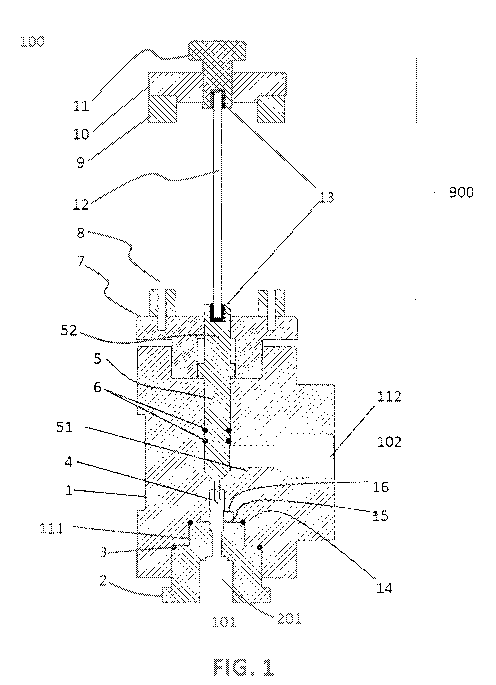
[011] FIG. 1 is a cross-sectional illustration of a pressure release valve,
and
[012] FIG. lA is a detail view of a pressure release valve.
[013] FIG. 2 is a cross-sectional illustration of a pressure release valve
including a buckling pin cartridge.
DESCRIPTION OF THE EMBODIMENTS
[014] Reference will now be made in detail to the present exemplary
embodiments, examples of which are illustrated in the accompanying figures.
[015] FIG. 1 illustrates one embodiment of an oil recovery valve 100. As
illustrated, the oil recovery valve 100 has an inlet 101 and an outlet 102.
The inlet
101 may be exposed to the pressurized system (e.g., a downhole oil recovery
pumping system), and the oil recovery valve 100 may be configured to allow
pressurized fluid to escape from the inlet 101 through the outlet 102 when the
valve
100 is opened.
[016] Oil recovery valve 100 may include a main body 1 having an inlet bore
111 and an outlet bore 1'12. An inlet member 2 may engage with the inlet bore
111.
For example, as illustrated in FIG. 1, the inlet member 2 may be at least
partially
inserted within the inlet bore 111 of main body 1, and one or more seals 3, 14
may
be provided to create a sealing engagement between the main body 1 and inlet
member 2. The inlet member 2 may include a central bore 201, which provides a
fluid flow path from the pressurized system to the main body 1. A sealing
mechanism 15 (e.g., a sealing cartridge), may be provided between the inlet
member
2 and the main body 1. The sealing mechanism 15 may be sealingly engaged with
the main body '1 and/or the inlet member 2 by way of a seal 16. The sealing
mechanism 15 further may be sealingly engaged with a floating bean tube 4. In
one
embodiment, a sealing mechanism 15 may be configured to float within the valve
body¨e.g., such that the sealing mechanism 15 may move coaxiaily with the tube
4;
however, in another embodiment, the sealing mechanism '15 may be secured to
the
valve body and constrained against moving with the tube 4.
- 4 -
CA 02947693 2016-10-31
WO 2015/168558 PCT/US2015/028802
[017] Although not illustrated in FIG, 1, the central bore 201 of the inlet
member 2 may be provided with an extension, tubing, or other feature to direct
fluid
into the valve. Sirnilariy, an extension, tubing, or other feature may be
provided with
outlet bore 112 to direct a released fluid away from the valve.
[018] The inlet member 2 may engage with the main body 1 by any suitable
means. For example, the inlet member 2 may have a threaded outer surface that
may be screwed into a mated threaded inner surface of the inlet bore 111. In
another embodiment, the inlet member 2 may have a flanged connection to the
main
body 1, wherein mated flanges of the inlet member 2 and main body 1 are
screwed,
clamped, or otherwise attached together.
[019] It may be desirable for the inlet member 2 to be easily removed from
the main body 1, so that it may be replaced. For example, the inlet member 2
may
be exposed to damaging high pressures, high heat, or corrosive conditions. In
the
event of damage due to such conditions, the valve 100 may be reconditioned by
replacing only inlet member 2 (rather than main body 1 or other components).
As
another example, making inlet member 2 replaceable rnay allow the same valve
100
to be adaptable to different environments or applications. For example, in
certain
applications, it may be sufficient for inlet member 2 to be fabricated from
steel;
whereas in other environments, it may be desirable for inlet member 2 to be
fabricated from a material (such as, e.g., Hastelloy) that is more resistant
to
corrosion or harsh conditions, Making the inlet member 2 easily replaceable
allows
the rest of the valve 100 components to be used for different applications
with a
simple substitution of the inlet member 2. As yet another example, it may be
desirable to replace the inlet member 2 to have a different diameter of
central bore
201 to optimize the rate or characteristics of fluid flow through the valve
100,
[020] A central bore 121 of the main body 1 has an upper portion shaped to
receive a piston plug 5. The piston plug 5 may be provided with one or more
seals 6
to ensure a fluid-tight, slidable relationship between the piston plug 5 and a
central
bore 121 of the main body 1. The central bore 121 also includes a lower
portion
shaped to receive the upper extent of a floating bean tube 4. As illustrated,
the lower
portion of the central bore 121 has a smaller diameter than the upper portion.
A
shoulder 122 (FIG. 1A) is provided between the upper and lower portions of the
central bore 121. The shoulder 122 is configured to prevent the floating bean
tube 4
from sliding upward beyond the shoulder 122.
- 5 -
CA 02947693 2016-10-31
WO 2015/168558 PCT/US2015/028802
[021] The central bore 201 of the inlet member 2 has an upper portion
shaped to receive the lower extent of a floating bean tube 4. As illustrated,
a
shoulder 202 (FIG. 1A) is provided to prevent the floating bean tube 4 from
sliding
downward beyond the shoulder 202.
[022] The central bores 121, 201 of the main body 1 and inlet member 2 are
aligned to forn-i a tube cavity 400. The floating bean tube 4 is positioned
within the
tube cavity 400. The floating bean tube 4 may slide a short distance relative
to the
main body 1 and inlet member 2 (i.e., within the tube cavity 400 between
shoulder 122 and shoulder 202), while maintaining a fluid-tight seal with the
main
body 1, sealing mechanism 15, and inlet member 2,
[023] A first end 51 of the piston plug 5 is engaged with an opening of the
the
floating bean tube 4 to plug the bean tube 4. In one embodiment, the first end
51
and floating bean tube 4 may be sealed together. According to this
arrangement, as
illustrated in FIG. 1, the combined piston plug 5 and bean tube 4 may remain
sealed
together while sliding relative to the main body 1 and the inlet member 2 for
a short
distance (i.e., the distance through which the bean tube 4 is allowed to
travel in the
tube cavity 400). As the piston plug 5 continues to slide upward, the shoulder
122
prevents bean tube 4 from further upward displacement, and the seal between
the
piston plug 5 and floating bean tube 4 may disengage to allow fluid to pass
from the
pressurized system through the bean tube 4 and out of the outlet 102 of the
valve.
[024] Although the first end 51 of the plug 5 is illustrated as having a "vee"
shape at its interface with the tube 4, the disclosure is not limited to that
configuration. For example, the first end 51 may terminate in a simple squared-
off
shape, such that a flat surface engages with an end of the tube 4. As another
example, the plug 5 and/or tube 4 may be designed to have a soft-seating
arrangment (e.g., using a non-metallic material). Further, the material of the
plug 5
and/or tube 4 may be selected depending on the nature of the application
and/or the
nature of the desired seal or other interaction between the plug 5 and/or tube
4. For
example, one or both components may be made from a metal, ceramic, plastic,
rubber, or other suitable material.
[025] FIG. 1 further illustrates a failure member assembly 900 mounted on
the main body 1. As shown, the failure member assembly 900 includes a failure
member cage 9, which has a bonnet section 7 and an end cap 10. As illustrated,
the
failure member cage 9 is secured to the bonnet section 7 via fasteners 8. The
end
- 6 -
CA 02947693 2016-10-31
WO 2015/168558 PCT/US2015/028802
cap 10 may also be secured to the failure member cage 9 by way of one or more
fasteners (not shown). In an embodiment wherein the failure rnember is a
buckling
pin, the failure member assembly 900 may be a buckling pin assembly and the
failure member cage 9 may be a buckling pin cage,
[026] According to one embodiment, the failure member assembly 900 may
be removed from the main body 1 and/or disassembled to provide easy access to
the piston plug 5 (e.g., for maintenance). For example, in one embodiment, the
bonnet section 7 and the main body 1 may have mated threaded portions, such
that
the bonnet section 7 may be screwed into and out of the main body 1. As
another
example, the bonnet section 7 may be attached to the main body 1 by way of
screws, clamps, latch assemblies, or any other suitable releasable attachment
rnechanisms, which may be released to permit access to the piston plug 5.
[027] A failure member 12 may be secured between an adjuster screw 11
and the second end 52 of the piston plug 5. The adjuster screw 11 may be used
to
pre-load the failure member 12 in compression. Additionally or alternatively,
the
adjuster screw may be used to facilitate installation of failure members of
different
lengths. In one or both of the adjuster screw 11 and second end 52 of the
piston
plug, a bushing 13 may be provided to facilitate engagement with the failure
member 12. Bushings 13 may be replaced or exchanged to allow failure members
of different diameters or shapes to be used.
[028] In one embodiment, the failure member 12 may be cylindrical (i.e., with
a consistent circular cross-section across the length of the member), e.g., a
cylindrical buckling pin. The present disclosure also contemplates using
failure
members with alternate configurations. For example, a failure member may have
a
polygonal cross-section (e.g., square, rectangular, triangular, octagonal) or
a
variable cross-section (e.g., square and circular cross-sections at different
locations).
A failure member may also be provided with surface features (e.g,, narrowed or
tapered portions, scored portions, or notches). A failure member 12 may be,
e.g., a
buckling pin configured to buckle in response to a predetermined stress. In
another
embodiment, another suitable component configured to fail in response to a
predetermined stress or strain may be used for the failure member 12 or in
place of
the failure member 12. For example, it is contemplated that a shear pin or
tension
pin may be used as a failure member, wherein the shear pin or tension pin is
configured to fail in response to a predetermined stress or strain. Et is
further
- 7 -
CA 02947693 2016-10-31
WO 2015/168558 PCT/US2015/028802
contemplated that a deformable failure member may be used, such as a spring,
Belleville spring, Belleville washer, collapsible bellows, cam release, or
other
mechanical release, configured to control the pressure at which a valve may
open. A
failure member 12 may be configured to allow a valve to open via irreversible
or,
alternatively, reversible deformation of the failure member.
[029] In one embodiment, a failure member may be provided as part of a
pre-assembled cartridge for ease of installation or replacement. For example,
a
failure member cartridge may include a failure member preassembled together
with
a failure member cage or failure member assembly. In one embodiment (not
shown), the piston plug 5 may also be included as part of the preassernbled
cartridge. As another example, illustrated in Fig. 2, a failure member 212 may
be
provided in a cartridge 230 separately from a failure member cage assembly
902.
The cartridge 230 may be secured within a cage 209 between an end cap 210 and
a
bonnet section 207, such that force from a piston 252 may be transferred to
the
failure member 212 within the cartridge 230.
[030] Using a cartridge assembly may facilitate adaptability of a valve. For
example, one cartridge may be replaced with elements of a different design to
accommodate different failure member designs (e.g., pins having different
material,
cross-section, profile, diameter, length, or surface features) to change the
activation
pressure range of the valve.
[031] Now turning to the operation of an oil recovery valve, the valve 100
may be installed with the inlet member 2 exposed to a pressurized system.
Pressure
applied to the inlet member 2 applies a force to the floating bean tube 4 and
the
piston plug 5. That force, in turn, is transferred to the failure member 12 in
the form
of a compressive load.
[032] As the pressure in the pressurized system fluctuates, the failure
member 12 may deform (without failing), which allows the piston plug 5 to move
a
short distance axially relative to the main body 1. In a known valve, such
displacement of a piston plug may allow undesirable leakage of fluid from the
pressurized system as the valve seal is repeatedly cracked open and shut.
According to the present disclosure, however, as the piston plug 5 moves a
short
distance, the floating bean tube 4 moves with it. In this manner, the sealing
surface
between piston plug 5 and floating bean tube 4 remains intact, and leakage is
prevented.
- 8 -
CA 02947693 2016-10-31
WO 2015/168558 PCT/US2015/028802
[033] When pressure in the pressurized system reaches a predetermined
level, the compressive force on the failure member 12 causes the failure
member to
fail (i.e., the valve is activated), which frees the piston plug 5 to slide
upward. The
floating bean tube 4, however, is constrained to slide only to the shoulder
122. Thus,
once the floating bean tube 4 has reached the full extent of its upward motion
and
the piston plug 5 continues to move upward, the seal between the floating bean
tube 4 and the piston plug 5 is broken. Pressurized fluid is thus allowed to
flow from
the valve inlet 101 through the floating bean tube 4 and out through the valve
outlet
102. Once the pressure within the pressurized system has been reduced to a
safe
level, the failure member 12 may be replaced as described above.
[034] While an oil recovery valve is described above, it is contemplated that
the disclosed valve may be used in other applications requiring overpressure
protection. Additionally, while a valve is described above as using a buckling
pin
release mechanism, the disclosure is not limited to that configuration. It is
contemplated that other release mechanisms may be used. For example, a piston
plug and floating bean tube may be used in combination with a release
mechanism
in the form of a shear pin, tension pin, spring. Belleville washer, Belleville
spring,
coilapsible bellows, or other suitable mechanism. The release mechanism may
utilize a deformable release mechanism, wherein deformation is irreversible
(e.g., a
buckling pin) or reversible (e.g., a spring). In addition, although a valve
configuration
is described above as transferring an axial force from a piston plug to a
buckling pin
release mechanism, it is also contemplated that the force from a piston plug
may be
translated into a rotational torque via a rotational member, and that a
release
mechanism may be configured to release in response to a predetermined level of
torque.
[035] It is contemplated that individual features of one embodiment may be
added to, or substituted for, individual features of another embodiment.
Accordingly,
it is within the scope of this disclosure to cover embodiments resulting from
substitution and replacement of different features between different
embodiments.
[036] The above described embodiments and arrangements are intended
only to be exemplary of contemplated systems and methods. Other embodiments
will be apparent to those skilled in the art from consideration of the
specification and
practice of the disclosure herein.
- 9