Sélection de la langue

Search

Sommaire du brevet 2947749 

Énoncé de désistement de responsabilité concernant l'information provenant de tiers

Une partie des informations de ce site Web a été fournie par des sources externes. Le gouvernement du Canada n'assume aucune responsabilité concernant la précision, l'actualité ou la fiabilité des informations fournies par les sources externes. Les utilisateurs qui désirent employer cette information devraient consulter directement la source des informations. Le contenu fourni par les sources externes n'est pas assujetti aux exigences sur les langues officielles, la protection des renseignements personnels et l'accessibilité.

Disponibilité de l'Abrégé et des Revendications

L'apparition de différences dans le texte et l'image des Revendications et de l'Abrégé dépend du moment auquel le document est publié. Les textes des Revendications et de l'Abrégé sont affichés :

  • lorsque la demande peut être examinée par le public;
  • lorsque le brevet est émis (délivrance).
(12) Brevet: (11) CA 2947749
(54) Titre français: MECANISMES DE POMPE PORTATIFS, ACCESSOIRES DE SCIE A CHAINE ET TROUSSES D'ACCESSOIRES DE POMPE DE SCIE A CHAINE
(54) Titre anglais: PORTABLE PUMP SYSTEMS, CHAINSAW ACCESSORIES, AND CHAINSAW PUMP ACCESSORY KITS
Statut: Accordé et délivré
Données bibliographiques
(51) Classification internationale des brevets (CIB):
  • A62C 25/00 (2006.01)
  • B27B 17/00 (2006.01)
  • F04D 1/00 (2006.01)
  • F04D 13/02 (2006.01)
(72) Inventeurs :
  • GLOVER, DILLON MICHAEL (Etats-Unis d'Amérique)
  • LINDSAY, BLAKE CATLIN (Etats-Unis d'Amérique)
(73) Titulaires :
  • BLAKE CATLIN LINDSAY
(71) Demandeurs :
  • BLAKE CATLIN LINDSAY (Etats-Unis d'Amérique)
(74) Agent: LAVERY, DE BILLY, LLP
(74) Co-agent:
(45) Délivré: 2024-06-25
(22) Date de dépôt: 2016-11-04
(41) Mise à la disponibilité du public: 2017-05-09
Requête d'examen: 2021-10-28
Licence disponible: S.O.
Cédé au domaine public: S.O.
(25) Langue des documents déposés: Anglais

Traité de coopération en matière de brevets (PCT): Non

(30) Données de priorité de la demande:
Numéro de la demande Pays / territoire Date
62/252,697 (Etats-Unis d'Amérique) 2015-11-09
62/326,643 (Etats-Unis d'Amérique) 2016-04-22

Abrégés

Abrégé français

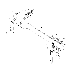
Il est décrit des systèmes de pompes à eau centrifuges pouvant comprendre une scie à chaîne avec un moteur, un papillon de gaz, un guide-chaîne de scie à chaîne, une tête de pompe à eau avec un tuyau daspiration et un tuyau de déversement et un dispositif de couplage configuré dans le but de connecter le guide-chaîne de scie à chaîne à la tête de pompe à eau, de manière fonctionnelle. Il est également décrit des accessoires de scie à chaîne pouvant comprendre une pompe centrifuge configurée dans le but dêtre couplée au guide-chaîne de scie à chaîne. Il est également décrit des trousses daccessoires de scie à chaîne pouvant comprendre une pompe centrifuge, des pointes de stabilisateur et une commande daccélérateur. Il est également décrit des méthodes dutilisation de scies à chaîne, de pompes et/ou de trousses.


Abrégé anglais

Centrifugal water pump systems are provided that can include: a chainsaw with a motor, a throttle, and a chainsaw bar; a water pump head with a suction pipe and a discharge pipe; and a coupling device configured to operably connect the chainsaw bar to the water pump head. Chainsaw accessories are also provided that can include a centrifugal pump configured to be coupled to the chainsaw bar. Chainsaw accessory kits are also provided that can include a centrifugal pump, stabilizer spikes, and a throttle control. Methods for using the chainsaws, pumps, and/or kits are also described.

Revendications

Note : Les revendications sont présentées dans la langue officielle dans laquelle elles ont été soumises.


CLAIMS
1. A chainsaw assembly comprising:
a motor housing;
a chainsaw bar having a proximal end connected to the motor and a
distal end;
a chainsaw chain surrounding the chainsaw bar;
a centrifugal pump including a drive configured to engage the
chainsaw chain or the chainsaw bar at the distal end, the centrifugal
pump further including a mounting bracket and a chainsaw bar stabilizer
connected to the mounting bracket, wherein the chainsaw bar is coupled
to the mounting bracket and the chainsaw saw bar is stabilized in a
position by the chainsaw bar stabilizer;
a set of stabilizer spikes comprising opposing pairs of spikes
configured to mount to the centrifugal pump; and
a throttle lock configured to hold a throttle of the chainsaw
assembly in an engaged position providing for handsfree operation of the
chainsaw assembly.
2. The chainsaw assembly of claim 1 wherein the set of stabilizer
spikes comprise a platform supporting the opposing pairs of spikes.
3. The chainsaw assembly of claim 2 wherein each pair of
opposing spikes is comprised by a single U-shaped member.
4. The chainsaw assembly of claim 3 wherein a center portion of
the U-shaped member rotatably engages the platform.
5. The chainsaw assembly of claim 4 wherein each of the opposing
pair of spikes is rotatable between a first position aligned practically
parallel with the platform and a second position aligned practically normal
to the platform.
9
Date Recue/Date Received 2023-04-17

6. The chainsaw assembly of claim 1 wherein a second set of
stabilizer spikes is configured to be coupled to the motor housing of the
chainsaw.
Date Recue/Date Received 2023-04-17

Description

Note : Les descriptions sont présentées dans la langue officielle dans laquelle elles ont été soumises.


Portable Pump Systems, Chainsaw Accessories, and Chainsaw Pump
Accessory Kits
TECHNICAL FIELD
[0001] Fire
fighters, particularly fire fighters that fight forest fires, can
find themselves surrounded by water, but without a way to convey the
water to the source of the fire. Often these brave souls have hiked miles
into the wilderness supplied only with what they can carry. What they can
carry typically includes a chainsaw, but does not include a water pump.
The present disclosure provides portable pump systems, chainsaw
accessories, and chainsaw pump accessory kits that can be used by
those that fight forest fires, for example.
BACKGROUND
[0002] Water pumps and chainsaws are two very important tools for
combatting wildfires. They are also extremely heavy for firefighters to
carry, especially when walking for miles into and around massive fires.
The energy of these brave public servants is probably the most valuable
tool in combatting large, destructive fires. Thus, with all of the equipment
that a firefighter already has to have to do his or her job, efficiency and
reduction of bulky equipment are paramount. The current disclosure
helps the firefighter by providing a centrifugal water pump that can be
attached to the bar of a chainsaw, eliminating the necessity of carrying
excessive gear, such as different fuel for different motors, extra oil, or an
attached engine. The increased efficiency from the present disclosure
1
Date Recue/Date Received 2023-04-17

can be beneficial for home defense, irrigation, or other uses, as well as
fighting fires.
DRAWI NGS
[0003] Embodiments of the disclosure are described below with
reference to the following accompanying drawings.
[0004] Fig. 1A depicts two perspective views of an embodiment of the
disclosure.
[0006] Fig. 1B depicts two perspective views of a different embodiment
of the present disclosure.
[0006] Fig. 2 is a perspective view of an embodiment of the disclosure.
[0007] Fig. 3 is a perspective view of a different embodiment of the
disclosure.
[0008] Fig. 4 is a deconstructed view of the components of a water
pump connection system, according to an embodiment of the disclosure.
[0009] Fig. 5 is a detailed view of the connection between a chainsaw
bar and driving rings, according to one embodiment of the disclosure.
[0010] Fig. 6 is a deconstructed view of operable connective pieces,
according to one embodiment of the disclosure.
[0011] Fig. 7 is a detailed view of operable connective pieces,
according to one embodiment of the disclosure.
2
Date Recue/Date Received 2023-04-17

[0012] Fig. 8A is a detailed view of the safety spike system, according
to an embodiment of the disclosure.
[0013] Fig. 8B is a detailed view of the safety spike system, according
to an embodiment of the disclosure.
[0014] Fig. 8C is a detailed view of the safety spike system, according
to an embodiment of the disclosure.
[0015] Fig. 9 is a perspective view of an embodiment of the disclosure.
[0016] Fig. 10 is a detailed view of the embodiment of the disclosure
shown in Fig. 9.
[0017] Fig. 11A is a detailed view of a portion of a water pump
connection system, according to an embodiment of the disclosure.
[0018] Fig. 11B is a detailed view of a portion of a water pump
connection system, according to an embodiment of the disclosure.
[0019] Fig. 12 is a detailed view of a throttle and throttle lock device of
a water pump system, according to an embodiment of the disclosure.
[0020] Fig. 13 is a perspective view of a water pump system packaged
for mobility, according to an embodiment of the disclosure.
DESCRIPTION
[0021] Centrifugal water pump systems, chainsaw accessories, and kits
are described with reference to Figs. 1A through 13.
3
Date Recue/Date Received 2023-04-17

[0022] In
accordance with these Figures and this disclosure, centrifugal
water pump systems are provided that can include: a chainsaw with a
motor, a throttle, and a chainsaw bar; a water pump head with a suction
pipe and a discharge pipe; and a coupling device configured to operably
connect the chainsaw bar to the water pump head. Chainsaw
accessories are also provided that can include a centrifugal pump
configured to be coupled to the chainsaw bar. Chainsaw accessory kits
are also provided that can include a centrifugal pump, stabilizer spikes,
and a throttle control. Methods for using the chainsaws, pumps, and/or
kits are also described.
[0023] Referring to Figs. 1A and 1B, embodiments of a water pump
system 10 are shown. Fig. 1A depicts a perspective view of a chainsaw
bar 16 coupled to a water pump head 12 by a coupling device 14. Fig. 1A
also depicts this configuration from a perspective view from the end of
the chainsaw bar 16, showing the same components, a water pump head
12 and a coupling device 14. Fig. 1B depicts two perspective views of a
different embodiment of the disclosure, wherein the coupling device 14A
sits at a different position on the water head pump 12, which can be
lower. In this embodiment, there is a chain 18 on the chainsaw bar 16.
The chain 18 can be connected to the coupling device 14A.
[0024]
Referring next to Fig. 2, a centrifugal water pump system is
shown with a chainsaw motor 50 connected to a chainsaw bar 16 and a
throttle 46. The chainsaw bar is coupled to a water pump head 12 having
a handle 42 and a discharge pipe 44. The chainsaw bar 16 is coupled to
4
Date Recue/Date Received 2023-04-17

the water pump head 12 by a mounting bracket 40 and a mounting
bracket bolt 54, and the chainsaw bar is stabilized in this position by a
chainsaw bar stabilizer 52 and a chainsaw stabilizer bolt 56. Fig. 2 also
depicts water pump safety spikes 22 positioned below the water pump
head 12 and secured to the water pump head 12 by a water pump safety
spike mount 24. The chainsaw motor 50 is also coupled to chainsaw
head safety spikes 32 by a chainsaw head safety spike mount 34.
[0025]
Referring next to Fig. 3, a different configuration of a centrifugal
water pump system is shown. In this configuration, a chainsaw bar 16 is
surrounded by a chain guard 17. In this
configuration, a coupling device
14 fastens the chainsaw bar 16 to a water pump head 12 that has a
handle 42 and discharge pipe 44. A chainsaw motor head 50 connects to
the chainsaw bar 16. The chainsaw motor head 50 has a throttle 46 and
is connected to a chain break release 58 that fastens to the chain guard
17. Fig. 3
also depicts chainsaw safety spikes 32 coupled to the
chainsaw motor 50 by a chainsaw safety spike mount 34.
[0026]
Referring next to Fig. 4, the components of a centrifugal water
pump system are shown. A chainsaw motor 50 having a throttle 46 is
shown; a chain brake release 58 is shown. The chainsaw motor is
coupled to chainsaw head safety spikes 32 by a chainsaw head safety
spike mount 34. A chainsaw bar 16 is surrounded by a chain guard 17. A
second side of a chainsaw bar 16A is shown, coupled with a female drive
ring 64 and drive ring adapter 66 configured to couple with a male drive
ring 68. Fig. 4 also depicts a water pump head 12 that has a suction pipe
Date Recue/Date Received 2023-04-17

43 and a discharge pipe 44. Fig. 4 also depicts water pump safety spikes
22 attached to a water pump safety spike mount 24.
[0027] Referring next to Fig. 5, a detailed view of the components of an
embodiment of the disclosure is shown. A chainsaw bar 16 is operably
coupled with a side of a chainsaw bar 16A by a male drive ring 68
connected to a drive ring adapter 66 and a female drive ring 64. A
spurred drive ring gear 62 circles the drive ring adapter 66. The spurred
drive ring gear 62 is configured to capture a chainsaw chain.
[0028] Referring next to Fig. 6, a water pump head 12 with a discharge
pipe 44 and a handle 42 is shown. Also shown is a mounting bracket 40
connected to a chainsaw bar stabilizer 52 and a coupling device 14. For
adaptation configurations, a drive sprocket 72 and a spline adapter for
capturing a chainsaw chain may be utilized as shown. Referring next to
Fig. 7, the components of a centrifugal water pump system are shown. A
chainsaw bar 16 and a chain guard 17 are shown, as well as a water
pump head 12 with a handle 42 and a discharge pipe 44. Connecting the
chainsaw bar 16 to the water pump head 12 are the components, a drive
sprocket 72, a mounting bracket 40, a coupling device 14, and a male
drive ring 68.
[0029] Referring next to Figs. 8A, 8B, and 8C, configurations of safety
spikes 22 and 22A and a safety spike mount 24 are shown. Fig. 8A
depicts safety spikes 22 and 22A connected to safety spike mount 24 in
operating position, with safety spikes 22 and 22A opened to be parallel
with each other and perpendicular to safety spike mount 24. Fig. 8A is
6
Date Recue/Date Received 2023-04-17

configured to be planted into the ground and secure the pump and/or
chainsaw motor during operation. Fig. 8B depicts a perspective view of
the safety spike configuration collapsed, where each of the safety spikes
22 and 22A rotates in the same angular direction so that safety spike 22
sits essentially flush with the safety spike mount 24, and safety spike 22A
sits essentially flush with the safety spike mount 24, but on the opposite
side of safety spike mount 24 from safety spike 22, when in the collapsed
position. Fig. 8C depicts a perspective of the collapsed safety spikes 22
and 22A on either side of the safety spike mount 24.
[0030] Referring next to Figs. 9 and 10, a centrifugal water pump
system is shown. A chainsaw motor 50 has a throttle 46 coupled to a
throttle lock device 48 and is supported by chainsaw head safety spikes
32. Connected to the chainsaw motor 50 is a chainsaw bar 16 which is
secured to a chainsaw bar stabilizer 52 by a chainsaw stabilizer bolt 56.
Also coupled to the chain guard 17 is a water pump head 12, which is
coupled to the chainsaw bar 17 by a mounting bracket 40 and a mounting
bracket bolt 54. This end of the water pump system is supported by
water pump safety spikes 22, as shown in Fig. 10, a detailed view of Fig.
9. The water pump spikes 22 are connected to the water pump head 12
by a water pump spike mount 24. Fig. 10 also depicts the chainsaw bar
16 coupled to a mounting bracket 40 and water pump head 12.
[0031] Referring next to Figs. 11A and 11B, Fig. 11A depicts the water
pump head 12 with a handle 42 and a discharge pipe 44. The water
pump head 12 is connected to a chainsaw bar 16 by a mounting bracket
7
Date Recue/Date Received 2023-04-17

40 and a mounting bracket bolt 54. The chainsaw bar 16 is also coupled
to a chainsaw bar stabilizer 52 by a chainsaw stabilizer bolt 56. The
water pump head 12 is supported in this embodiment by water pump
safety spikes 22, which are coupled to the water pump head 12 by a
water pump safety spike mount 24. Fig. 11B depicts a detailed view of a
chainsaw motor 50 connected to a chainsaw bar 16. The chainsaw motor
has a throttle 46 which is coupled to a chainsaw head safety spike mount
34. The chainsaw head safety spike mount 34 is coupled to chainsaw
head safety spikes 32, which support the chainsaw motor 50 when
planted in the ground during operation.
[0032]
Referring next to Fig. 12, a detailed view of a throttle 46 is
shown. The throttle 46 is connected to a chainsaw motor 50. The throttle
46 is coupled to a chainsaw head safety spike mount 34. The chainsaw
head safety spike mount 34 is connected to chainsaw head safety spikes
32. The throttle is further coupled to a throttle lock device 48 for hands-
free consistent motor operation.
[0033] Referring next to Fig. 13, a water pump system 70 is shown in a
portable kit configuration. In the system 70, a safety spike system 30 can
be contained, along with a pump head 76 which can contain a water
pump head and connective accessories, and throttle control 49 which can
contain a throttle control and connective accessories.
8
Date Recue/Date Received 2023-04-17

Dessin représentatif
Une figure unique qui représente un dessin illustrant l'invention.
États administratifs

2024-08-01 : Dans le cadre de la transition vers les Brevets de nouvelle génération (BNG), la base de données sur les brevets canadiens (BDBC) contient désormais un Historique d'événement plus détaillé, qui reproduit le Journal des événements de notre nouvelle solution interne.

Veuillez noter que les événements débutant par « Inactive : » se réfèrent à des événements qui ne sont plus utilisés dans notre nouvelle solution interne.

Pour une meilleure compréhension de l'état de la demande ou brevet qui figure sur cette page, la rubrique Mise en garde , et les descriptions de Brevet , Historique d'événement , Taxes périodiques et Historique des paiements devraient être consultées.

Historique d'événement

Description Date
Inactive : Octroit téléchargé 2024-06-26
Accordé par délivrance 2024-06-25
Lettre envoyée 2024-06-25
Inactive : Page couverture publiée 2024-06-24
Préoctroi 2024-05-13
Inactive : Taxe finale reçue 2024-05-13
Lettre envoyée 2024-01-15
Un avis d'acceptation est envoyé 2024-01-15
Inactive : Approuvée aux fins d'acceptation (AFA) 2024-01-03
Inactive : Q2 réussi 2024-01-03
Inactive : Changmnt/correct nom refusé-Corr envoyée 2023-05-08
Inactive : Changmnt/correct de nom fait-Corr envoyée 2023-05-08
Modification reçue - modification volontaire 2023-04-17
Modification reçue - réponse à une demande de l'examinateur 2023-04-17
Inactive : Correspondance - Formalités 2023-04-06
Inactive : Conformité - Formalités: Réponse reçue 2023-04-06
Demande de correction du demandeur reçue 2023-04-06
Lettre envoyée 2023-04-06
Inactive : Transfert individuel 2023-04-06
Rapport d'examen 2023-01-09
Inactive : Rapport - Aucun CQ 2023-01-04
Lettre envoyée 2021-11-03
Toutes les exigences pour l'examen - jugée conforme 2021-10-28
Exigences pour une requête d'examen - jugée conforme 2021-10-28
Requête d'examen reçue 2021-10-28
Représentant commun nommé 2019-10-30
Inactive : Regroupement d'agents 2018-09-01
Inactive : Regroupement d'agents 2018-08-30
Demande publiée (accessible au public) 2017-05-09
Inactive : Page couverture publiée 2017-05-08
Inactive : CIB attribuée 2016-12-18
Inactive : CIB en 1re position 2016-12-18
Inactive : CIB attribuée 2016-12-18
Inactive : CIB attribuée 2016-12-12
Exigences de dépôt - jugé conforme 2016-11-10
Inactive : Certificat dépôt - Aucune RE (bilingue) 2016-11-10
Demande reçue - nationale ordinaire 2016-11-09
Déclaration du statut de petite entité jugée conforme 2016-11-04

Historique d'abandonnement

Il n'y a pas d'historique d'abandonnement

Taxes périodiques

Le dernier paiement a été reçu le 2023-11-03

Avis : Si le paiement en totalité n'a pas été reçu au plus tard à la date indiquée, une taxe supplémentaire peut être imposée, soit une des taxes suivantes :

  • taxe de rétablissement ;
  • taxe pour paiement en souffrance ; ou
  • taxe additionnelle pour le renversement d'une péremption réputée.

Veuillez vous référer à la page web des taxes sur les brevets de l'OPIC pour voir tous les montants actuels des taxes.

Historique des taxes

Type de taxes Anniversaire Échéance Date payée
Taxe pour le dépôt - petite 2016-11-04
TM (demande, 2e anniv.) - petite 02 2018-11-05 2018-11-01
TM (demande, 3e anniv.) - petite 03 2019-11-04 2019-10-29
TM (demande, 4e anniv.) - petite 04 2020-11-04 2020-10-29
Requête d'examen - petite 2021-11-04 2021-10-28
TM (demande, 5e anniv.) - petite 05 2021-11-04 2021-10-29
TM (demande, 6e anniv.) - petite 06 2022-11-04 2022-10-11
Enregistrement d'un document 2023-04-06 2023-04-06
TM (demande, 7e anniv.) - petite 07 2023-11-06 2023-11-03
Taxe finale - petite 2024-05-13
Titulaires au dossier

Les titulaires actuels et antérieures au dossier sont affichés en ordre alphabétique.

Titulaires actuels au dossier
BLAKE CATLIN LINDSAY
Titulaires antérieures au dossier
DILLON MICHAEL GLOVER
Les propriétaires antérieurs qui ne figurent pas dans la liste des « Propriétaires au dossier » apparaîtront dans d'autres documents au dossier.
Documents

Pour visionner les fichiers sélectionnés, entrer le code reCAPTCHA :


Pour visualiser une image, cliquer sur un lien dans la colonne description du document. Pour télécharger l'image (les images), cliquer l'une ou plusieurs cases à cocher dans la première colonne et ensuite cliquer sur le bouton "Télécharger sélection en format PDF (archive Zip)" ou le bouton "Télécharger sélection (en un fichier PDF fusionné)".

Liste des documents de brevet publiés et non publiés sur la BDBC .

Si vous avez des difficultés à accéder au contenu, veuillez communiquer avec le Centre de services à la clientèle au 1-866-997-1936, ou envoyer un courriel au Centre de service à la clientèle de l'OPIC.


Description du
Document 
Date
(aaaa-mm-jj) 
Nombre de pages   Taille de l'image (Ko) 
Dessin représentatif 2024-05-23 1 8
Page couverture 2024-05-23 1 40
Dessin représentatif 2024-01-03 1 9
Revendications 2023-04-17 2 55
Description 2016-11-04 10 310
Abrégé 2016-11-04 1 16
Revendications 2016-11-04 3 71
Dessins 2016-11-04 13 160
Page couverture 2017-04-05 2 39
Dessin représentatif 2017-04-05 1 5
Description 2023-04-17 8 384
Certificat électronique d'octroi 2024-06-25 1 2 527
Taxe finale 2024-05-13 4 91
Certificat de dépôt 2016-11-10 1 201
Rappel de taxe de maintien due 2018-07-05 1 112
Courtoisie - Réception de la requête d'examen 2021-11-03 1 420
Courtoisie - Certificat d'enregistrement (document(s) connexe(s)) 2023-04-06 1 362
Avis du commissaire - Demande jugée acceptable 2024-01-15 1 580
Nouvelle demande 2016-11-04 6 270
Requête d'examen 2021-10-28 4 91
Demande de l'examinateur 2023-01-09 4 262
Modification au demandeur/inventeur / Correspondance de conformité / Correspondance reliée aux formalités 2023-04-06 8 168
Courtoisie - Accusé de correction d’une erreur dans le nom 2023-05-08 1 227
Courtoisie - Demande non conforme visant la correction d’une erreur dans le nom 2023-05-08 2 246
Modification / réponse à un rapport 2023-04-17 17 498