Sélection de la langue

Search

Sommaire du brevet 2948089 

Énoncé de désistement de responsabilité concernant l'information provenant de tiers

Une partie des informations de ce site Web a été fournie par des sources externes. Le gouvernement du Canada n'assume aucune responsabilité concernant la précision, l'actualité ou la fiabilité des informations fournies par les sources externes. Les utilisateurs qui désirent employer cette information devraient consulter directement la source des informations. Le contenu fourni par les sources externes n'est pas assujetti aux exigences sur les langues officielles, la protection des renseignements personnels et l'accessibilité.

Disponibilité de l'Abrégé et des Revendications

L'apparition de différences dans le texte et l'image des Revendications et de l'Abrégé dépend du moment auquel le document est publié. Les textes des Revendications et de l'Abrégé sont affichés :

  • lorsque la demande peut être examinée par le public;
  • lorsque le brevet est émis (délivrance).
(12) Brevet: (11) CA 2948089
(54) Titre français: DISPOSITIF D'ENFERMEMENT DE L'EXTREMITE D'UN OU DE PLUSIEURS FAISCEAUX DE MATIERE MOLLE DANS UN TUNNEL OSSEUX
(54) Titre anglais: DEVICE FOR TRAPPING THE END OF AT LEAST ONE FASCICLE OF SOFT MATERIAL IN A BONE TUNNEL
Statut: Accordé et délivré
Données bibliographiques
(51) Classification internationale des brevets (CIB):
  • A61F 02/08 (2006.01)
(72) Inventeurs :
  • ABASCAL RUBIO, JOSE MANUEL (Espagne)
  • ABASCAL AZANZA, JUAN (Espagne)
(73) Titulaires :
  • ABANZA TECNOMED, S.L.
(71) Demandeurs :
  • ABANZA TECNOMED, S.L. (Espagne)
(74) Agent: PERRY + CURRIER
(74) Co-agent:
(45) Délivré: 2021-04-27
(86) Date de dépôt PCT: 2014-07-21
(87) Mise à la disponibilité du public: 2015-11-12
Requête d'examen: 2019-07-19
Licence disponible: S.O.
Cédé au domaine public: S.O.
(25) Langue des documents déposés: Anglais

Traité de coopération en matière de brevets (PCT): Oui
(86) Numéro de la demande PCT: PCT/ES2014/070588
(87) Numéro de publication internationale PCT: ES2014070588
(85) Entrée nationale: 2016-11-04

(30) Données de priorité de la demande:
Numéro de la demande Pays / territoire Date
P201430688 (Espagne) 2014-05-09

Abrégés

Abrégé français

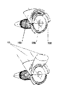
La présente invention concerne un dispositif d'enfermement de l'extrémité d'un ou de plusieurs faisceaux (10) de matière molle dans un tunnel osseux (1) qui comprend: un culot (100), une vis (200) et une rondelle (300); le culot présentant un rebord proximal supérieur (140) et des éléments de filet (150), avec un axe longitudinal (151) incliné de a degrés par rapport à l'axe longitudinal (101) du culot et du filet intérieur (152) réciproque au filet extérieur (201) de la vis, l'ensemble étant configuré de sorte que, quand on tourne la vis avec la rondelle dans le filet intérieur (152), la face externe (301) de la rondelle (300) se rapproche de la face interne (142) du rebord proximal supérieur (140), ce qui définit entre eux deux un passage supérieur par où dépasse la matière molle qui est ainsi retenue.


Abrégé anglais

The invention relates to a device for trapping the end of at least one fascicle (10) of soft material in a bone tunnel (1), comprising: a ferrule (100), a screw (200) and a washer (300), the ferrule comprising a proximal upper rim (140) and screwing elements (150), with a longitudinal axis (151) inclined a degrees in relation to the longitudinal axis (101) of the ferrule, and an inner thread (152) reciprocal to the outer thread (201) of the screw, the assembly being designed such that as the screw, with the washer, screws into the inner thread (152), the outer face (301) of the washer (300) approaches the inner face (142) of the proximal upper rim (140), an upper passage being formed between the two, via which the soft material projects, which is trapped in this way.

Revendications

Note : Les revendications sont présentées dans la langue officielle dans laquelle elles ont été soumises.


6
CLAIMS
1. A device for trapping the end of at least one fascicle
(10) of soft material in a bone tunnel (1), characterized in
that it comprises:
- a ferrule (100) having an outer diameter similar to that of
the bone tunnel,
- a screw (200) having an outer thread (201) and
- a washer (300) having an outer face (301),
the ferrule comprising:
- a longitudinal conduit (110) extended along in a first
longitudinal axis (101),
- a distal end (120),
- a proximal end (130),
- a proximal edge (131),
- a proximal upper rim (140) having an inner face (142) and
- screwing elements (150) with an inner thread (152),
extended along in a second longitudinal axis (151),
with the second longitudinal axis (151) inclined a degrees
in relation to the first longitudinal axis (101) of the ferrule,
and the inner thread (152) being reciprocal to the outer thread
(201) of the screw (200),
wherein
the device for trapping is configured such that as the
screw (200), with the washer (300), screws into the inner thread
(152), the outer face (301) of the washer (300) approaches the
inner face (142) of the proximal upper rim (140), an upper
passage being configured between both of them, whereby the soft
material projects, said soft material being thereby trapped.
2. The device for trapping according to claim 1,
characterized in that
- both the head (210) of rhe screw (200) and the washer (300)
are configured in frustoconical shapes of between 60' and
120',
Date reçue/Date Received 2020-12-04

7
- the washer (300) surrounding the perimeter (211) of the head
(210) of the screw like a sleeve,
- the inner face (142) of the proximal upper rim (140) being
configured in a reciprocal manner in an arched frustoconical
or frusto-conoid shape, the second longitudinal axis (151)
of which in turn has an inclination of between 300 and 60
in relation to the first longitudinal axis (101) of the
ferrule (100).
3. The device for trapping according to claim 1 or claim
2, characterized in that there are grooves (170) on the inner
face (142) of the proximal upper rim (140) for the purpose of
reinforcing the trapping of soft material.
4. The device for trapping according to any one of claims
1 - 3, characterized in that on both sides of the proximal edge
(131) of the ferrule (100) there are respective concave recesses
(180) through which part of the head (210) of the screw (200)
and of the washer (300) projects, a maximum clamping position
being reached when the washer (300) comes into contact with an
inner face of the proximal end (130) of the ferrule (100).
5. The device for trapping according to any one of claims
1 - 4, characterized in that between the washer (300) and the
head of the screw (200) there are fitting elements (310)
preventing their separation.
6. The device for trapping according to any one of claims
1 - 5, characterized in that that the inner thread (152) is
configured on the inner side and lower walls of the ferrule
(100), truncated in the upper part thereof.
7. The device for trapping according to any one of claims
1 - 6, characterized in that the distal end (120) of the ferrule
(100) has oblique ending, to facilitate the introduction of the
ferule (100) into the bone tunnel.
8. The device for trapping according to any one of claims
1 - 7, characterized in that for each ferrule (100) there is a
milling key (400) with a handle (410), a rod (420) and a distal
coupling (430) in which there is a milling guide consisting of
Date reçue/Date Received 2020-12-04

8
a conduit (431) that maintains a relative position in relation
to the longitudinal axis and to a countersinking of the bone
tunnel identical to that of the longitudinal axis (151) of the
ferrule (100) to be used.
9. The device for trapping according to any one of claims
1 - 8, characterized in that for each ferrule (100) there is a
provisional trapping wedge (500) for trapping soft material (10)
consisting of an acute-angled distal end (501), a smooth dorsal
face (502) coming into contact with the soft material, a ventral
face (503) with steps (504) encased in the lower part of the
inner thread (152) of the ferrule (100) and a proximal end with
gripping elements (505) to facilitate handling of the
provisional trapping wedge (500) both for a provisional securing
of soft material and for a withdrawal thereof.
10. The device for trapping according to any one of claims
1 - 9, characterized in that it is made from a polymer material.
11. The device for trapping according any of claims J. -
10, wherein the ferrule and the screw and the washer being made
from a biocompatible material or biocompatible materials.
12. A device for trapping the end of at least one fascicle
(10) of soft material in a bone tunnel (1), characterized in
thal. it comprises:
a ferrule (100) having an outer diameter configured to be
similar to that of the bone tunnel,
a screw (200) having a head and an outer thread (201), and
a washer (300) having an outer face (301), the ferrule
comprising:
a hollow longitudinal conduit (110) extended along in a
first longitudinal axis (101), the longitudinal conduit being
configured to house said at least one fascicle,
a distal end (120),
a proximal end (130),
a proximal edge (131),
a proximal upper rim (140) having an inner face (142) and
an opening (150) with an inner thread (152), extended
Date recue/Date Received 2020-12-04

9
along in a second longitudinal axis (151),
with the second longitudinal axis (151) inclined a degrees
in relation to the first longitudinal axis (101) of the ferrule,
and the inner thread (152) being reciprocal to the outer thread
(201) of the screw (200),
wherein
the device for trapping is configured such that as the
screw (200), with the washer (300), screws into the inner thread
(152), the outer face (301) of the washer (300) approaches the
inner face (142) of the proximal upper rim (140), an upper
passage being configured between both of them, whereby the soft
material projects, said soft material being thereby trapped and
housed in the hollow longitudinal conduit and the upper passage.
13. The device for trapping according to claim 12,
characterized in that
both the head (210) of the screw (200) and the washer (300)
are configured in frustoconical shapes of between 60' and 120,
the washer (300) surrounding a perimeter (211) of the head
(210) of the screw like a sleeve,
the inner face (1.42) of the proximal upper rim (140) being
configured in a reciprocal manner in an arched frustoconical or
frusto-conoid shape, the second longitudinal axis (151) of which
in turn has an inclination of between 30' and 60' in relation
to r_he first longitudinal axis (101) of the ferrule (100).
14. The device for trapping according to claim 12,
characterized in that there are grooves (170) on the inner face
(142) of the proximal upper rim (140) for the purpose of
reinforcing the trapping of soft material.
15. The device for trapping according to claim 12,
characterized in that the proximal edge comprises two sides and
Date reçue/Date Received 2020-12-04

10
on both sides of the proximal edge (131) of the ferrule (100)
there are respective concave recesses (180) through which part
of the head (210) of the screw (200) and of the washer (300)
projects, a maximum clamping position being reached when the
washer (300) comes into contact with an inner face of the
proximal end (130) of the ferrule (100).
16. The device for trapping according to claim 12,
characterized in that between the washer (300) and the head of
the screw (200) there are fitting elements (310) preventing
their separation.
17. The device for trapping according to claim 12,
characterized in that the inner thread (152) is configured on
an inner side and lower walls of the ferrule (100), truncated
in an upper part thereof.
18. The device for trapping according to claim 12,
characterized in that the distal end (120) of the ferrule (100)
has an oblique ending, to facilitate the introduction of the
ferule (100) into the bone tunnel.
19. The device for trapping according to claim 12,
characterized in that for the ferrule (100) there is a
provisional trapping wedge (500) for trapping soft material (10)
consisting of an acute-angled distal end (501), a smooth dorsal
face (502) coming into contact with the soft material, a ventral
face (503) with steps (504) encased in the lower part of the
inner thread (152) of the ferrule (100) and a proximal end with
gripping elements (505) to facilitate handling of the
provisional trapping wedge (500) both for a provisional securing
of soft material and for a withdrawal thereof.
20. The device tor trapping according to claim 12,
characterized in that the ferrule is made from a polymer
Date reçue/Date Received 2020-12-04

11
material.
21. The device for trapping according to claim 20,
characterized in that the ferrule is made from a radio
transparent polymer material.
22. The device for trapping according to claim 12, wherein
the ferrule, the screw, and the washer are made from a
biocompatible material or biocompatible materials.
23. The device for trapping according to claim 12, wherein
the washer (300) is prolonged into at least one projection (320).
24. The device far trapping according to claim 12, wherein
there is in the screw a central longitudinal conduit (202)
through which a guide is introduced for screwing.
25. The device tor trapping according to claim 1,
characterized in that bath the head (210) af the screw (200)
and the washer (300) are configured in frustoconical shapes of
90 .
26. The device for trapping according to claim 1,
characterized in that the second longitudinal axis (151) has an
inclination of 45 in relation to the first longitudinal axis
(101) of the ferrule (100).
27. The device for trapping according to claim 10, wherein
the polymer material comprises a radio transparent polymer
material.
28. The device for trapping according to claim 1, wherein
the washer (300) is prolonged into at least one projection (320).
Date recue/Date Received 2020-12-04

12
29. The device for trapping according to claim. 6,
wherein in the screw there is a central longitudinal conduit
(202 through which a guide is introduced for screwing.
Date recue/Date Received 2020-12-04

Description

Note : Les descriptions sont présentées dans la langue officielle dans laquelle elles ont été soumises.


CA 02948089 2016-11-04
DEVICE FOR TRAPPING THE END OF AT LEAST ONE FASCICLE OF SOFT
MATERIAL IN A BONE TUNNEL
Object of the invention
The present invention relates to the field of traumatology,
specifically to a device for trapping the end of at least one
fascicle of soft material in a bone tunnel.
The object of the present invention is to provide a simple,
precise and reliable device that allows trapping, with
sufficient retaining force, without damaging soft tissue, the
end of at least one fascicle of soft material in a bone tunnel.
Background of the Invention
Tearing of soft material of the joints is very common, the
most common being tearing of the anterior cruciate ligament (ACL)
of the knee: grafts the ends of which are inserted in tibial and
femoral bone tunnels are used for replacement thereof.
Compared to the use of bone-tendon-bone grafts, soft
material grafts, autografts, allografts or synthetic grafts are
used increasingly more often, which grafts at the femoral level
are secured by means of transverse or suspension devices and at
the tibial level they are secured by means of interference
screws or washers with transtibial screws, which have the
advantage of leaving the healing perimeter free and of providing
a greater retaining force compared with interference screws.
In single tibial-femoral tunnel surgical techniques, in
which the fascicles of soft material are suspended at the
femoral level, the washer with a single transtibial screw is a
very reliable solution at the tibial level; however, in new
techniques that achieve restoring the helical anatomy of the
original cruciate ligament by means of three femoral tunnels and
three tibial tunnels, it would be necessary to use three long
transtibial screws, which is not acceptable.
Description of the Invention
To be able to provide devices for trapping by means of a
washer and screw which sufficiently clamp the fascicles of soft
material, each of them in its own bone tunnel, without having to

CA 02948089 2016-11-04
2
use long transtibial screws, the authors propose a new device
for trapping by means of a ferrule which is introduced in the
inlet opening of the bone tunnel, providing a screwing element
for a frustoconical screw with an also frustoconical washer
surrounding the head of the screw like a sleeve, the assembly
configured such that as the screw, with the washer, screws into
the ferrule, the outer face of the washer approaches the
proximal inner face of a proximal upper rim existing in the
ferrule, the soft material passing therethrough thereby being
strongly trapped.
The new cone-shaped clamping configuration that is proposed
allows exerting a great retaining force on the soft material,
which notably increases on one hand because the ferrule is
designed such that before the soft material is secured, it is
folded over the inner face of the proximal upper rim, and on the
other hand because it is contemplated that once the soft
material is tensed and secured, the remaining material is cut
and cauterized, forming a stump.
An additional objective of the present invention is to
provide devices for trapping soft material that are easy to use,
that do not damage the soft material and that do not project
from the inlet opening of the bone tunnel.
Description of the Drawings
To complement the description and for the purpose of
helping to better understand the features of the invention
according to a preferred practical embodiment thereof, a set of
drawings is attached as an integral part of said description, in
which the following is depicted:
Figure 1. In the upper part overall view of the device for
trapping; in the lower part view of the device trapping a
fascicle of soft material.
Figure 2. Disassembled view of the device for trapping
consisting of a ferrule, screw and washer.
Figure 3. Exploded view of the device for trapping and of
the countersunk edge of the inlet opening into the bone tunnel
in which the ferrule is incased.

CA 02948089 2016-11-04
3
Figure 4. Section view of the ferrule.
Figure 5. In the upper part section view of the screw and
washer; in the central part section view of the screw and washer
with a rim; in the lower part section view of the screw and
washer with a rim and with projections.
Figure 6. Section view of the ferrule incased in the bone
tunnel, with the screw and washer screwed together, trapping the
soft material.
Figure 7. In the upper part view of the milling key
opposite inlet opening of the bone tunnel; in the lower part
once it is introduced in the bone.
Figure B. In the upper part view of the wedge for trapping
and of the ferrule ; in the lower part view of the wedge
introduced in the ferrule, trapping the soft material.
Preferred Embodiment of the Invention
The preferred embodiment of the invention consists of a
device for trapping the end of at least one fascicle (10) of
soft material in a bone tunnel (1) comprising: a ferrule (100)
having an outer diameter similar to that of the bone tunnel, a
screw (200) and a washer (300), the three elements being shown
assembled together in the upper part of Figure 1 and
disassembled in Figure 2, the ferrule existing: a longitudinal
axis (101), a longitudinal conduit (110), a distal end (120), a
proximal end (130), a proximal edge (131), a proximal upper rim
(140) and screwing elements (150), with a longitudinal axis (151)
inclined a degrees in relation to the longitudinal axis (101) of
the ferrule and inner thread (152) reciprocal to the outer
thread (201) of the screw, the assembly being configured such
that as the screw, with the washer, screws into the inner thread
(152), the outer face (301) of the washer (300) approaches the
inner face (142) of the proximal upper rim (140), an upper
passage being configured between both of them, whereby the soft
material projects, said soft material being thereby trapped, as
shown in the lower part of Figure 1 and in a section view in
Figure 6, both the ferrule and the screw and the washer being
made from a biocompatible material or biocompatible materials;

4
both the head (210) of the screw (200) and the washer (300) being
configured in the preferred embodiment in frustoconical shapes of
between 60 and 120 , preferably 90 , the washer (300) surrounding the
perimeter (211) of the head (210) of the screw like a sleeve, the
inner face (142) of the proximal upper rim (140) being configured in a
reciprocal manner in an arched frustoconical or frusto-conoid shape,
with a longitudinal axis (141) coinciding with the longitudinal axis
(151) of the screwing element (150), the longitudinal axis (151) of
which in turn has an inclination of between 30 and 60 in relation to
the longitudinal axis (101) of the ferrule, preferably an inclination
of 45'; the washer (300) optionally being prolonged into at least one
projection (320) abutting with the cortical bone surrounding the inlet
into the bone tunnel; there being grooves (170) on the inner face (142)
of the proximal upper rim (140) for the purpose of reinforcing the
trapping of soft material; there being on both sides of the proximal
edge (131) of the ferrule (100) respective concave recesses (180)
through which part of the head (210) of the screw (200) and of the
washer (300) projects in the maximum clamping position; there being
between the washer (300) and the head of the screw (200) fitting
elements (310) preventing their separation, both at the time of their
placement and when they are withdrawn, as shown in the lower part of
Figure 5; the screwing elements consisting of an inner thread (152)
that is configured on the inner side and lower walls of the ferrule
(100), truncated in the upper part thereof, there being in the screw a
rounded-tip end (202); the distal end (120) of the ferrule (100)
having an oblique ending, making the introduction thereof into the
bone tunnel easier; there being for each ferrule (100) a milling key
(400) with a handle (410), a rod (420) and a distal coupling (430) in
which there is a milling guide consisting of a conduit (431) that
maintains a relative position of a milling cutter or drill 700 in
relation to the longitudinal axis and to the countersinking of the
bone tunnel identical to that of the longitudinal axis (151) of the
ferrule (100) to be used; there being for each ferrule a provisional
trapping wedge
CA 2948089 2020-01-29

CA 02948089 2016-11-04
(500) for trapping soft material (10) consisting of a distal end
at an acute angle (501), a smooth dorsal face (502) coming into
contact with the soft material, a ventral face (503) with steps
(504) incasing in the lower part of the inner thread (152) of
5 the ferrule (100) and a proximal end with gripping elements (505)
making handling thereof easier for the provisional securing of
soft material and for the withdrawal thereof, which is used in
lieu of the screw and washer for provisionally securing soft
material in the ferrule during repeated bending and extending
movements of the knee that are performed prior to the final
tensing and trapping of each of the fascicles by means of the
screw and the washer; the device preferably being made from a
radio transparent polymer material.
Those skilled in the art will appreciate that variations
and/or modifications in the device for trapping as described in
this preferred embodiment are possible, without this entailing a
departure from the scope thereof, therefore the description must
be considered in an illustrative and non-limiting manner in any
case.

Dessin représentatif
Une figure unique qui représente un dessin illustrant l'invention.
États administratifs

2024-08-01 : Dans le cadre de la transition vers les Brevets de nouvelle génération (BNG), la base de données sur les brevets canadiens (BDBC) contient désormais un Historique d'événement plus détaillé, qui reproduit le Journal des événements de notre nouvelle solution interne.

Veuillez noter que les événements débutant par « Inactive : » se réfèrent à des événements qui ne sont plus utilisés dans notre nouvelle solution interne.

Pour une meilleure compréhension de l'état de la demande ou brevet qui figure sur cette page, la rubrique Mise en garde , et les descriptions de Brevet , Historique d'événement , Taxes périodiques et Historique des paiements devraient être consultées.

Historique d'événement

Description Date
Lettre envoyée 2021-04-27
Inactive : Octroit téléchargé 2021-04-27
Accordé par délivrance 2021-04-27
Inactive : Page couverture publiée 2021-04-26
Préoctroi 2021-03-09
Inactive : Taxe finale reçue 2021-03-09
Un avis d'acceptation est envoyé 2021-02-01
Lettre envoyée 2021-02-01
Un avis d'acceptation est envoyé 2021-02-01
Inactive : Q2 réussi 2021-01-28
Inactive : Approuvée aux fins d'acceptation (AFA) 2021-01-28
Modification reçue - modification volontaire 2020-12-04
Modification reçue - modification volontaire 2020-12-03
Représentant commun nommé 2020-11-07
Rapport d'examen 2020-08-19
Inactive : Rapport - Aucun CQ 2020-08-04
Inactive : COVID 19 - Délai prolongé 2020-07-16
Modification reçue - modification volontaire 2020-07-03
Inactive : COVID 19 - Délai prolongé 2020-07-02
Rapport d'examen 2020-03-05
Inactive : Rapport - CQ réussi 2020-02-28
Modification reçue - modification volontaire 2020-01-29
Représentant commun nommé 2019-10-30
Inactive : Dem. de l'examinateur par.30(2) Règles 2019-08-06
Inactive : Rapport - Aucun CQ 2019-08-02
Lettre envoyée 2019-07-31
Requête d'examen reçue 2019-07-19
Exigences pour une requête d'examen - jugée conforme 2019-07-19
Toutes les exigences pour l'examen - jugée conforme 2019-07-19
Avancement de l'examen jugé conforme - PPH 2019-07-19
Avancement de l'examen demandé - PPH 2019-07-19
Requête pour le changement d'adresse ou de mode de correspondance reçue 2018-05-31
Inactive : Page couverture publiée 2016-12-05
Inactive : Notice - Entrée phase nat. - Pas de RE 2016-11-16
Inactive : CIB en 1re position 2016-11-14
Inactive : CIB attribuée 2016-11-14
Demande reçue - PCT 2016-11-14
Exigences pour l'entrée dans la phase nationale - jugée conforme 2016-11-04
Déclaration du statut de petite entité jugée conforme 2016-11-04
Demande publiée (accessible au public) 2015-11-12

Historique d'abandonnement

Il n'y a pas d'historique d'abandonnement

Taxes périodiques

Le dernier paiement a été reçu le 2020-07-17

Avis : Si le paiement en totalité n'a pas été reçu au plus tard à la date indiquée, une taxe supplémentaire peut être imposée, soit une des taxes suivantes :

  • taxe de rétablissement ;
  • taxe pour paiement en souffrance ; ou
  • taxe additionnelle pour le renversement d'une péremption réputée.

Les taxes sur les brevets sont ajustées au 1er janvier de chaque année. Les montants ci-dessus sont les montants actuels s'ils sont reçus au plus tard le 31 décembre de l'année en cours.
Veuillez vous référer à la page web des taxes sur les brevets de l'OPIC pour voir tous les montants actuels des taxes.

Historique des taxes

Type de taxes Anniversaire Échéance Date payée
TM (demande, 2e anniv.) - petite 02 2016-07-21 2016-11-04
Taxe nationale de base - petite 2016-11-04
TM (demande, 3e anniv.) - petite 03 2017-07-21 2017-07-04
TM (demande, 4e anniv.) - petite 04 2018-07-23 2018-07-04
TM (demande, 5e anniv.) - petite 05 2019-07-22 2019-07-02
Requête d'examen - petite 2019-07-19
TM (demande, 6e anniv.) - petite 06 2020-07-21 2020-07-17
Taxe finale - petite 2021-06-01 2021-03-09
TM (brevet, 7e anniv.) - petite 2021-07-21 2021-07-16
TM (brevet, 8e anniv.) - petite 2022-07-21 2022-07-15
TM (brevet, 9e anniv.) - petite 2023-07-21 2023-07-14
TM (brevet, 10e anniv.) - petite 2024-07-22 2024-07-03
Titulaires au dossier

Les titulaires actuels et antérieures au dossier sont affichés en ordre alphabétique.

Titulaires actuels au dossier
ABANZA TECNOMED, S.L.
Titulaires antérieures au dossier
JOSE MANUEL ABASCAL RUBIO
JUAN ABASCAL AZANZA
Les propriétaires antérieurs qui ne figurent pas dans la liste des « Propriétaires au dossier » apparaîtront dans d'autres documents au dossier.
Documents

Pour visionner les fichiers sélectionnés, entrer le code reCAPTCHA :


Pour visualiser une image, cliquer sur un lien dans la colonne description du document. Pour télécharger l'image (les images), cliquer l'une ou plusieurs cases à cocher dans la première colonne et ensuite cliquer sur le bouton "Télécharger sélection en format PDF (archive Zip)" ou le bouton "Télécharger sélection (en un fichier PDF fusionné)".

Liste des documents de brevet publiés et non publiés sur la BDBC .

Si vous avez des difficultés à accéder au contenu, veuillez communiquer avec le Centre de services à la clientèle au 1-866-997-1936, ou envoyer un courriel au Centre de service à la clientèle de l'OPIC.


Description du
Document 
Date
(aaaa-mm-jj) 
Nombre de pages   Taille de l'image (Ko) 
Revendications 2016-11-03 3 95
Description 2016-11-03 5 195
Abrégé 2016-11-03 1 17
Dessin représentatif 2016-12-04 1 9
Revendications 2016-11-04 3 104
Dessins 2016-11-03 8 91
Description 2020-01-28 5 203
Dessins 2020-01-28 8 105
Revendications 2020-01-28 6 199
Revendications 2020-07-02 6 205
Revendications 2020-12-03 7 213
Revendications 2020-12-02 6 208
Dessin représentatif 2021-03-28 1 11
Paiement de taxe périodique 2024-07-02 45 1 858
Avis d'entree dans la phase nationale 2016-11-15 1 193
Rappel - requête d'examen 2019-03-24 1 116
Accusé de réception de la requête d'examen 2019-07-30 1 175
Avis du commissaire - Demande jugée acceptable 2021-01-31 1 552
Certificat électronique d'octroi 2021-04-26 1 2 527
Déclaration 2016-11-03 2 134
Rapport de recherche internationale 2016-11-03 6 200
Modification - Abrégé 2016-11-03 2 99
Demande d'entrée en phase nationale 2016-11-03 5 133
Traité de coopération en matière de brevets (PCT) 2016-11-03 2 78
Traité de coopération en matière de brevets (PCT) 2016-11-03 1 35
Modification volontaire 2016-11-03 8 263
Requête d'examen / Requête ATDB (PPH) 2019-07-18 4 339
Demande de l'examinateur 2019-08-05 5 247
Modification 2020-01-28 15 520
Demande de l'examinateur 2020-03-04 3 139
Modification 2020-07-02 15 550
Demande de l'examinateur 2020-08-18 4 171
Modification 2020-12-02 16 617
Modification 2020-12-03 17 583
Taxe finale 2021-03-08 3 98