Note : Les descriptions sont présentées dans la langue officielle dans laquelle elles ont été soumises.
CA 02948925 2016-11-14
Attorney Ref. 1229P006CA01
AN ARMED COMBAT INTERACTIVE SYSTEM BASED ON HIGH FREQUENCY
WIRELESS SCORING
TECHNICAL FIELD
The present invention relates to an interactive system combining fitness
exercise or
entertainment activity with combat sports, particularly to an armed
interactive combat system
based on high frequency wireless scoring.
BACKGROUND
With the economic development and living standard improvement, one cares
increasingly more about the health care. There are more and more fitness
sports facilities, and
people increasingly attend various fitness sports, such as ball games,
swimming and jogging.
Some entertainment sports are popular, such as fencing and equestrian sports.
These fitness
sports usually need scoring devices to display the scores. For example, in a
fencing
competition, one needs to collect the signals indicating the hits succeeded by
the opponent.
Existing scoring devices, for example, those disclosed in Chinese publications
CN101791470A, CN103182177A, CN102671364A, can usually only record the scores
of two
persons in combat, have complex structures and high costs, are only available
in competition
scoring, and cannot identify the stabbed positions, nor automatically
accumulate the scores of
the stabbed positions. Widespread applications of armed combat interactive
systems are
therefore limited.
SUMMARY
To solve the technical problems of the existing known technology, the present
invention is provided with an armed combat interactive system based on high
frequency
wireless scoring, which can automatically differentiate the identity of the
armour and the
different positions touched by the armour and respectively accumulate the
scores of the
touched different positions, it can realize scoring of a multi-player
interactive combat. During
the combat, the fighters ride the moving devices to chase and crash in the
field, it scores the
1
CA 02948925 2016-11-14
Attorney Ref. 1229P006CA01
effective scores during the crash. The sports improves the entertainment, the
fighter can
achieve exercise and fitness.
The technical solution of the present invention is:
An armed combat interactive system based on high frequency wireless scoring,
comprising:
a moving device capable to carry a combat participant to move on a preset
sports field;
a combat device for the combat participant riding on the moving device to
hold, the
combat device having a first conductive portion for realizing an electrical
contact and a first
port for realizing an electric connection, the first conductive portion
connected to the first port;
a protecting device to protect a given external portion of the combat
participant riding
on the moving device, the protecting device has at least one second conduction
portion for
realizing an electrical contact and a second port for realizing an electric
connection, the second
conductive portion connected to the second port;
a scoring processing device, the scoring processing device comprising a second
high
frequency wireless transmission module;
a wireless identification control device, the wireless identification control
device
configured on a body of the combat participant riding on the moving device,
the wireless
identification control device comprising a third port and a fourth port for
realizing an electric
connection and a first high frequency wireless transmission module for
realizing a wireless
signal transmission. The third port of the wireless identification control
device connected to
the first port of the combat device, so that the wireless identification
control device is
connected to the first conductive portion of the combat device, the fourth
port of the wireless
identification control device connected to the second port of the protecting
device, so that the
wireless identification control device is connected to the second conductive
portion of the
protecting device, the first high frequency wireless transmission module and
the second high
frequency wireless transmission module connected through wireless
communication;
2
CA 02948925 2016-11-14
Attorney Ref. 1229P006CA01
when the first conductive portion of the combat device held by a first combat
participant touches the second conductive portion of the protecting device of
a second combat
participant, the wireless identification control device of the first combat
participant sends a
high frequency pulse signal with an ID identification code via the first
conduction portion. The
wireless identification control device of the second combat participant
receives the high
frequency pulse signal with the ID identification code of the wireless
identification control
device of the first combat participant via the second conductive portion, the
wireless
identification control device of the second combat participant sends a scoring
signal to the
scoring processing device via the first high frequency wireless transmission
module after
corresponding processing, and the scoring processing device processes
corresponding scoring.
As a preferred solution, the wireless identification control device further
comprises a
first MCU control module, a high frequency pulse contact transmission module,
an alarm
module and at least two high frequency pulse contact receiving modules. The
first high
frequency wireless transmission module is connected to the first MCU control
module, a high
frequency pulse signal output port of the first MCU control module is
connected to an input
of the high frequency pulse contact transmission module, the high frequency
pulse signal input
port of the first MCU control module is connected to the outputs of the at
least two high
frequency pulse contact receiving module respectively, a control signal output
port of the first
MCU control module is connected to the alarm module, an output of the high
frequency pulse
contact transmission module is connected to the third port, inputs of the at
least two high
frequency pulse contact receiving modules are connected to the respective
fourth ports.
As a preferred solution, the scoring processing device comprises a USB
wireless host
provided in a periphery area of the sports field, a host computer provided in
the periphery area
of the sports field and an LED display screen provided in the periphery area
of the sport field.
The second high frequency wireless transmission module is provided in the USB
wireless
host; and the USB wireless host further comprises a second MCU control module
and a USB
data transmission module, the second high frequency wireless transmission
module is
connected to the second MCU control module, and the second MCU control module
is
3
CA 02948925 2016-11-14
Attorney Ref. 1229P006CAO I
connected to the USB data transmission module; wireless transmission of data
between the
USB wireless host and the wireless identification control device is
implemented through the
first high frequency wireless transmission module and the second high
frequency wireless
transmission module. The host computer has an ID encode module, a signal
processing
module, a scoring module and a display module; wired transmission of data
between the host
computer and the USB wireless host is implemented through the USB data
transmission
module; an input of the LED display screen is connected to an output of the
host computer.
As a preferred solution, the alarm module comprises an LED indication module
and a
music control module, the LED indication module and the music control module
are
connected to the control signal output port of the first MCU control module
respectively.
As a preferred solution, the USB wireless host further comprises an external
wireless
remote transmission module and a wireless remote receiving module, and an
output of the
wireless remote receiving module is connected to the second MCU control
module.
As a preferred solution, the ID encode module of the host computer assigns
different
ID identification codes respectively to a plurality of wireless identification
control devices via
the USB wireless host. When the first conduction portion of a first wireless
identification
control device touches the second conduction portion of a second wireless
identification
control device, the first MCU control module of the first wireless
identification control device
sends a high frequency pulse signal with the ID identification code of the
wireless
identification control device via the high frequency pulse touch transmission
module of the
first wireless identification control device. The high frequency pulse touch
receiving module
of the second wireless identification control device receives the high
frequency pulse signal of
the corresponding ID identification code and transforms the high frequency
pulse signal of the
corresponding ID identification code to the corresponding ID identification
code, and the
corresponding ID identification code is output to the first MCU control module
of the second
wireless identification control device. The first MCU control module of the
second wireless
identification control device packs the corresponding ID identification code,
the ID
identification code of the second wireless identification control device and a
characterization
4
CA 02948925 2016-11-14
Attorney Ref. 1229P006CA01
code distinguishing the position of the second conductive portion connected to
the second
wireless identification control device into a data packet, and the data packet
is sent to the USB
wireless host using the transmission protocol between the second wireless
identification
control device and the USB wireless host. The USB wireless host sends the data
packet to the
host computer via the USB data transmission module, the signal processing
module of the host
computer identifies, determines and analyzes information in the data packet.
When the
corresponding ID identification code is identical to a preset ID
identification code, it is judged
as an invalid signal. When the corresponding ID identification code is
different from the
present ID identification code, the signal processing module of the host
computer outputs
control signal to the second wireless identification control device via the
USB wireless host,
the first MCU control module of the second wireless identification control
device outputs a
signal to the alarm module of the second wireless identification control
device after receiving
the control signal, and the alarm module alarms, the signal processing module
of the host
computer outputs signal concurrently to the scoring module of the host
computer, the scoring
module processes the score according to a preset mode and outputs a scoring
result to a display
module of the host computer, the display module of the host computer drives
the LED display
screen to display.
As a preferred solution, the combat device comprises a device body and a
device
handle. The device body comprises, from an interior to an exterior, a main
skeleton body, a
cushion layer and a surface layer. The cushion layer coats the main skeleton
body, the surface
layer coats the cushion layer. The device body connects the device handle. The
surface layer is
composed of conductive material or composite conductive material. The surface
layer forms
the first conductive portion.
As a preferred solution, the device body further comprises a stab-proof layer,
the
stab-proof layer coats the main skeleton body, the cushion layer coats the
stab-proof layer. The
main skeleton body is an elastic structure made of an elastic metal material,
an elastic
non-metal martial or a combination thereof. The cushion layer is an elastic
body made of
composite material, rubber or foamed plastic. The stab-proof layer is a coat
made of stab-proof
5
CA 02948925 2016-11-14
Attorney Ref. 1229P006CA01
cloth or composite material.
As a preferred solution, the device handle comprises a skeleton core, a device
body
fixing component, a hand-grasp component, a device handle hand-guard component
and a
weight balance body, the device body fixing component is connected between the
main
skeleton of the device body and the skeleton core of the device handle, one
end of the
hand-grasp component is connected to the device body fixing component, the
other end of the
hand-grasp component is connected to the weight balance body. The device
handle
hand-guard component is arc-shaped and connected between the device body
fixing
component and the weight balance body.
As a preferred solution, the surface layer is made of conductive cloth. The
conductive
cloth is connected to the device handle via a lead wire. The skeleton core of
the device handle
is integrally connected to the main skeleton body of the device body.
As a preferred solution, the hand-grasp component is made of conductive
material, the
conductive cloth is connected to the hand-grasp component via a lead wire. The
hand-grasp
component forms the first port.
As a preferred solution, the hand-grasp component is made of insulate
material, the
device body fixing component is provided with a first signal transmission
port, the conductive
cloth is connected to the first signal transmission port via a lead wire. The
first signal
transmission port forms the first port.
As a preferred solution, the protecting device comprises an armor. The armor
is
formed of an inner protecting cloth layer and a outer conductive material
layer, the outer
conductive material layer covers the center portion and upper portion of the
body wearing the
armor, and the outer conductive material layer forms the second conductive
portion. A
connecting device for the combat device electric signal is further provided at
the position of
the armor corresponding to the end position of the arm of the person wearing
the armor for
receiving the electric signal of the hand-grasp combat device. The armor is
further provided
with a signal transmission joint, the signal transmission joint is provided
with at least two
6
CA 02948925 2016-11-14
Attorney Ref. 1229P006CA01
signal transmission wires, one wire is connected to the electric signal joint
of the combat
device, the other wire is the second port, and connected to the conductive
material of the
armor. The armor is further provided with an air inlet joint and an air duct,
the air duct is
connected to the air inlet joint, and the air duct is further provided with a
first air spraying hole,
a first ventilating hole throughout inside and outside is provided in the
armor.
As a preferred solution, the protecting device further comprises a helmet. The
helmet
is made of glass steel with a surface coated with a conductive layer or metal
material, the
conductive layer coated on the surface or the metal material to form the
second conductive
portion. A signal transmission joint is further provided with a third signal
transmission wire,
the third signal transmission wire forms the second port and is connected to
the conductive
layer or the metal material of the helmet.
As a preferred solution, the helmet is provided with a metal protecting net at
a position
corresponding to the face of the person. The armor is provided with a first
slot at a position
corresponding to a front portion of a wearer, the first slot is provided with
a first zipper closing
the first gap when the first zipper is zipped.
As a preferred solution, the protecting device further comprises a air-blowing
device, which is
connected to the air inlet joint.
As a preferred solution, the protecting device further comprises a neck collar
connected between the helmet and the armor, the neck collar comprises an upper
part, a center
part and a lower part. The upper part and the lower part are made of material
composed of
cloth material and hard elastic material body, and the cloth material is
arranged at a surface
layer. The center part is elastic cloth. The elastic cloth is connected
between the upper cloth
material layer and the lower cloth material layer. The lower part of the neck
collar is further
provided with a plurality of second ventilating holes surrounding a neck of
the wearer.
As a preferred solution, the neck collar is provided with a disconnecting
portion along
the vertical direction to vertically disconnect neck collar. The disconnecting
portion is
disposed with a first nylon fastener or a first button, the neck collar forms
a shape surrounding
7
CA 02948925 2016-11-14
Attorney Ref. 1229P006CA01
a neck of the wearer by the first nylon fastener or the first button. The neck
collar and the
helmet are connected and fixed by a second nylon fastener or a second button.
The neck collar
and the armor are connected by a second zipper or a third button.
As a preferred solution, the moving device comprises a bottom plate, a walking
mechanism, a driving mechanism, a moving mechanism, a stand rack, a steering
mechanism
and an animal model. The waling mechanism is assembled to the bottom plate to
drive the
bottom plate to move. The driving mechanism is assembled to the bottom plate
and is coupled
to the walking mechanism. The stand rack is assembled to the bottom plate, and
the moving
mechanism is assembled to the stand rack and is coupled to the driving
mechanism, the
moving mechanism imitates an animal motion under the supporting of the stand
rack and the
driving of the driving mechanism. The animal model is assembled to a moving
mechanism to
simulate an animal movement. The steering mechanism is assembled to the front
portion of
the animal model and is coupled to the walking mechanism to control the
steering of the
walking mechanism.
As a preferred solution, the moving device further comprises a transmission,
the
transmission is assembled to the bottom plate, the driving mechanism is
coupled to the
walking mechanism and the moving mechanism respectively via the transmission.
The
transmission comprises a first transmission with single speed change and a
second
transmission with multiple speed change, the driving mechanism is coupled to
the walking
mechanism via the first transmission with single speed change, the driving
mechanism is
coupled to the second moving mechanism via the second transmission with
multiple speed
change.
As a preferred solution, the moving mechanism comprises a swinging crossing
rack
and a simulating motion mechanism. The simulating motion mechanism comprises
two
cranks, two driven rotating arms, a driving shaft and a driven shaft. The
driving shaft and the
driven shaft are respectively assembled to a front portion and a rear portion
of the stand rack
and are rotatable, and the driving shaft is coupled to the driving mechanism;
each end of the
two cranks are respectively connected to two ends of the driving shaft; each
of the other ends
8
CA 02948925 2016-11-14
Attorney Ref. 1229P006CA01
of the two cranks are respectively connected to the front portion of the
swinging crossing rack.
The two driven rotating arms are respectively connected between the two ends
of the driven
shaft and the rear portion of the swinging cross arm.
As a preferred solution, the swinging crossing rack comprises a crossing rack
body, a
saddle shaped support and a step mounting rack. The front portion of the
crossing rack body is
provided with a crank bearing base to connect to the crank, the rear portion
of the crossing
rack body is provided with a driven bearing base to connect to the driven
rotating arm. The
saddle shaped support is fixed to the rear portion of the crossing rack body.
The step mounting
rack is fixed to the bottom portions at the two sides of the crossing rack
body.
As a preferred solution, the animal model comprises a fixing rack and an
animal model
shell. The fixing rack comprises a body fixing rack and a head fixing rack,
the body fixing rack
is fixed to the crossing rack body, the head fixing rack is fixed to the upper
portion of a front
side of the body fixing rack. The steering mechanism is assembled to the head
fixing rack.
As a preferred solution, the steering mechanism comprises a steering handle, a
steering
upper chain wheel, a steering lower chain wheel, an upper chain, a lower chain
and a steel
wire, the steering handle is assembled to the head fixing rack, the steering
upper chain wheel
is assembled on the steering handle, the steering lower chain wheel is
assembled on the
walking mechanism, the upper chain and the lower chain are assembled to the
steering upper
chain wheel and the steering lower chain wheel respectively, the two chains
are connected by
the steel wire.
As a preferred solution, the walking mechanism comprises a front wheel
mechanism
and a rear wheel mechanism, the front wheel mechanism comprises two front
wheels and a
front wheel rotating shaft, two front wheels are assembled to two ends of the
front wheel
rotating shaft respectively, the lower chain wheel is assembled to the upper
end of the front
wheel rotating shaft.
As a preferred solution, the rear wheel mechanism comprises a driving rear
wheel, a
driven rear wheel, a rear wheel rotating shaft, a support bearing base, a
chain plate and a brake.
9
CA 02948925 2016-11-14
Attorney Ref. 1229P006CA01
The driving rear wheel, the driven rear wheel, the support bearing base, the
chain plate and the
brake are assembled to the rear wheel rotating shaft respectively. The driving
rear wheel is
assembled to the rear wheel rotating shaft by a power lock, the driving rear
wheel and the rear
wheel rotating shaft rotate synchronously. The driven rear wheel is assembled
to the rear
wheel rotating shaft by a rolling bearing. The rear wheel mechanism is
assembled to the
bottom plate by the support bearing base connecting to the bottom plate.
As a preferred solution, the moving device further comprises an energy storing
mechanism, the energy storing mechanism comprises a first spring mechanism and
a second
spring mechanism, the first spring mechanism is assembled between the swinging
crossing
rack and the bottom plate. The second spring mechanism is assembled between
the stand rack
and the driven rotating arm.
As a preferred solution, the moving mechanism further comprises a common-
ground
conductive wheel, the common-ground conductive wheel is assembled to the
bottom portion
of the bottom plate.
As a preferred solution, the moving device further comprises a temperature
regulating
device, the temperature regulating device comprises an air pump and an air
duct, the air pump
is assembled to the stand rack, the air duct extends from the air pump and is
fixed to the
swinging crossing rack.
The scoring process of the armed combat interactive system comprises:
when the second conduction portion of the protecting device of a second
wireless
identification control device is touched by the first conduction portion of
the combat device of
a first wireless identification control device, the high frequency pulse touch
receiving module
of the second wireless identification control device receives the high
frequency pulse
electrical signal with an ID identification code;
the high frequency pulse touch receiving module transmits the high frequency
pulse
electrical signal with an ID identification code to the first MCU control
module of the second
CA 02948925 2016-11-14
Attorney Ref. 1229P006CA01
wireless identification control device;
the first MCU control module of the second wireless identification control
device
packs the received ID identification code, the ID identification code of the
second wireless
identification control device and a characterization code distinguishing the
position of the
conductive portion into a data packet through a first high frequency wireless
transmission
module;
a second high frequency wireless transmission module of the USB wireless host
transmits the received data packet to the second MCU control module of the USB
wireless
host, the second MCU control module transmits the analyzed and processed data
to the host
computer through the USB data transmission module;
the host computer determines the validity of the data, if the data is invalid,
return to
step A; if the data is valid, continue to the next step;
the host computer accumulates the scores according to the preset scoring modes
and
the corresponding positions of the second conductive portion and displays the
scoring results
through the LED display screen, at the same time, the host computer transmits
control
command to the second MCU control module of the USB wireless host through the
USB data
transmission module;
the second MCU control module of the USB wireless host transmits the control
command from the host computer to the first high frequency wireless
transmission module of
the second wireless identification control device through the second high
frequency wireless
transmission module in wireless way;
the first high frequency wireless transmission module of the second wireless
identification control device transmits the control command to the first MCU
control module,
a corresponding control signal is generated after the first MCU control module
analyzes and
processes the control command, and the control signal is output to the alarm
module; and the
scoring process ends after the alarm module alarms with sound and light.
11
CA 02948925 2016-11-14
Attorney Ref. 1229P006CA01
With above-mentioned technical solutions, the present invention has advantages
compared with the existing known technology:
I. The armed combat interactive system based on high frequency wireless
scoring is
disposed with a moving device, a combat device, a protecting device, a
wireless identification
control device and a scoring device. When the first conductive part of the
combat device held
by a combat participant touches the second conductive part of the protecting
device of the
other combat participant, the wireless identification control device of the
combat participant
sends a high frequency pulse signal with ID identification code via the first
conduction part.
The wireless identification control device of the other combat participant
receives the high
frequency pulse signal with ID identification code of the wireless
identification control device
of the combat participant via the second conductive part. After corresponding
process, the
wireless identification control device of the other combat participant sends a
scoring signal to
the scoring disposing device via the first high frequency wireless
transmission module, the
scoring disposing device recodes the score. The system can automatically
identify the armed
identity and the touched different portions and respectively accumulate the
scores of the
touched different portions. The armed combat participants can achieve exercise
effect during
entertainment to realize fitness, but also realize a multi-player scoring,
thus increasing the
entertainment value of the sports.
2. The whole outer surface of the combat device is disposed with a conductive
cloth
layer, results in the whole machine being conductive, for conveniently
retrieving the electric
signal, thus realizing effective scoring and improving the entertainment of
the armed game.
The device body is disposed with a main backbone, an anti-puncturing layer, a
buttering layer
and a conductive layer, resulting in the device body being light in weight and
having effective
anti-puncturing capability, which not only provides convenience to use in the
game, but also
lengthens the service life of the device body.
3. The main backbone of the combat device is made of elastic steel or glass
fibre,
having both the rigidity and elasticity. The anti-puncturing layer is made of
anti-puncturing
cloth, with reduced weight and size, and convenience to assemble. The buffer
layer is made
12
CA 02948925 2016-11-14
Attorney Ref. 1229P006CA01
of sponge or rubber, which is light in weight, and protects the main backbone,
when touched
by the opponent, it provides a cushion function to avoid hurting the opponent.
4. The protecting device is disposed with a suit of armor, the surface of the
armor is
made of conductive material to transmit signals. The armor is assembled with
air inlet joint
and an air pipe. An air blowing device is connected to the air inlet joint to
blow cool air,
common temperature air, or hot air to the armor, and air flows out of the
first air hole to
provide air circulation in the interior, it also corporates with the sweat
layer one wears for
preventing heat, maintaining temperature and deodorization.
5. The armor is disposed with a first zipper at the front position when worn
on a human
body, for convenient self-wear. A second zipper is disposed between the neck
collar and the
armor to make the neck collar detachable for washing and cleaning. The surface
of the upper
and lower portion of the neck collar is made of cloth, the inner layer is
applied with an elastic
material having a certain hardness, the center portion is made of elastic
cloth, so that the player
feels comfortable. The outer side is connected by nylon fastener, the player
can adjust the size
of the neck collar according to his own circumstances. The second air holes of
the neck collar
have breath and heat proofing functions. The neck collar is connected to the
armor by the
second zipper 343 and is connected to the helmet by nylon fastener, it
functions as the neck
and the throat protection.
6. The moving device comprises a bottom plate, a walking mechanism, a driving
mechanism, a stand, a steering mechanism and an animal model, the moving
mechanism
imitates an animal moving up and down during movement, a rider riding on the
riding
machine can experience the feeling of riding on a real animal. With the
walking mechanism
and the steering mechanism, and the disposition of the external edge of the
bottom plate with
collision-proof tire, the rider can ride the riding machine to move backward
and forward, and
turn around as he pleases, and chase and crash other riders, for exercise and
entertainment, and
achieving relaxation and emotional exchange that give a new user experience.
13
CA 02948925 2016-11-14
Attorney Ref. 1229P006CA01
BRIEF DESCRIPTION OF THE DRAWINGS
FIG. 1 illustrates a system block diagram of the present invention;
FIG. 2 illustrates a functional block diagram of the wireless identification
control device of
the present invention;
FIG. 3 illustrates a functional block diagram of the USB wireless main machine
of the present
invention;
FIG. 4 illustrates a functional block diagram of the host computer of the
present invention;
FIG. 5 illustrates a flow diagram of the scoring process of the present
invention;
FIG. 6 illustrates a schematic diagram of the fighting device of the present
invention;
FIG. 7 illustrates a sectional diagram of the fighting device of the present
invention;
FIG. 8 illustrates an enlargement diagram of A part of FIG. 7;
FIG. 9 illustrates a sectional diagram of the sword body of the fighting
device of the present
invention;
FIG. 10 illustrates a sectional diagram of another fighting device of the
present invention;
FIG. 11 illustrates an enlargement diagram of B part of FIG. 10;
FIG. 12 illustrates a schematic diagram of the defending device of the present
invention;
FIG. 13 illustrates a schematic diagram of the armor of the defending device
of the present
invention;
FIG. 14 illustrates a schematic diagram of the helmet of the defending device
of the present
invention;
FIG. 15 illustrates a schematic diagram of the neck collar of the defending
device of the
14
CA 02948925 2016-11-14
Attorney Ref. 1229P006CA01
present invention;
FIG. 16 illustrates a schematic diagram of the neck collar of the defending
device of the
present invention from another view angle;
FIG. 17 illustrates a schematic diagram of the moving device of the present
invention;
FIG. 18 illustrates a schematic diagram of the driving relationship of the
moving device of the
present invention;
FIG. 19 illustrates a schematic diagram of the moving mechanism of the moving
device of the
present invention;
FIG. 20 illustrates a schematic diagram of the swinging cross arm of the
moving device of the
present invention;
FIG. 21 illustrates a schematic diagram of the stand of the moving device of
the present
invention;
FIG. 22 illustrates a schematic diagram of the bottom plate of the moving
device of the
present invention;
FIG. 23 illustrates a schematic diagram of the rear wheel of the moving device
of the present
invention;
FIG. 24 illustrates a schematic diagram of the front wheel of the moving
device of the present
invention; and
FIG. 25 illustrates a schematic diagram of the steering mechanism of the
moving device of the
present invention.
DETAILED DESCRIPTION
The present invention will be further described with the drawings and the
embodiments.
CA 02948925 2016-11-14
Attorney Ref. 1229P006CA01
Embodiments
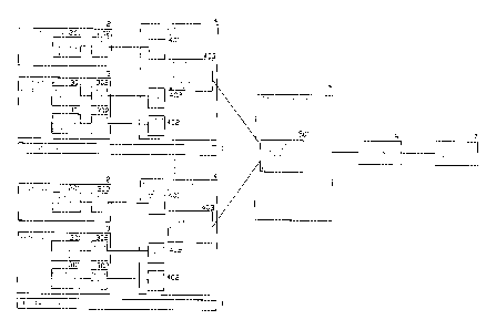
As shown in FIG. 1, the armed combat interactive system based on high
frequency
wireless scoring comprises:
a moving device 1 to carry a combat participant to move on a preset sports
field;
a combat device 2 for the combat participant on the moving device to hold, the
combat
device 2 is disposed with a first conductive part 201 to realize electrical
contact and a first port
202 to realize electric connect, the first conductive part 201 is connected to
the first port 202;
a protecting device 3 to protect the given external portion of the combat
participant on
the moving device, the protecting device is disposed with two second
conduction parts 301 to
realize electrical contact and two second ports 302 to realize electric
connect, the second
conductive part 301 is correspondingly connected to the second port 302;
a wireless identification control device 4, the wireless identification
control device 4
comprises a third port 401 and a fourth port 402 to realize an electric
connect and a first high
frequency wireless transmit module 403 to transmit wireless signal. The third
port 401 of the
wireless identification control device 4 is connected to the first port 202 of
the combat device
2, so that the wireless identification control device 4 is connected to the
first conductive part
201 of the combat device 2, the fourth port 402 of the wireless identification
control device 4
is connected to the second port 302 of the protecting device, so that the
wireless identification
control device 4 is connected to the second conductive part 301 of the
protecting device 3, and
a scoring disposing device, the scoring disposing device comprises a second
high
frequency wireless transmission module 501. The first high frequency wireless
transmission
module 403 is connected to the second high frequency wireless transmission
module 501 in
wireless communication way;
when the first conductive part 201 of the combat device one combat participant
holds
touches the second conductive part 301 of the protecting device of another
combat participant,
the wireless identification control device 4 of one combat participant sends a
high frequency
16
CA 02948925 2016-11-14
Attorney Ref. 1229P006CA01
pulse signal with ID identification code via the first conduction part 201.
The wireless
identification control device 4 of the other combat participant receives the
high frequency
pulse signal with ID identification code of the wireless identification
control device 4 of the
combat participant via the second conductive part 301, after corresponding
process, the
wireless identification control device 4 of the other combat participant sends
a scoring signal
to the scoring disposing device via the first high frequency wireless
transmission module, the
scoring disposing device recodes the score.
The scoring disposing device comprises a USB wireless main machine 5 disposed
around the sports field, a host computer 6 disposed around the sports field
and a LED display
screen 7 disposed around the sport field. The second high frequency wireless
transmission
module 501 is disposed in the USB wireless main machine 5, the USB wireless
main machine
5 and the wireless identification control device 4 exchange data in wireless
transmitting way
via the first high frequency wireless transmission module 403 and the second
high frequency
wireless transmission module 501. The host computer and the USB wireless main
machine
exchange data in wire transmitting way. The input of the LED display screen 7
is connected to
the output of the host computer 6.
As shown in FIG. 2, the wireless identification control device 4 further
comprises a
first MCU control module 404, a high frequency pulse contact transmission
module 405, an
alarm module and at least two high frequency pulse contact receiving module
406. Therein the
first high frequency wireless transmission module 403 is connected to the
first MCU control
module 404, the high frequency pulse signal output port of the first MCU
control module 404
is connected to the input of the high frequency pulse contact transmission
module 405, the
high frequency pulse signal input port of the first MCU control module 404 is
respectively
connected to the outputs of the at least two high frequency pulse contact
receiving module
406, the control signal output port of the first MCU control module 404 is
connected to the
alarm module, the output of the high frequency pulse contact transmission
module 405 is
connected to the third port 401, the inputs of the at least two high frequency
pulse contact
receiving module 406 are respectively connected to the corresponding fourth
port 402.
17
CA 02948925 2016-11-14
Attorney Ref. 1229P006CA01
In this embodiment, it is applied in fencing sports, the weapon is a sword,
the fencer
wears a helmet and an armor, the first conductive part 201 is disposed at the
sword, there are
two second conductive parts 301 disposed at the different positions of the
fencer holding the
weapon, one is disposed at the helmet, the other one is disposed at the armor,
the armor can
disposed with second conductive parts at different positions according to the
chest, the back,
the shoulder to score the stabled at the head and the body, so as to detailing
the scores.
Therefore, it needs corresponding high frequency pulse touch receiving module
406 and the
fourth ports 402. in this embodiment, the wireless identification control
device 4 comprises
two high frequency pulse touch receiving modules 406, one is connected to the
second
conductive part 301 of the helmet to receive the information of the head, the
other one is
connected to the second conductive part 301 of the armor to receive the
information of the
body, the number of the high frequency pulse touch receiving modules is
corresponding to the
second conductive parts, when the second conductive parts are divided into two
parts, it needs
two high frequency pulse touch receiving modules, when the second conductive
parts are
divided into four parts (one at the head, three at the body: the chest, the
back and the shoulder),
it needs four high frequency pulse touch receiving modules. The fourth ports
are disposed at
the same way.
In this embodiment, the alarm module comprises a LED indication module 408 and
a
music control module 407, other alarm devices are available. The LED
indication module 408
and the music control module 407 are respectively connected to the control
signal output port
of the first MCU control module 404.
As shown in FIG. 3 and FIG. 4, the USB wireless main machine 5 further
comprises
a second MCU control module 502 and a USB data transmission module 503,
therein, the
second high frequency wireless transmission module 501 is connected to the
second MCU
control module 502, the second MCU control module 502 is connected to the USB
data
transmission module 503. The USB wireless main machine 5 and the wireless
identification
control device 4 exchange data in wireless transmitting way via the first high
frequency
wireless transmission module 403 and the second high frequency wireless
transmission
18
CA 02948925 2016-11-14
Attorney Ref. 1229P006CA01
module 501. The host computer 6 is disposed with an ID encode module 601, a
signal
processing module 602, a scoring module 603 and a display module 604. The host
computer
6 and the USB wireless main machine 5 exchange data in wire transmitting way
via the USB
data transmission module 503.
The USB wireless main machine 5 further comprises an external wireless remote
transmission module 504 and a wireless remote receiving module 505, the output
of the
wireless remote receiving module 505 is connected to the second MCU control
module 502.
The ID encode module 601 of the host computer 6 gives the wireless
identification
control devices 4 different ID identification codes. When the first conduction
part 201 of a
first wireless identification control device 4 touches the second conduction
part 301 of a
second wireless identification control device 4, the first MCU control module
404 of the first
wireless identification control device sends a high frequency pulse signal
with ID
identification code of the wireless identification control device via the high
frequency pulse
touch transmission module 405 of the first wireless identification control
device. The high
frequency pulse touch receiving module 406 of the second wireless
identification control
device 4 receives the high frequency pulse signal with the corresponding ID
identification
code and transforms the high frequency pulse signal of the corresponding ID
identification
code to a corresponding ID identification code to the first MCU control module
404 of the
second wireless identification control device. The first MCU control module
404 of the
second wireless identification control device pack the corresponding ID
identification code,
the 1D identification code of the second wireless identification control code
and a feature code
identifying the position of the second conductive part 301 of the second
wireless identification
control device to a data packet to send to the USB wireless main machine 5 by
the
transmission protocol between the second wireless identification control
device and the USB
wireless main machine 5. The USB wireless main machine 5 sends the data packet
to the host
computer 6 via the USB data transmission module, the signal processing module
602 of the
host computer 6 identifies and processes the information of the data packet.
When the
corresponding ID identification code is the same as the preset ID
identification code, it is
19
CA 02948925 2016-11-14
Attorney Ref. 1229P006CA01
judged invalid signal. When the corresponding ID identification code is
different from the
present ID identification code, the signal processing module 602 of the host
computer 6
outputs control signal to the second wireless identification control device
via the USB
wireless main machine, the first MCU control module 404 of the second wireless
identification control device outputs signal to the alarm module of the second
wireless
identification control device after receiving the control signal, the alarm
module alarms, at the
same time, the signal processing module 602 of the host computer outputs
signal to the scoring
module 603 of the host computer, the scoring module 603 records the score
according to the
preset mode and outputs the scores to the display module 604 of the host
computer, the display
module 604 of the host computer drives the LED display screen to display.
The armed combat interactive system based on high frequency wireless scoring
records the score by high frequency pulse signal, the high frequency pulse
touch transmission
module 405 of the wireless identification control device 4 is used to read and
store the ED
identification code of the first MCU control module 404 and transform the ID
identification
code to high frequency pulse electric signal, when the first conductive part
201 of the combat
device 2 touches the second conductive part 301 of the protecting device 3,
the high frequency
pulse electric signal is sent out. The high frequency pulse touch receiving
module 406 of the
wireless identification control device 4 is used that, when the second
conductive part 301 of
the protecting device 3 touches the first conductive part 201 of the combat
device 2, it receives
the high frequency pulse electric signal sent by the high frequency pulse
touch transmission
module 405 of the first conductive part 201 of the combat device and restores
the high
frequency pulse electric signal to corresponding ID identification code and
sends to the first
MCU control module 404. The music control module 407 of the wireless
identification
control device 4 is used to receive the control command of the first MCU
control module 404
and drives the voice IC to play the sound, the voice is output by DAC and then
amplified by
special audio power amplifier to drive the speaker to make a sound. The LED
indication
module 408 of the wireless identification control device is used to receive
the control
command of the first MCU control module 404 and drive the LED to work, it is
configured to
two modes, one mode is that LED flashes 3s after an effective strike, the
other mode is that the
CA 02948925 2016-11-14
Attorney Ref. 1229P006CA01
LED lights slowly if the battery voltage drops down to the lowest working
voltage to indicate
low battery that it needs to recharge. The first MCU control module 404 of the
wireless
identification control device 4 is used to receive and process the ID
identification code, control
to send the high frequency pulse signal, control to play the music, control
the LED to indicate
and control the first frequency wireless transmission module 403 to receive
and send data. The
first high frequency wireless transmission module 403 of the wireless
identification control
device is used to send the data of the first MCU control module 404 to the USB
wireless main
machine 5 in wireless way and send the data sent from the USB wireless main
machine 5 in
wireless way to the first MCU control module 404, it has failure
retransmission function and
auto answer function, the transmission mode is half duplex two-way
transmission, the
transmission speed is 2M/s. the second high frequency wireless transmission
module 501 of
the USB wireless main machine is used to decode and process the data from the
first high
frequency wireless transmission module 403 and transmit to the second MCU
control module
502, it also used to analyze and process the data from the second MCU control
module 502
and send the data to the wireless identification control device 4. The second
MCU control
module 502 of the USB wireless main machine is used to receive the data of the
second high
frequency wireless transmission module 501 and analyze and pre-process the
data according
to the communication protocols, and send the data to the host computer 6, and
at the same time
receive and analyze the data of the host computer 6 and then send the result
to the second high
frequency transmission module 501, and at the same time real time read the
data of the
wireless remote receiving module 505 and send the processed key information to
the host
computer.
As shown in FIG. 5, the scoring process of the armed combat interactive system
comprises:
A. When the first conductive part 201 of the combat device 2 of a first
wireless
identification control device touches the second conductive part 301 of the
protecting device
3 of a second wireless identification control device, the high frequency pulse
touch receiving
module 406 of the second wireless identification control device receives the
high frequency
21
CA 02948925 2016-11-14
Attorney Ref. 1229P006CA01
pulse electric signal with ID identification code;
B. The high frequency pulse touch receiving module 406 sends the high
frequency
pulse electric signal with ID identification code to the first MCU control
module 404 of the
second wireless identification control device;
C. The first MCU control module 404 of the second wireless identification
control
device packs the 1D identification code, the self ID identification code and a
feature code
identifying the position of the second conductive part to a data packet to
send to the second
high frequency wireless transmission module 501 of the USB wireless main
machine 5 via the
first high frequency wireless transmission module 403;
D. The second high frequency wireless transmission module 501 of the USB
wireless
main machine sends the data packet to the second MCU control module of the USB
wireless
main machine, the second MCU control module 502 sends the processed data to
the host
computer 6 via the USB data transmission module 503;
E. The host computer 6 judges the validity of the data, if the data is
invalid, return to
step A; if the data is valid, continue to the next step;
F. The host machine 6 accumulates the scores according to the preset scoring
modes
and the corresponding positions of the second conductive parts 301 and
displays the results via
the LED display screen 7, at the same time, the host computer 6 transmits
control command to
the second MCU control module 502 of the USB wireless main machine 5 via the
USB data
transmission module 503;
G. The second MCU control module 502 of the USB wireless main machine 5 sends
the control command from the host machine 6 to the first high frequency
wireless transmission
module 403 of the second wireless identification control device 4 in wireless
way via the
second high frequency wireless transmission module 501;
H. The first high frequency wireless transmission module 403 of the second
wireless
identification control device transmits the control command to the first MCU
control module
22
CA 02948925 2016-11-14
Attorney Ref. 1229P006CA01
404, the first MCU control module 404 analyzes and processes to produce a
corresponding
control signal to output to the alarm module. The alarm module alarms with
sound and light,
then the end.
The armed combat interactive system based on high frequency wireless scoring
of the
present invention can achieve a two-player combat, A and B, they are riding on
corresponding
moving devices 1, A and B are respectively holding a combat device 2, for
example a sword,
A and B are respectively wearing a protecting device 3, for example an armor,
they are
respectively configured with a wireless identification control device 4, when
the first
conductive part 201 of the combat device 2 of A touches any second conductive
part 301, it
sends a high frequency pulse signal with an ID identification code of A out,
there can be two
situations, one is that A stables B, like the head, the other one is that A
stables himself, like the
head, when A stables B, the high frequency pulse touch receiving module 406 of
the wireless
identification control device 4 of B receives a high frequency pulse signal
with A's ID
identification code, B's wireless identification control device 4 processes
the signal and sends
the signal to the host computer 6 via the USB wireless main machine 5, the
signal processing
module 602 of the host computer 6 compares A's ID identification code and a
preset ID
identification code, as it is B's wireless identification control device 4
sends the signal, the
preset ID identification code is B's ID identification code, they are
different, so that the system
scores; if it's A stabled himself, the high frequency pulse touch receiving
module 406 of A's
wireless identification control device 4 also receives the high frequency
pulse signal with A's
ID identification code, A's wireless identification control device 4 processes
the signal and
sends the signal to the host computer via the USB wireless main machine 5, the
signal
processing module 602 of the host computer 6 compares A's ID identification
code and the
preset ID identification code, as it's A's wireless identification control
device 4 transmission
the signal, the preset ID identification code is A's ED identification code,
they are one code, it
is judged to an invalid signal, the system doesn't score.
The armed combat interactive system based on high frequency wireless scoring
of the
present invention can achieve multi-player, A, B, C, D four players fight, the
transmission
23
CA 02948925 2016-11-14
Attorney Ref. 1229P006CA01
process of scoring the signal is the same as above mentioned two-player mode,
the judge mode
of the host computer 6 is the same, it is judged to a valid signal if other
players stable, it is an
invalid signal if it's a self stable, in the scoring, it needs to score to the
stabling players
respectively.
The armed combat interactive system based on high frequency wireless scoring
of the
present invention can achieve group-player, the players are divided to two
groups, the first
group comprises A, B, C, the second group comprises D, E, F, the invalid
signal not only
comprises a self stabling, but also a group stabling, only if it's a opponent
group stabling, it is
valid, the preset ID identification code comprises the self ID identification
code and the group
ID identification code. The method is similar if there is multi-group and
multi-player.
As shown in FIGs 6-9, the armed combat interactive system based on high
frequency
wireless scoring of the present invention is provided that, the combat device
2 is a sword, the
combat device 2 comprises a sword body 21 and a sword handle 22. The sword
body 21
comprises a main backbone 211, an puncture-proof layer 212, a cushion layer
213 and a
surface layer 214; in this embodiment, the surface layer 214 is made of
conductive cloth, other
conductive material or composite conductive material are available, only if
they can catch the
signals, the surface layer 214 forms the first conductive part. The puncture-
proof layer 212
coats the main backbone 211, the buffer layer 213 coats the puncture-proof
layer 212, the
surface layer 214 coats the buffer layer 213. The sword body 21 is connected
to the sword
handle 22, the surface layer 214 is connected to the sword handle 22 by the
wire 2141. in other
case, the puncture-proof layer cannot be required.
The sword handle 22 comprises a backbone core 221, a sword fixing element 222,
a
handle 223, a sword hand guard 224 and a weight balance body 225, the sword
fixing element
222 is connected between the main backbone 211 of the sword and the backbone
core 221 of
the sword handle, one end of the handle element 223 is connected to the sword
fixing element
222, the other end of the handle element is connected to the weight balance
body 225. The
hand guard 224 is arc shaped connected between the sword fixing element 222
and the weight
balance body 225.
24
CA 02948925 2016-11-14
Attorney Ref. 1229P006CA01
The backbone core 221 of the sword handle and the main backbone of the sword
body
are integrally connected, that is to say, the backbone core 221 passes through
the sword fixing
element 222 to connect to the main backbone of the sword body, the backbone
core 221 of the
sword handle and the main backbone 211 of the sword body are the same
structure.
The handle 223 is conductive material body, the surface layer 214 is connected
to the
handle 223 by the wire 2141, the handle 223 forms the first port.
The main backbone 211 is an elastic structure made of elastic steel, so that
it can be
bended, in other case, the main backbone can be an elastic structure made of
other metal
elastic material or non-metal elastic material, or the compositing, for
example, it can be an
elastic structure body made of glass fibre or elastic plastic.
The puncture-proof 212 is a shell made of puncture-proof cloth or composite
material.
The buffer layer 213 is an elastic body made of composite material or rubber,
or
expanded plastic.
The cross section of the main backbone 211 is circle.
The cross section of the sword body 21 is barbell shaped, as shown in FIG. 9.
The external surface of the sword body of the present invention is disposed
with a
conductive cloth, so that the whole sword body is conductive, it is convenient
to catch the
signal so as to effectively score, it improves the entertainment of the
fencing. The sword body
comprises a main backbone 211, a puncture-proof layer 212, a buffer layer 213
and a
conductive cloth 214, it makes the sword body 21 with light weight, and it can
efficiently
fence, it is convenient for the game, also it lengthens the service life of
the sword, the main
backbone 211 of the combat device is made of elastic steel or glass fibre, it
is rigid and elastic.
The anti-puncturing layer is made of anti-puncturing cloth, it can reduce the
weight and the
size, it also is convenient to assemble. The buffer layer 213 is made of
sponge or rubber, it is
light in weight, it can also protect the main backbone, when touching the
opponent, it can
work with cushion function that it would not hurt the opponent.
CA 02948925 2016-11-14
Attorney Ref. 1229P006CA01
As shown in FIG. 10 and FIG. 11, the armed combat interactive system based on
high
frequency wireless scoring is provided that the combat device 2 can be another
structure, the
handle 223 can be an insulation body, the sword fixing element 222 is disposed
with a first
signal transmission port 2221, the conductive cloth 214 is connected to the
first signal
transmission port 2221 by the wire 2141. The first signal transmission port
forms the first port.
As shown in FIGs 12-16, the armed combat interactive system based on high
frequency wireless scoring is provided that, the protecting device 3 comprises
an armor 31.
The armor 31 comprises a protecting cloth inner layer 311 and a conductive
material outer
layer 312, the conductive material outer layer 312 covers the center upper
portion of the
conductive material outer layer forms the second conductive part. The armor 31
is disposed
with a first slot at the position corresponding to the front portion of the
human being wearing
the armor, the first slot is disposed with a first zipper 313 (the front
zipper) to close the first
slot when the first zipper 313 is zipped. The first zipper 313 is unzipped for
the user to wear
the armor, the armor is further disposed with a signal joint 314 at the
position of the end of the
arm of the human being for the electric signal of the handle combat weapon,
the protecting
armor of this embodiment is the protecting device for fending sports, the
signal joint 314 is
used for the electric signal of the handle composite conductive sword. The
armor 31 is further
disposed with a signal transmission joint 315, which is disposed with at least
two signal
transmission wires, one wire is connected to the electric signal joint of the
combat weapon, the
conductive word, the other wire is the second port to connect to the
conductive cloth 3121 of
the armor.
The armor 31 is disposed with an air inlet joint 316 at the position
corresponding to the
portion of the human being below the wrest, an air pipe 3161 at the inner side
surrounding the
wrest corresponding to the inner side of the wrest of the human being, the air
pipe 3161 is
connected to the air inlet joint 316, the air pipe 3161 is disposed with a
plurality of air spraying
holes directed upwardly. The armor 31 is further disposed with a plurality of
first air holes
3162 at the position corresponding to the front chest of the human being.
The protecting device 3 further comprises a helmet 32. The helmet 32 comprises
a
26
CA 02948925 2016-11-14
Attorney Ref. 1229P006CA01
shell shaped base body 321 made of glass steel and a conductive layer 322
coated on the
surface of the base body. The signal transmission joint 315 of the helmet 1 is
further disposed
with a third signal transmission wire, which is connected to the conductive
layer 322 of the
helmet. The upper portion of the armor 31 is disposed with a helmet joint
3151, the third signal
transmission wire is connected to the conductive layer 322 of the helmet joint
3151. The
helmet can be made of metal material, the third signal transmission wire forms
the second port
connected to the metal material of the helmet.
The protecting device 3 further comprises an air blowing device 351, which is
connected to the air inlet joint 316.
The helmet 32 is disposed with a metal protecting screen 323 corresponding the
face
of the human being.
The protecting device 3 further comprises a neck collar 33 connected between
the
helmet 32 and the armor 31, the neck collar 33 comprises three parts: an upper
part 331, a
center part and a lower part 333. The upper and lower parts are made of
material composed of
tabby cloth material and hard elastic material body, therein, the tabby cloth
is disposed at the
surface layer. The center part 332 is applied with elastic cloth. The elastic
cloth 332 is
connected between the upper tabby cloth and the lower tabby cloth.
The lower portion 333 of the neck collar is disposed with a plurality of
second air holes
3331 surrounding the neck of the human being.
The neck collar 33 is disposed with a disconnecting portion along the vertical
direction
to vertically disconnect neck collar. The disconnecting portion is disposed
with a first nylon
fastener 341, the neck collar 33 forms a shape surrounding a neck of a human
being by the first
nylon fastener 341, the first nylon fastener can be changed by a button.
The neck collar 33 is connected and fixed to the helmet 2 by the second nylon
fastener
342, the second nylon fastener 342 can be changed by a button.
The neck collar 33 is connected to the armor 31 by the second zipper 343.
27
CA 02948925 2016-11-14
Attorney Ref. 1229P006CA01
The surface of the armor 31 is made of conductive cloth 312, so that it can
transmit
signals. The armor 31 is disposed with an air inlet joint 316 at the position
corresponding to
the portion of the human being below the wrest, an air pipe 3161 at the inner
side surrounding
the wrest corresponding to the inner side of the wrest of the human being, the
air pipe 3161 is
connected to the air inlet joint 316, the air pipe 3161 is disposed with a
plurality of air spraying
holes directed upwardly. The armor 31 is further disposed with a plurality of
first air holes
3162 at the position corresponding to the front chest of the human being. The
present
invention is provided with the air inlet joint 316 connected to an air blowing
device to blow
hot air or cool air along the wrest and the air flows out of the first air
holes 3162, so that it can
achieve ventilation at the inner side, it works with the sweat layer the human
being wearing
(wearing under the armor) for heat proofing and deodorization.
The present invention is provided with a protecting armor that can
transmission signals
and regulate temperature, the armor is disposed with a first zipper 313 at the
front position
corresponding to a human being, it is convenient to wear; a second zipper 343
is disposed
between the neck collar and the armor to make the neck collar detachable for
washing and
cleaning. The surface of the upper and lower portion of the neck collar is
made of cloth, the
inner layer is applied with an elastic material with a certain hardness (for
bending), the center
portion is made of elastic cloth, so that the player feels comfort when
nodding or turning
around the head. The outer side is connected by nylon fastener 341, the player
can adjust the
size of the neck collar according to self condition. The second air holes 3331
of the neck collar
have breath and heat proofing functions. The neck collar 33 is connected to
the armor 31 by
the second zipper 343 and is connected to the helmet 32 by nylon fastener 342,
it works with
protecting the neck and the throat function.
The present invention is provided with a protecting armor that can
transmission signals
and regulate temperature, the helmet is applied with a safety helmet, it is
made of a glass steel
base body, and embedded with a head cloth, a jaw belt and other safety
accessories, it is coated
with conducting paint or electroplated, a metal protecting screen 323 is
further assembled to
transmit signal and protect the head. The nylon fastener 342 is used to
connect to the neck
28
CA 02948925 2016-11-14
Attorney Ref. 1229P006CA01
collar 33.
As shown in FIGs. 17-25, the armed combat interactive system based on high
frequency wireless scoring of the present invention is provided that, the
moving device 1 is a
motor driven horse riding machine, the motor driven horse riding machine 1
comprises a
bottom plate 11, a walking mechanism 12, a driving mechanism 13, a moving
mechanism 14,
a stand 15, a steering mechanism 17 and an animal model 16. The waling
mechanism 12 is
assembled to the bottom plate 11 to drive the bottom plate 11 to walk. The
driving mechanism
13 is assembled to the bottom plate 11 and is coupled to the walking mechanism
12. The stand
is assembled to the bottom plate 11, the moving mechanism 14 is assembled to
the stand
10 14 and is coupled to the driving mechanism 13, the moving mechanism 14
imitates an animal
under the supporting of the stand 15 and the driving of the driving mechanism
13. The animal
model 16is assembled to the moving mechanism 14 to form a movable animal. The
steering
mechanism 7 is assembled to the front portion of the animal model 16 and is
coupled to the
walking mechanism 12 to control the steering of the walking mechanism 12.
15 The riding machine further comprises a transmission mechanism 18,
the transmission
mechanism 18 is assembled to the bottom plate 11, the driving mechanism 13 is
respectively
coupled to the walking mechanism 12 and the moving mechanism 14 via the
transmission
mechanism 18.
The transmission 18 comprises a first transmission 181 with single speed and a
second
transmission 182 with multi-speed, the driving mechanism 13 is coupled to the
walking
mechanism 12 via the first transmission 181 with single speed, the first
transmission 181
comprises a first driving wheel 181 and a first driven wheel 181b, the output
of the driving
mechanism 13 is connected to the first driving wheel 181a, the first driving
wheel 181a
transmits the power to the first driven wheel 181b via the chain, the first
driven wheel 181b is
connected to the rear wheel of the bottom plate 11 to drive the riding machine
to move
forwardly or backwardly. The second transmission mechanism 182 comprises a
second
driving wheel 182a, a second driven wheel 182b, a reducer 182c and a
transmission belt wheel
182d. The output of the driving mechanism 13 is connected to the second
driving wheel 182a,
29
CA 02948925 2016-11-14
Attorney Ref. 1229P006CA01
the second driving wheel 182a transmits power to the second driven wheel 182b
via the chain,
and is connected to the input of the reducer 182c, the output of the reducer
182c outputs via the
transmission belt wheel 182d, and is connected to the driving shaft of the
moving mechanism
14 to drive the driving shaft to rotate.
The moving mechanism 14 comprises a swinging cross arm 141 and a simulating
motion mechanism 142. The simulating motion mechanism 142 comprises two cranks
142a,
two driven rotating arms 142b, a driving shaft 142c and a driven shaft 142d.
The front portion
of the stand 15 is disposed with a driving bearing base 151, the driving shaft
142c is assembled
to the driving bearing base, the rear portion of the stand 15 is disposed with
a driven bearing
base 152, the driven shaft 142d is assembled to the driven bearing base 152.
The driving shaft
142c is coupled to the driving mechanism 13; each end of the two cranks 142a
are respectively
connected to the two ends of the driving shaft 142c; each other end of the two
cranks 142a are
respectively connected to the front portion of the swinging cross arm 141; two
driven rotating
arms 142b are respectively connected between the two ends of the driven shaft
142d and the
rear portion of the swinging cross arm141. The crank 142a rotates under the
driving of the
driving shaft 142c to drive the front portion of the swinging cross arm 141 to
rotate about the
driving shaft 142c, the driven rotating arm 142b swings forwardly and
backwardly under the
driving of the swinging cross arm 141.
The swinging cross arm 141 comprises a cross arm body 141a, a saddle shaped
support
141b and a step mounting rack 141c. The front portion of the cross arm body
141a is disposed
with a driving shaft 142c to connect to the crank 142a, the rear portion of
the cross arm body
141a is disposed with a driven shaft 142d to connect to the driven rotating
arm 142b. The
saddle shaped support 141b is fixed to the rear portion of the cross arm body
141a. The step
mounting rack 141c is fixed to the bottom portions of the cross arm body 141a.
The step
mounting rack 141c is disposed at two sides of the cross arm body in dividing
way and is
connected respectively with a left step and a right step. The left step is
disposed with a brake
device, the brake device is a disc brake assembled to the rear wheel rotating
shaft 121c, the
brake step is assembled to the left step. When the brake step is pressed, the
brake 121f works
CA 02948925 2016-11-14
Attorney Ref. 1229P006CA01
to brake. The right step is assembled with a accelerator, which is connected
to the controller,
the controller changes the output power of the driving mechanism 13 to realize
speed
regulating.
The animal model 16 comprises a fixing rack and an animal model shell. The
fixing
rack comprises a body fixing rack and a head fixing rack, the body fixing rack
is fixed to the
upper portion of the cross arm body 141a, the head fixing rack is fixed to the
upper portion of
the front side of the body fixing rack. The steering mechanism 17 is assembled
to the head
fixing rack.
The steering mechanism 17 comprises a steering handle 171, a steering upper
chain
wheel 172, a steering lower chain wheel 173, an upper chain 174, a lower chain
175 and a steel
wire, the steering handle 171 is assembled to the head fixing rack, the
steering upper chain
wheel 172 is assembled to the steering handle 171, the steering lower chain
wheel 173 is
assembled to the walking mechanism 12, the upper chain and the lower chain are
respectively
assembled to the steering upper chain wheel and the steering lower chain
wheel, the center of
the two chains are connected by the steel wire. The steering handle 717 is
assembled with a
gear device with two gears, a forward gear and a backward gear. The gear
device is connected
to a controller, the controller is used to control the turn and reverse of the
motor to achieve
forward and backward moving state of the machine.
The walking mechanism 12 comprises a front wheel mechanism 122 and a rear
wheel
mechanism 121, the front wheel mechanism 122 comprises two front wheels 122a
and a front
wheel rotating shaft 122b, two front wheels 122a are respectively assembled to
two ends of the
front wheel rotating shaft 122b, the lower chain wheel 173 is assembled to the
upper end of the
front wheel rotating shaft. The front wheel mechanism 122 is rotatably
assembled to the front
shell fixing support 112 of the bottom plate 11.
The rear wheel mechanism 121 comprises a driving rear wheel 121a, a driven
rear
wheel 121b, a rear wheel rotating shaft 121c, a support bearing base 121d, a
chain plate 121e
and a brake 121f. The driving rear wheel 121a, the driven rear wheel 121b, the
support bearing
31
CA 02948925 2016-11-14
Attorney Ref. 1229P006CAO I
base 121d, the chain plate 121e and the brake 121f are respectively assembled
to the rear
wheel rotating shaft 121c. The driving rear wheel 121a is assembled to the
rear wheel rotating
shaft 121c by a expanding sleeve, the driving rear wheel 121a and the rear
wheel rotating shaft
121c rotate synchronously. The driven rear wheel 121b is assembled to the rear
wheel rotating
shaft 121c by an antifriction bearing. The rear wheel mechanism 121 is
assembled to the
bottom plate 11 by the support bearing base 121d connecting to the bottom
plate 11. The
driving rear wheel 121 and the driven rear wheel 121b are respectively
assembled to the rear
wheel fixing base 111 of the bottom plate 11.
The moving device 1 further comprises an energy storing mechanism, the energy
storing mechanism comprises a first spring mechanism 191 and a second spring
mechanism
192, the first spring mechanism 191 is assembled between the swinging cross
arm 141 and the
bottom plate 11. The second spring mechanism 192 is assembled between the
stand 15 and the
driven rotating arm 152b. The first spring mechanism 191 and the second spring
mechanism
192 use the springs to store energy and release energy, when the moving
mechanism 14 swings
downwardly, it stores energy, when the moving mechanism 14 swings upwardly, it
releases
energy, it can achieve energy saving effect.
The moving mechanism further comprises a ground conductive wheel 193, the
ground
conductive wheel 193 is assembled to the bottom portion of the bottom plate
11. the
conductive wheel 193 is assembled to the bottom portion of the bottom plate by
a bearing
base, when the machine moves the conductive wheel rolls with the rear wheel on
the
conductive ground to form a stable and uninterruptable connection to realize a
common
reference ground point with other riding machines.
The moving device 1 further comprises a temperature regulating device, the
temperature regulating device comprise an air pump 194 and an air pipe195, the
air pump is
assembled to the stand, the air pipe is extending from the air pipe and fixing
to the saddle
shaped support. The air pump regulates the temperature produce air flow, and
sprays the air
flow from the air pipe to the rider to regulate the temperature.
32
CA 02948925 2016-11-14
Attorney Ref. 1229P006CA01
The external edge of the bottom plate 11 is disposed with anti-collision
device, which
is made of tire and inner tube with special shape. When collision happens, the
tire absorbs the
energy to achieve buffer effect.
The armed combat interactive system based on high frequency wireless scoring
of the
present invention is applied with a motor-driven riding entertainment and
fitness machine to
be the moving device, the power source of the moving device is a DC motor, it
can use a
battery set and controller to supply power to the motor and control the motor.
The motor
output power transmits to the rear wheel mechanism via the transmission
mechanism and the
imitating moving mechanism. The animal model is assembled with a main switch,
the riding
machine is switched on to work. The rider rides on the saddle and holds the
steering handle,
the feet place on the steps. The right step is assembled with a accelerator.
When the accelerator
signal is transmitted to the controller, the controller controls the motor to
rotate, the motor
drives the rear wheel shaft to rotate by the reducing mechanism, the rear
wheel shaft drives the
driving rear wheel to rotate so as to drive the whole machine to move forward
and backward.
At the same time, the motor drives the imitating mechanism to move by the
multi-speed
transmission mechanism, the imitating mechanism drives the animal model and
the swinging
cross arm to move and also drives the saddle to imitate the movement path of
the center of a
horse. The accelerator can achieve starting up the whole machine to move and
controlling the
moving speed of the whole machine. The left step is assembled with a brake,
when the brake
signal is transmitted to the controller, the controller controls the motor to
stop working, with
the brake, the rear wheel shaft stops rotating, the driving rear wheel stops
rotating, the whole
machine is braked. The rider can control the steering handle, which is coupled
to the steering
device, to control the riding machine to move in any direction. The driving
rear wheel and the
driven rear wheel do not rotate synchronously when turning over, it avoids
wheelslip. The
steering handle is assembled with a gear device with two gears, a forward gear
and a backward
gear. When in the forward gear, the riding machine moves forwardly. When in
backward gear,
the riding machine moves backwardly. The external edge of the bottom plate is
disposed with
collision-proof tire, the tire absorbs the energy of collision to achieve
buffer effect, so as to
protect the rider. During the riding, the temperature regulating device
provides air flow with
33
CA 02948925 2016-11-14
Attorney Ref. 1229P006CA01
different temperature to the rider so as to adjust the circumjacent
temperature of the rider to
achieve comfort. When riding, the rider controls the machine to move
forwardly, backwardly
and turning round as his pleases, and he can also chase and crash other
riders, it can obtain
fitness and entertainment, it also can achieve relax and emotional exchange
that it gives a new
using experiment for the users.
Industrial Applicability
The present invention is provided with an armed combat interactive system
based on
high frequency wireless scoring, which comprises a moving device, a combat
device, a
protecting device, a wireless identification control device and a scoring
device, the wireless
identification control device comprises a first MCU control module, a high
frequency pulse
touch transmission module, an alarm module, a high frequency pulse touch
receiving module
and a first high frequency wireless transmission module, the scoring disposing
device
comprises a USB wireless host machine disposed around the sports field, a host
computer
disposed around the sports field and a LED display screen disposed around the
sport field. The
USB wireless host machine further comprises a second MCU control module, a USB
data
transmission module and a first high frequency wireless transmission module,
the combat
comprises a device body and a device handle. The device body comprises a main
backbone, a
cushion layer and a surface layer from the inside to the outside. The surface
layer is
conductive, the protecting device comprises an armor, a helmet and a neck
collar, the moving
device comprises a bottom plate, a walking mechanism, a driving mechanism, a
moving
mechanism, a stand, a steering mechanism and an animal model, it is convenient
for industrial
manufacturing, the moving device, the combat device, the protecting device,
the wireless
identification control device and the scoring device are also convenient for
industrial
manufacturing.
Although the present invention has been described with reference to the
preferred
embodiments thereof for carrying out the patent for invention, it is apparent
to those skilled in
the art that a variety of modifications and changes may be made without
departing from the
scope of the patent for invention which is intended to be defined by the
appended claims.
34