Note : Les descriptions sont présentées dans la langue officielle dans laquelle elles ont été soumises.
CA 02949742 2016-11-28
WIND-RESISTANT SUN-PROOF BLIND
BACKGROUND OF THE INVENTION
Field of Invention
The present invention relates to a blind, particularly to a wind-resistant sun-
proof
blind in the field of mechanical technology.
Related Art
People are used to pulling the blind down to shield off sunshine in hot
summers.
However, the wind blown into the room through windows will swing the blind
back
and forth. In such a case, not only a poor sun-proof effect of the blind is
produced,
but also noises will be generated by the blind that wings back and forth.
Particularly
rest and study of students as well as relaxation of patients will be adversely
impacted
as such in locations like schools and hospitals.
To this end, someone invented a wind-resistant sun-proof blind. At present the
outdoor wind-resistant sun-proof blind employs a wire rope to prevent moving,
but
the wire rope could only fix the lower end of curtain cloth. When the wind
power is
strong, the blind tends to be blown up as a hole, producing a poor wind-
resistant
effect. Another wind-resistant blind, such as that is disclosed in Chinese
patent
CN201519032U, is connected with several post-like weights at equal distances
at its
bottom. A hook is provided at the bottom of the weight, and a protective cover
is
located on the threads on the surface of the post-like weights. Even though
this blind
could address problems with ordinary blinds, like poor stability and easy blow-
up by
wind, the structure of the blind is complicated and the wind-resistant effect
can only
be achieved if the blind is completely laid down, which cannot exhibit
multiple
functions. Nylon zippers are provided on both sides of the curtain cloth in
some
blinds. In such blinds with nylon zippers, the thickness of the curtain cloth
is
different from that of nylon zippers, and there is displacement when the
curtain cloth
1
CA 02949742 2016-11-28
is wound. A power-saving wind-resistant blind dedicated to classrooms, is
disclosed
in Chinese Patent CN200964780Y. Both ends of the blind are disposed in two
symmetric upper holders. An upper ratchet wheel is provided at one end of the
upper roller for driving the upper roller to rotate. An annular ratchet wheel
zipper is
covered on the upper ratchet wheel. An annular connection bar covered on both
ends of the upper and lower rollers is located between the upper roller and
lower
roller. The connection bar is tightened between the upper roller and the lower
roller.
A central roller is positioned between two central holders for winding the sun-
proof
spoke. The lower end of the sun-proof spoke is fixed on the annular connection
bars
on both sides via a crossbar. Even though the blind is effectively wind-
resistant, it
has a complicated structure, is difficult to operate, has to be operated
purely by
manpower, and cannot be easily mounted.
SUMMARY OF THE INVENTION
In order to address the aforesaid defects, the present invention provides a
wind-resistant sun-proof blind which has a firm and reliable structure, a good
guide
nature and strong wind resistance.
It is therefore an object of the present invention to provide a wind-resistant
sun-proof blind, comprising a curtain cloth, a window cover and a reel pipe
assembly
rotably mounted within the window cover, in which the curtain cloth is wound
outside
of the reel pipe assembly, the reel pipe assembly turns to drive the curtain
cloth to roll
out or in, each of both ends of the window cover has a downward lateral rail
fixedly
connected therewith, and the side of the lateral rail facing to the curtain
cloth has a
longitudinal opening. Two symmetrically disposed lock bars are mounted within
the
lateral rail along the longitudinal direction, and a gap facing to one side of
the curtain
cloth is formed between the said two lock bars, and the upper opening of the
gap is in
communication with the window cover. Two lateral edges of the curtain cloth
extend into the inner cavity of the lateral rail and are transversely fixedly
connected
2
CA 02949742 2016-11-28
with a flexible positioning element after passing through the longitudinal
opening of
the lateral rail on the same side and the gap between the said two lock bars
respectively. The reel pipe assembly has two symmetrically disposed annular
grooves and when the curtain cloth is wound around the reel pipe, both lateral
edges
of the curtain cloth are wound at the corresponding annular grooves
respectively, and
the outer diameter of the positioning element is larger than the width of the
gap
between the two lock bars;
In the wind-resistant sun-proof blind of the invention, two said window covers
are provided including a first window cover and a second window cover; two
said
curtain cloths are provided including a first telescopic curtain cloth and a
second
telescopic curtain cloth; the first window cover is mounted at the upper
portion of the
first window frame, the first window frame has a first window and the first
telescopic
curtain cloth is provided within the first window cover;
the second window frame is fixedly connected with one side of the first window
frame and has a second window, the second window is corresponding to the
position
of the first window, the second window cover is mounted at the upper portion
of the
second window frame, and the second telescopic curtain cloth is provided
within the
second window cover; or, a lateral seal is fixedly connected with one side of
the first
window frame and has a second window, and the second window is corresponding
to
the position of the first window.
In the wind-resistant sun-proof blind of the invention, the reel pipe assembly
includes a reel pipe and an active wheel plug and a passive wheel plug
inserted and
fixed into both ends of the reel pipe, the annular grooves are opened on the
portions of
the active wheel plug and passive wheel plug exposed out of the reel pipe
respectively,
and the outer diameter of the annular grooves is smaller than the diameter of
the reel
pipe and the width of the curtain cloth is larger than the length of the reel
pipe.
In the wind-resistant sun-proof blind of the invention, the length of the
positioning element is identical to that of the curtain cloth and the
positioning element
3
CA 02949742 2016-11-28
is fixedly connected with the lateral edge of the curtain cloth by sewing.
In the wind-resistant sun-proof blind of the invention, each of both lateral
edges
of the curtain cloth is fixedly connected with a skirt, and the curtain cloth
is
transversely fixedly connected with the positioning element through the
skirts.
In the wind-resistant sun-proof blind of the invention, a rocker gear case
having a
hang ring is connected with the outer end of the active wheel plug and a
vertically
disposed rocker is hung onto the hang ring.
In the wind-resistant sun-proof blind of the invention, the positioning
element is a
bead chain, a soft traction steel wire or a nylon rope.
In the wind-resistant sun-proof blind of the invention, symmetrical support
parts
and guide parts are disposed on both sides of the first window frame, the
support part
and the guide part on the same side are integrated with each other, the upper
end of
the support part is higher than that of the guide part, that is to say, a gap
is formed
above the support part and guide part on the same side; and the first window
cover is
mounted at the gaps on both sides of the first window frame.
In the wind-resistant sun-proof blind of the invention, an upper slide is
connected
with the upper end of the support parts on both sides, a lower slide is
connected with
the lower end of the support parts on both sides, and the upper slide is
corresponding
to the lower slide.
In the wind-resistant sun-proof blind of the invention, the lateral seal is
formed by
vertical seals on both sides, the upper slide connected with the upper end of
the seals
on both sides and the lower slide connected with the lower end of the seals on
both
sides, in which the upper slide is corresponding to the lower slide.
In the wind-resistant sun-proof blind of the invention, a first slot is opened
on one
side of the support part along the longitudinal direction, and a second slot
is opened
on one side of the lateral seal along the longitudinal direction
correspondingly; and
two lateral edges of a plastic strip are inserted and fixed into the first
slot and the
second slot on the same side respectively.
4
CA 02949742 2016-11-28
In the wind-resistant sun-proof blind of the invention, a lateral seal
limiting part
is provided on the inner side of the seal on one side for positioning the
sliding window,
and a window body limiting part is provided on the inner side of the first
window
frame support part on the opposite side.
In the wind-resistant sun-proof blind of the invention, symmetric support
parts
and guide parts are disposed on both sides of the second window frame, the
support
part and the guide part on the same side are integrated with each other, the
upper end
of the support part is higher than that of the guide part, that is to say, a
gap is formed
above the support part and guide part on the same side; and the second window
cover
= is mounted at the gaps on both sides of the second window frame.
In the wind-resistant sun-proof blind of the invention, the bead chain is made
from several plastic beads fixedly connected to one nylon rope and spaced from
each
other, the distance between adjacent beads is 12-20 mm, and the diameter of
the beads
is 2.5-4 mm.
In the wind-resistant sun-proof blind of the invention, the length of the
annular
grooves is 15-40 mm and the depth thereof is 2-6 mm.
The wind-resistant sun-proof blind of the invention has the following
advantages
over the prior art:
Firstly, a flexible positioning element is fixedly connected with both lateral
edges
of the curtain cloth by sewing. The positioning element moves along with the
curtain cloth, to makes sure the positioning element will not be fixed to
press against
the skirts of the curtain cloth when the curtain cloth moves up and down under
extremely strong wind, and the curtain cloth will not move up and down
unsmoothly.
Meanwhile, the positioning element is fixedly connected with the skirts by
sewing in
such a manner that the positioning element could move up and down as the
curtain
cloth moves up and down. In other words, the positioning element moves along
with
the curtain cloth. As such, the positioning element will not be broken by too
strong
wind and the curtain cloth will not be damaged by the facture of the broken
CA 02949742 2016-11-28
positioning element as the positioning element fixedly mounted within the
lateral rails
does not move synchronously with the curtain cloth.
Secondly, a steel wire wheel having a scroll spring is mounted on the
bulkhead.
A traction steel wire is wound around the steel wire wheel and has one end
wound
onto the steel wire wheel and the other end passing through the roller and
fixedly
connected with the lower rod. When the curtain cloth moves up, the traction
steel
wire tightens the scroll spring, and when the curtain cloth moves down, the
curtain
cloth is driven by elastic force of the scroll spring to move down.
Consequently, the
curtain cloth could smoothly move down even under wind pressures.
BRIEF DESCRIPTION OF THE DRAWINGS
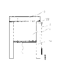
FIG. 1 is a diagram of the structure of the first embodiment;
FIG. 2 is an exploded diagram of the structure of the first embodiment;
FIG. 3 is a vertical section view of the first embodiment;
FIG. 4 is an enlarged diagram of the part A of fig. 3;
FIG. 5 is transverse partial section view of the first embodiment;
FIG. 6 is a diagram of the structure of the second embodiment;
FIG. 7 is an exploded diagram of the structure of the second embodiment;
FIG. 8 is an exploded diagram of the structure of the front window cover of
the
second embodiment;
FIG. 9 is a stereogram of the structure of the sun-proof component of the
second
embodiment;
FIG. 10 is a longitudinal section view of the part a of fig. 9;
FIG. 11 is a diagram of the structure of the bead chain;
6
CA 02949742 2016-11-28
FIG. 12 is an exploded view of the sun-proof component of the second
embodiment;
FIG. 13 is a partial longitudinal section view of the sun-proof component of
the
second embodiment;
FIG. 14 is an exploded diagram of the structure of the window frame of the
second embodiment;
FIG. 15 is an exploded diagram of the structure of the back window cover of
the
second embodiment;
FIG. 16 is a front view of the second embodiment;
FIG. 17 is an A-A section view of fig. 16;
FIG. 18 is enlarged diagram of the structure of the part B of fig. 17;
FIG. 19 is an exploded view of the structure of the indoor and outdoor window
frame having a sliding window;
FIG. 20 is an exploded view of the part M of fig. 19 (outdoor window frame,
i.e.,
front window frame); and
FIG. 21 is an exploded view of the part N of fig. 19 (indoor window frame,
i.e.,
back window frame).
DETAILED DESCRIPTION OF THE INVENTION
Embodiments of the present invention will be described in detail below with
reference to the drawings. However, the present invention shall not be limited
to
these embodiments.
First Embodiment
As shown in figs. 1-5, the wind-resistant sun-proof blind according to this
embodiment comprises curtain cloth 11, a window cover 12, a reel pipe assembly
7
CA 02949742 2016-11-28
mounted within the window cover 12, lateral rails 14 positioned on both sides
of the
curtain cloth 11, a lower rod 15 disposed at the lower end of the curtain
cloth 11, a
rocker 16 and so on. The reel pipe assembly is rotably mounted within the
window
cover 12. The curtain cloth 11 is wound outside of the reel pipe assembly. The
rotation of the reel pipe assembly drives the curtain cloth 11 to unwind and
wind.
An end cap 113 is provided at each end of the window cover and is inserted and
fixed
into the upper end of the lateral rail 14.
Each end of the window cover 12 is fixedly connected to the aforesaid lateral
rail
14. The lateral rails 14 have a longitudinal opening on their sides facing
toward the
curtain cloth 11. The lower end of the lateral rail 14 is fixedly connected
with a
bulkhead 111. The upper end of the lateral rail 14 is fixedly connected with a
guide
blank cap 112. The blank cap 112 could be used to pass through the edge of the
curtain cloth 11 longitudinally. The impurities like dust, could not enter the
lateral
rails thanks to the bulkheads 111 and guide blank caps 112, which further
guarantees
tidiness of rails within the lateral rails 14 and alleviates difficulty for
the curtain cloth
11 to move up and down because of jam of rails brought by too many impurities.
Two symmetrically disposed lock bars 114 are mounted into the lateral rail 14
along the longitudinal direction. A gap 115 is formed between two lock bars
114 to
face to one side of the curtain cloth 11. The upper end of the gap 115 is in
communication with the window cover 12. Two lateral edges of the curtain cloth
11
pass through the longitudinal opening of the lateral rail 14 on the same side
and the
gap 115 between the said two lock bars 114 respectively, and then extend into
the
inner cavity of the lateral rails 14 and are fixedly connected with flexible
positioning
elements 17 in a transverse direction. The positioning elements 17 move in an
axial
direction within the lateral rails 14 as the curtain cloth 11 moves up and
down. The
outer diameter of the positioning element 17 is larger than the width of gap
between
two lock bars 114, which ensures the positioning elements 17 will not be
disengaged
from the lateral rails 14.
A skirt ha is fixed to each lateral edge of the curtain cloth 11a. The curtain
8
CA 02949742 2016-11-28
cloth 11 passes through the skirts 11a and is fixedly connected with the
positioning
elements by transverse sewing. In this embodiment, the positioning element 17
is a
bead chain, and could also be a soft traction steel wire 119 or a nylon rope
or other
circular soft belt upon actual circumstances and demands of the users. The
length of
the positioning elements 17 is identical to that of the curtain cloth 11, so
that the
curtain cloth 11 is held by the positioning elements through the skirts ha and
is
always straightened when wind blows to the curtain cloth 11. This said, the
curtain
cloth 11 will not be easily swelled up. The positioning elements 17 will move
outward along with the curtain cloth 11 even when the curtain cloth 11 is
slighted
swelled up when wind is extremely strong, ensuring that the positioning
elements 17
will not be fixed against the skirts ha of the curtain cloth 11 and the
curtain cloth 11
will not move up and down unsmoothly when the curtain cloth 11 moves up and
down with extremely strong wind. Meanwhile, the positioning elements 17 are
fixed
to the skirts 11a by sewing, so that the positioning elements 17 will move up
and
down as the curtain cloth 11 moves up and down. In other words, the
positioning
elements 17 will move along with the curtain cloth 11. Accordingly, such an
accident will not happen, in which the positioning elements 17 are fixedly
mounted
within the lateral rails 14, do not move in synchronization with the curtain
cloth 11
and are broken by extremely strong wind, and the curtain cloth 11 is destroyed
by the
fracture of the broken positioning elements 17.
The skirts 11a could be made from cloth of ordinary nylon composite materials
or
ordinary chemical fiber materials, have good tensile resistance and are not
easy to be
broken. The skirt lla could be folded to form a circumferentially closed
space. As
such, the positioning elements 17 could be inserted into the pace and fixedly
connected with the skirts 11 a by sewing.
The curtain cloth 11 and skirts ha could be fixed to each other by hot sealing
under temperature of 150-400 C by using a hot sealing machine or by sewing by
using a sewing machine. Consequently, the curtain cloth 11 could be connected
with
the skirts ha in a firmer manner. When wind is strong, the positioning
elements 17
9
CA 02949742 2016-11-28
will hold the skirts ha and the skirts 11a and curtain cloth 11 will not be
readily torn
apart by wind, thus having good wind-resistance.
The reel pipe assembly includes a reel pipe 13 and an active wheel plug 18 and
a
passive wheel plug 19 inserted and fixed into both ends of the reel pipe 13.
The
width of the curtain cloth 11 is larger than length of the reel pipe. An
annular groove
110 is provided on each of the portions of the active wheel plug 18 and
passive wheel
plug 19 out of the reel pipe 13, and has an outer diameter small than the
diameter of
the reel pipe 13. When the curtain cloth 11 is wound onto the reel pipe 13,
both
lateral edges of the curtain cloth 11 are respectively wound at the
corresponding
annular grooves 110. In other words, when the curtain cloth 11 moves up and is
wound by the reel pipe 13, the positioning elements 17 are wound up and
located at
the corresponding annular grooves 110 as the curtain cloth 11 moves up. As the
positioning elements 17 are fixedly connected with the skirts 11a by sewing,
the
thickness generated by winding up the skirts 11a, i.e., the superimposed
thickness
formed by winding up the positioning elements 17, is larger than the thickness
formed
by winding the curtain cloth 11 onto the reel pipe 13. Therefore, the winding
and
superimposition position of the positioning elements 17 is set at the annular
grooves
110. In particular, when the skirts 11a are wound to the annular grooves 110,
the
skirts 11a tend to drop under gravity of the positioning elements 17. As there
is a
difference in heights of the annular grooves and the outer wall of the reel
pipe, the
difference compensates the difference between the thickness formed by winding
the
positioning elements 17 and the thickness formed when the curtain cloth 11 is
wound
onto the reel pipe 13. Therefore, the thickness of the skirts 11a is the same
as that of
the curtain cloth 11 and both the skirts ha and curtain cloth 11a are always
kept flat.
In such a way to reduce the diameter of pipe at the winding position of the
skirts 11a,
when the curtain cloth 11 is wound by the reel pipe 13, the skirts 11a and
curtain cloth
11 are always kept flat. As such, the curtain cloth 11 is orderly and flatly
wound
onto the reel pipe 13 as a whole, and is always kept flat when the curtain
cloth 11 is
wound by the reel pipe 13 or unwound from the reel pipe. The displacement
CA 02949742 2016-11-28
problem existing in conventional wind-resistant blinds is addressed as such.
A transversely disposed lower rod 15 is connected with the lower edge of the
curtain cloth 11. A wire wheel holder 116 and a roller 120 are provided
vertically
upwards from the bulkhead 111. A steel wire wheel 117 having a scroll
spring118 is
mounted on the wire wheel holder 116. A traction steel wire 119 is wound
around
the steel wire wheel 117 and has one end wound onto the steel wire wheel 117
and the
other end passing through the roller 120 and fixedly connected with the lower
rod 15.
An annular groove is opened on the roller 120, and the traction steel wire 119
passes
through the annular groove which has a guiding and positioning effect, so that
the
traction steel wire 119 will not run away when passing through the roller 120.
When
the curtain cloth 11 moves up and is wound by the reel pipe 13, the steel wire
wheel
117 turns to release the traction steel wire 119 and the traction steel wire
119 tightens
the scroll spring 118; and when the curtain cloth 11 moves down, an upward
force is
exerted onto the curtain cloth 11 by wind as affected by wind pressure, i.e.,
an upward
force is exerted onto the lower rod 15. The lower rod 15 tightens the traction
steel
wire 119 and tends to move up. The steel wire wheel 117 is to furl the
traction steel
wire 119 and thus both ends of the traction steel wire 119 are tightly held.
As the
scroll spring 118 is in a tensioning state previously, the scroll spring 118
releases its
elastic force and drives the curtain cloth 11 to move down (that is to say, to
exert a
downward force onto the lower rod 15) when the curtain cloth 11 moves down.
The
elastic force released by the scroll spring 118 could offset and eliminate the
force
exerted by wind against the lower rod 5. As such, the curtain cloth 11 could
smoothly move down even subject to wind pressure. Meanwhile, one end of the
traction steel wire 119 is fixed on the steel wire wheel 117 and the other end
thereof
passes and winds through the roller 120 to be fixed to the lower rod 15
directly,
shortening the winding path of the traction steel wire19. In this case, the
curtain
cloth 11 could move up and down smoothly under action of the steel wire wheel
17
and have a better traction effect.
A rocker gear case 121 having a hang ring 122 is connected with the outer end
of
11
CA 02949742 2016-11-28
the active wheel plug. A vertically disposed rocker 16 is hung onto the hang
ring.
The reel pipe 13 is driven to rotate by turning the rocker 16, and the curtain
cloth 11 is
manually controlled to move up and down and could be operated simply and
conveniently.
Second Embodiment
Two front and back window frames are provided in this embodiment. As shown
in figs. 6-21, the structure and principle of two window frames are the same
as each
other.
Symmetric front frame bodies 22 are provided on both sides of the front window
frame. The front frame body 22 has a front support part 22a and a front guide
part
22b. The front frame body is of an elongated L shape. That is to say, a
vertical
connecting portion is provided between the front support part 22a and the
front guide
part 22b and a gap 22e is provided on the upper portion of the front support
part 22a
and the front guide part 22b in which the upper end of the front support part
is higher
than that of the front guide part. In this embodiment, the front support part
22a is
integrated with the front guide part 22b.
A front window cover 21 is mounted outside of the upper portion of the front
frame body 22. The width of the front gap 22e formed between the front guide
part
22b and the front support part 22a is identical to that of the window cover.
The front
window cover 21 is fixedly mounted at the front gap 22e in the process of
mounting,
which ensures the front window cover 21 not to be exposed and projected out of
the
window all alone. As such, the front half of the window, i.e., the portion
exposed
out of the outer wall, is a square frame, producing an overall aesthetic
appearance of
the window.
An upper slide 29 is mounted between the upper ends of the two support parts
on
both sides of the front frame body and a lower slide 210 is mounted between
the
lower ends. A first rail is disposed on the upper slide and a second rail is
disposed
on the lower slide corresponding to the first rail. The rails on the upper
slide 29 and
12
CA 02949742 2016-11-28
lower slide 210 could facilitate horizontal movement of the sliding window.
The
bottom surface of the lower slide 210 is covered by the window frame seal
plate 224.
Symmetric back frame bodies 23 are provided on both sides of the back window
frame. The back frame body 23 has a back support part 23a and a back guide
part
23b. The back frame body is of an elongated L shape. That is to say, a
vertical
connecting portion is provided between the back support part 22a and the back
guide
part 23b and a gap 23e is provided on the upper portion of the back support
part 23a
and the back guide part 23b in which the upper end of the back support part is
higher
than that of the back guide part. In this embodiment, the back support 23a is
integrated with the back guide part 23b.
A back window cover 217 is mounted outside of the upper portion of the back
frame body 23. The width of the back gap 23e formed between the back guide
part
23b and the back support part 23a is smaller than that of the back window
cover 217.
As the back frame body 23 faces to inside of the room, the back frame body 23
could
not project out of the wall in view of aesthetic appearance and harmony of the
whole
product. The back window cover 217 could not have an excessively small area as
a
tubular motor 211 is mounted within the back window cover. Therefore, the
width
of the back gap 23e formed between the back guide part 23b and the back
support part
23a of the back frame body 23 is smaller than that of the back window cover
217, so
that the back window cover 217 could project out of the wall all alone.
An upper slide 29 is mounted between the upper ends of the two support parts
on
both sides of the back frame body and a lower slide 210 is mounted between the
lower
ends. A first rail is disposed on the upper slide and a second rail is
disposed on the
lower slide corresponding to the first rail. The rails on the upper slide 29
and lower
slide 210 could facilitate horizontal movement of the sliding window. The
bottom
surface of the lower slide 210 is covered by the window frame seal plate 223.
In this embodiment, both the front window cover 21 and the back window cover
217 are fixed to the upper part of the front frame body 22 and that of the
back frame
13
CA 02949742 2016-11-28
body 23 by bolts respectively.
The front support 22a is fixedly connected to the back support part 23a via a
plastic strip 25. In particular, a first slot 22c is opened on one side of the
front
support part 22a and a second slot 23c is opened on one side of the back
support 23a
corresponding to the first slot 22c. Two long sides of the plastic strip 25
are inserted
and fixed into the first slot 22c and the second slot 23c respectively. The
plastic
strip 25 is of an I-shape section. In the process of mounting, the front frame
body 22
is firstly aligned with the back frame body 23, and the plastic strip 25 is
aligned with
and inserted and fixed into the first slot 22c and the second slot 23c, and
then fixed
into the first slot 22c and the second slot 23c via two long sides of the
plastic strip 25
respectively, so that the front frame body 22 is connected with the back frame
body
23 which incurs convenient mounting. The window frame is made from aluminum
alloys as a whole, in which both the front support part 22a of the front frame
body 22
and the back support part 23a of the back frame body 23 are hollow plates
which are
transversely circumferentially closed and have openings at two longitudinal
ends.
Consequently, the production cost is reduced and a good heat insulating effect
is
provided while the firmness of the window is guaranteed.
After the front and back window frames are connected with each other via the
plastic strip, the corresponding upper and lower slides thereof are fixed to
each other
as well. The two upper slides are connected with each other via a plastic
strip (heat
insulating strip), and the two lower slides are connected with each other via
the other
plastic strip (heat insulating strip).
A front frame body limiting part 22d is disposed on the inner side of one
front
support 22a for positioning the sliding window, and a back frame body limiting
part
23d is disposed on the inner side of the opposite back support part 23a for
positioning
the other sliding window. The sliding windows could be conveniently mounted
and
positioned through the said two limiting parts.
A blind cloth roll mechanism is set within each of the front window cover 21
and
14
CA 02949742 2016-11-28
the back window cover 217. In this embodiment, the blind cloth roll mechanisms
both include a tubular motor 211 mounted at the reel pipe 216. The upper edges
of
the two blind cloths 24 are fixed to the walls of corresponding reel pipes 216
respectively. The blind cloth 25 is wound outside of the reel pipe 216. The
reel
pipe 26 can be driven to rotate to automatically lift the blind cloth 24 up
and down by
activating the tubular motor 21, thereby rolling the blind cloth 24 in and
out.
An active wheel plug 225 and a passive wheel plug 226 are respectively
inserted
and fixed into both ends of the reel pipe 216. The width of the curtain cloth
24 is
larger than the length of the reel pipe 216. The portions of the active wheel
plug 225
and passive wheel plug 226 exposed out of the reel pipe 216 are provided with
an
annular groove 226A and the outer diameter of the annular groove is smaller
than the
diameter of the reel pipe 216. When the curtain cloth 24 is wound around the
reel
pipe 216, both lateral skirts of the curtain cloth 4 are wound at the
corresponding
annular grooves respectively. Therefore, the outer diameter of the skirt after
being
wound could be effectively reduced, and the curtain cloth will be prevented
being
displaced. The length of the annular groove is 15-40 mm and the depth thereof
is
2-6 mm.
A bead chain 26 having a length equal to the skirt is disposed within each of
both
lateral skirts 24a of the blind cloth 24 in the longitudinal direction. Both
ends of the
bead chain 26 are fixed to the skirt. The bead chain is made from several
plastic
beads fixed on a nylon rope and prearranged in an equal distance. The distance
between adjacent beads is 12-20 mm and the diameter of the beads is 2.5-4 mm.
When the curtain cloth 24 is lifted up and wound by the reel pipe 216, the
bead chain
26 within the skirt is wound and located at the corresponding annular groove
as the
curtain cloth 24 is lifted up. In this embodiment, when the blind cloth is
wound
around the reel pipe, the beads of the bead chain within two adjacent blind
cloth skirts
will not overlap with each other, which ensures the curtain cloth not be
displaced
while being wound around the reel pipe.
An end cap 212 is mounted at each of both ends of the front and back window
CA 02949742 2016-11-28
covers. The end cap 212 is in rotary cooperation with the reel pipe 216. An
extension 212b is provided on the end cap 212. The end cap 212 could be fixed
to
the support part o the window frame by inserting and fixing the extension 212b
into
the window frame support part, thereby guaranteeing firmness of the blind. The
blind cloth 24 mounted on the front window cover 21, i.e., located at the
outer wall
portion, is made from sun-proof materials, and the blind cloth 24 mounted on
the back
window cover 217, i.e., located at the indoor portion, is made from screen
window
cloth. Two pieces of blind cloth 24 could be put down according to actual
circumstances, and could prevent sunshine, mosquito and wind entering into the
room.
A heat dissipation hole is opened on the end cap 212.
A rail 27 is disposed within each of the front guide part 22b of the front
frame
body 22 and the back guide part 23b of the back frame body 23. The rail 27 is
integrated with a corresponding guide part to facilitate production. A
longitudinal
opening is provided on one side of the guide part 22b facing to the blind
cloth 24.
The rail 27 is provided with an opening slot in the longitudinal direction.
The
opening of the opening slot faces to one side of the blind cloth 24, and the
upper
mouth of the opening slot is in communication with the window cover 21. Two
symmetrically disposed sealing plugs 28 are mounted within each of the ports
of the
front guide part 22b and back guide part 23b close to the rail 27. An aperture
28a is
formed between two sealing plugs 28. Both lateral edges of the blind cloth 24
extend into the opening slot after passing through the longitudinal opening of
the
guide part 22b on the same side and the opening of the opening slot.
The diameter of the beads o the bead chain 26 is larger than the caliber of
the
aperture 28a. When the bead chain within the skirt is wound along with the
blind
cloth, the distance among the beads could make the beads on the bead chain
scattered
and stacked, thereby effectively reducing the outer diameter of the skirt
after being
wound, and preventing the blind cloth from being displaced. The skirt 24a
passes
through the aperture 28a between two sealing plugs 28 and could move up and
down.
The skirt 24a is made from ordinary nylon composite materials or ordinary
chemical
16
CA 02949742 2016-11-28
fiber materials, has a good tensile strength and is not easy to be broken. The
skirt
24a could be folded lengthwise to form a circumferentially closed space. When
the
skirt 24a is rolled in along with the blind cloth 24, the skirt 24a is
flattened, the
thickness of the skirt 24a is identical to that of the blind cloth 24, and the
skirt 24a is
always kept flat to prevent the blind cloth 24 from being displaced. When the
wind
blows to the blind cloth 24, the blind cloth 24 is pulled by two bead chains
26 through
the skirt 24a, so that the blind cloth 24 is pulled straight and the bead
chains 26 are
always restricted within the rail 27 and not disengaged from the rail in the
meantime.
The blind cloth 24 and skirt 24a could be fixed to each other by hot sealing
under
temperature of 150-400 C by using a hot sealing machine or by sewing by using
a
sewing machine.
A bottom plug 213 is mounted at the lower end of the window frame guide part
and a guide plug 214 is mounted at the upper end of the guide part. The
impurities
including dust will not enter into the window frame guide part by using the
bottom
plug 213 and the guide plug 214, which guarantees tidiness of the rail 27
within the
window frame guide part, prevents too many impurities from blocking the rail
27, and
reduces difficulty of the blind cloth 24 to lift up and down.
A wire wheel holder 230 and a roller 227 are vertically disposed upward from
the
bottom plug 213. A steel wire wheel 231 having a scroll spring 228 is mounted
on
the wire wheel holder 230. A traction steel wire 229 is wound around the steel
wire
wheel 231. One end of the traction steel wire 229 is wound around the steel
wire
wheel 231, and the other end passes through the roller 227 and is fixedly
connected
with the lower rod 220. An annular groove is opened on the roller 227. The
traction steel wire 229 passes through the annular groove. The annular groove
has
guiding and positioning functions to make sure the traction steel wire 229
will not be
displaced when passing the roller 227. When the curtain cloth 24 is lifted up
and
rolled in by the reel pipe 230, the steel wire wheel 213 turns to release the
traction
steel wire 229 and the traction steel wire 229 tightens the scroll spring 228.
When
the curtain cloth 24 is pulled down, an upward force is exerted on the curtain
cloth 24
17
CA 02949742 2016-11-28
by wind with impact of the wind pressure, i.e., an upward force is exerted on
the
lower rod 220. At that time, the lower rod 220 tightens the traction steel
wire 229
and tends to move up, while the steel wire wheel 231 is to furl the traction
steel wire
229. Therefore, both ends of the traction steel wire 229 are tightly pulled.
As the
scroll spring 228 is in a tense state previously, the scroll spring 228
releases its elastic
force and drives the curtain cloth to move down (i.e., to exert a downward
force on
the lower rod 220) when the curtain cloth 24 drops. The elastic force released
by the
scroll spring 228 could offset and eliminate the force exerted on the lower
rod 220 by
the wind force, thereby ensuring the curtain cloth 24 to move down smoothly
even
when it is subject to wind pressure. Meanwhile, one end of the traction steel
wire
229 is fixed on the steel wire wheel 231 and the other end thereof only passes
through
the roller 227 and is directly fixed on the lower rod, thereby reducing the
winding
path of the traction steel wire 229, and guaranteeing smoothness of upward and
downward movement of the curtain cloth 24 under action of the steel wire wheel
231
and a better traction effect.
A lower rod 220 is connected with the lower edge of the blind cloth. The lower
rod 220 is of a hollow shape and both ends thereof are sealed by a lower rod
plug 22
respectively. A rubber strip 221 is mounted in a lengthwise direction on the
lower
surface of the lower rod 220. A reverse convex slot is formed on the lower
surface
of the lower rod 220 along the lengthwise direction. The rubber strip 221 is
inserted
and fixed into the slot and partially projects from the lower surface of the
lower rod
220.
The specific embodiments described herein are merely illustrative of the
spirit of
the invention. It is apparent to those skilled in the art that various
modifications,
amendments and alternatives can be made to these embodiments without departing
from the spirit or scope defined by the appended claims.
18
CA 02949742 2016-11-28
Reference Numerals
Figs. 1-5
11 Curtain Cloth
1 1 a Skirt
12 Window Cover
13 Reel Pipe
14 Lateral Rail
15 Lower Rod
16 Rocker Rod
17 Positioning Element
18 Active Wheel Plug
19 Passive Wheel Plug
110 Annular Groove
111 Bulkhead
112 Guide Blank Cap
113 End Cap
114 Lock Bar
115 Gap
116 Wire Wheel Holder
117 Steel Wire Wheel
118 Scroll Spring
119 Traction Steel Wire
120 Roller
121 Rocker Gear Case
19
CA 02949742 2016-11-28
122 Hang Ring
Figs. 6-21
21 Front Window Cover
22 Front Frame Body
22a Front Support Part
22b Front Guide Part
22c First Slot
22d Front Frame Body Limiting Part
22e Front Gap
23 Back Frame Body
23a Back Support Part
23b Back Guide Part
23c Second Slot
23d Back Frame Body Limiting Part
23e Back Gap
24 Blind Cloth
24a Skirt
25 Plastic Strip
26 Bead Chain
27 Rail
28 Sealing Plug
28a Aperture
29 Upper Slide
210 Lower Slide
CA 02949742 2016-11-28
211 Tubular Motor
212 End Cap
212b Extension
213 Bottom Plug
=
214 Guide Plug
215 Positioning Piece
215a Elliptic Groove
216 Reel Pipe
217 Back Window Cover
218 Sliding Window
219 Window Frame Seal Plate
220 Lower Rod
221 Rubber Strip
222 Lower Rod Plug
223 Inner Window Frame Seal Plate
224 Outer Window Frame Seal Plate
225 Active Wheel Plug
226 Passive Wheel Plug
21