Note : Les descriptions sont présentées dans la langue officielle dans laquelle elles ont été soumises.
CA 02950297 2016-12-01
55218-36D1
WEARABLE DEVICE ASSEMBLY HAVING ATHLETIC FUNCTIONALITY
[0001] This application is a divisional of Canadian Patent Application No.
2,801,134 filed on
January 3, 2013.
I'LCHNICAL HELD
[0002] The invention relates generally to a wearable device assembly.
More particularly,
aspects relate to a wearable athletic information device having illuminating
features
indicating a level of activity.
BACKGROUND
[0003] Exercise and fitness have become increasingly popular and the
benefits from such
activities- are well known. Various types of technology have been incorporated
into fitness
and other athletic activities. For example, a wide variety of portable
electronic devices are
available for use in fitness activity such as MP3 or other audio players,
radios, portable
televisions, DVD players, or other video playing devices, watches, GPS
systems, pedometers,
mobile telephones, pagers, beepers, etc. Many fitness enthusiasts or athletes
use one or more
of these devices when exercising or training to keep them entertained, record
and provide
performance data or to keep them in contact with others, etc.
[0004] Advances in technology have also provided more sophisticated
athletic
performance monitoring systems. Athletic performance monitoring systems enable
easy and
convenient monitoring of many physical or physiological characteristics
associated with
exercise and fitness activity, or other athletic performances including, for
example, speed and
distance data, altitude data, GPS data, heart rate, pulse rate, blood pressure
data, body
temperature, steps taken etc. This data can be provided to a user through a
portable electronic
device carried by the user. For example, one athletic performance monitoring
system may
incorporate an audio player wherein data can be incorporated for display or
further
1
CA 02950297 2016-12-01
communication on the audio player. Other systems may have a device having its
own display
or the ability to display information on a separate mobile device such as a
smartphone. While
athletic performance monitoring systems according to the prior art provide a
number of
advantageous features, they nevertheless have certain limitations. For
example, some users
prefer not to use a portable audio player or prefer to obtain and display
performance data
separately from an audio player. Other athletic performance monitoring systems
have limited
ability to further upload data to a personal computer or other location for
further review and
consideration, or such data transfer is cumbersome for the user. Still other
systems can only
monitor a single type of athletic activity and cannot record the accumulation
of various types
of activity during a day or predetermined time period. Other systems also do
not offer
sufficient and creative feedback regarding the activity recorded and
monitored. The present
invention seeks to overcome certain of these limitations and other drawbacks
of the prior art,
and to provide new features not heretofore available.
[0005] A full discussion of the features and advantages of the present
invention is
referred to in the following detailed description, which proceeds with
reference to the
accompanying drawings.
SUMMARY
[0006] The following presents a general summary of aspects of the invention
in order to
provide a basic understanding of at least some of its aspects. This summary is
not an
extensive overview of the invention. It is not intended to identify key or
critical elements of
the invention or to delineate the scope of the invention. The following
summary merely
presents some concepts of the invention in a general form as a prelude to the
more detailed
description provided below.
[0007] The present invention provides a wearable device that in one
exemplary
embodiment is an athletic performance monitoring and tracking device having an
electronic
data storage type device.
[0008] According to one aspect of the invention, a USB device is used as
part of an
assembly having a wearable carrier. In addition, the carrier and/or the USB
device may
include a controller that communicates with a sensor to record and monitor
athletic
performance as an overall athletic performance monitoring system. The wearable
device may
include illuminating features configured to convey various types of
information to the user.
2
CA 02950297 2016-12-01
55218-36D1
[0009] Aspects described herein may further include user interface
displays
corresponding to different modes of the device. In one example, a first set of
user interfaces
may be displayed during an evaluation time period. Other user interfaces might
only be made
accessible upon the user completing the evaluation time period. Additionally
or alternatively,
the various device modes may include an information loop mode and an action
mode. The
information loop and action modes may be displayed differently for ease of
differentiation.
[0010] Aspects described herein may further include an activity
tracking application
that may execute on a mobile device or stationary device different from a
wearable activity
tracking device. The tracking application may be used to record activity data,
track goals,
track milestones and other achievements and provide competition and team
modes.
[0010a] One aspect of the invention relates to a method, comprising:
receiving athletic
activity data from a device configured to be worn by a first user; identifying
an athletic
activity session; storing the received athletic activity data; and
determining, at a processor, a
number of activity points earned by the first user based on the received
athletic activity data.
[0010b] Another aspect of the invention relates to an apparatus,
comprising: a
processor; and memory operatively coupled to the processor and storing
computer readable
instructions that, when executed, cause the apparatus to: receive athletic
activity data from a
device configured to be worn by a first user; identify an athletic activity
session; store the
received athletic activity data; and determine a number of activity points
earned by the first
user based on the received athletic activity data.
[00100 Another aspect of the invention relates to a non-transitory
computer-readable
medium containing computer-executable instructions for causing a computer
device to
perform the steps of: receive athletic activity data from a device configured
to be worn by a
first user; identify an athletic activity session; store the received athletic
activity data; and
determine a number of activity points earned by the first user based on the
received athletic
activity data.
[0011] Other aspects and features are described throughout the
disclosure.
3
CA 02950297 2016-12-01
55218-36D1
BRIEF DESCRIPTION OF THE DRAWINGS
[0012] To understand the present invention, it will now be described
by way of
example, with reference to the accompanying drawings in which:
FIG. 1 is a view of a person utilizing an athletic performance monitoring and
feedback system that in one exemplary embodiment of the invention includes a
wearable
device assembly having athletic functionality;
FIG. 2 is a perspective view of the wearable device assembly shown in FIG. 1;
FIG. 2a is an alternative embodiment of the wearable device assembly;
FIG. 3 is a front view of the wearable device assembly shown in FIG. 2;
FIG. 4 is a side view of the wearable device assembly shown in FIG. 2;
FIG. 5 is a perspective view of the wearable device assembly shown in FIG. 2
wherein portions of the assembly are shown in transparent form to show
internal components;
FIG. 6 is a schematic cross-sectional view of the wearable device assembly
taken along Lines 6-6 of FIG. 4;
FIG. 7a is a perspective view of battery compartments used in a spine member
of the wearable device assembly;
FIG. 7b is a perspective view of the battery compartments as part of the spine
member;
FIG. 8a is a front perspective view of the spine member;
FIG. 8b is an underside perspective view of the spine member;
3a
CA 02950297 2016-12-01
FIG. 9 is a perspective view of the spine member having a USB connector
attached;
FIGS. 10a-10c are views of the USB connector;
FIGS. lla-f are views of a receiver member and other components for a
fastening
mechanism used in the wearable device assembly and using the USB connector;
FIGS. 12a-c are views of a spacer member or expansion element used in the
wearable
device assembly;
FIG. 13 is a perspective view of the spacer member attached to the wearable
device
assembly;
FIG. 14 is a schematic plan view of a flexible circuit member of a controller
of the
wearable device assembly described herein;
FIGS. 15 and 16 are perspective views of the spine member having certain
components of the device attached thereto;
FIG. 17 is an enlarged view of an input button associated with the controller;
FIG. 18 is a partial cross-sectional view of the input button of FIG. 17;
FIG. 19 is a perspective view of the spine member having an outer member
formed
thereon and showing battery compat intents;
FIG. 19a is an underside perspective view of the device showing a portion of a
battery
compartment having a port opening;
FIG. 20 is a partial perspective view of a battery and closure member and
showing
contacts of the battery;
FIGS. 21a-21d disclose various spine member and battery configurations
according to
one or more aspects described herein;
FIG. 22 is an exploded perspective view of an alternative embodiment of
controller
components of the device;
FIGS. 23a-c disclose additional views of controller components and a display
and
indicator system according to alternative embodiments of the device;
FIG. 24 is a partial exploded perspective view of an alternative embodiment of
a
display and indicator system associated with the controller of the device;
FIG. 25a is a perspective view of a cap member used in the display shown in
FIG. 24;
FIG. 25b is an underside view of the cap member shown in FIG. 24;
FIG. 26 is a partial cross-sectional view of the display of FIG. 24;
4
CA 02950297 2016-12-01
FIG. 27 is a partial enlarged cross-sectional view of a light member and cap
member
of the display of FIG. 24;
FIG. 28 is a partial exploded perspective view of components of an alternative
display
of the device;
FIG. 29 is a partial exploded view of an alternative embodiment of a display
of the
device;
FIG. 30 is a partial cross-sectional view of a component of a latch member
incorporating a USB connector;
FIGS. 31a-33d are views of a latch mechanism of an alternative embodiment of
the
device;
FIGS. 34a-34b are views of a spacer assembly of an alternative embodiment of
the
device;
FIGS. 35a-37e are views of another alternative embodiment of a latch mechanism
of
the device;
FIGS. 38a-b are views of another alternative embodiment of a spacer assembly
of the
device;
FIGS 39-42 are schematic views showing a process of fowling the device of the
present invention;
FIG. 43 is a schematic block diagram of the wearable device assembly;
FIG. 44 is a perspective view of the wearable device assembly plugged into a
USB
port of a computer;
Fig. 45 is an example process flow for an evaluation time period of a wearable
device
assembly;
Figs. 46 and 46a are example process flows for an information display mode of
a
wearable device assembly;
Figs. 47A, 47B and 48-56 illustrate example user interfaces for a wearable
device
assembly in an information display mode;
Figs. 57A and 57B illustrate example battery indication interfaces for a
wearable
device assembly;
Figs. 58 and 58a are example process flows for an action mode of a wearable
device
assembly;
CA 02950297 2016-12-01
Figs. 59A-59D, 60A-60D, 61A-61C, 62A, 62B, 63A-63D, 64 and 65 illustrate
example user interfaces for a wearable device in an action mode;
Fig. 66 illustrates an example process by which a location may be detected;
Figs. 67-71 illustrate additional example user interfaces for a wearable
device
assembly;
Fig. 72 illustrate an example process for configuring and registering a
wearable
device assembly;
Figs. 73A-73G illustrate example registration and configuration user
interfaces;
Fig. 74A illustrates another example process for configuring and registering a
wearable device assembly;
Figs. 74B-74P illustrate example registration, configuration and setup
interfaces;
Figs. 75 and 76 illustrate example messages indicating that the wearable
device
assembly is ready to be used;
Fig. 77 illustrates an example informational display for using the wearable
device
assembly;
Figs. 78A-78G illustrate example interfaces for logging into and customizing
an
activity tracking application;
Figs. 79-81 illustrate example interfaces for associating an activity tracking
account
with one or more social networking accounts;
Figs. 82A and 82B illustrate example user profile interfaces;
Fig. 82C illustrates an example application mode selection interface;
Fig. 82D illustrates another example user profile interface;
Figs. 83A-83H illustrate example user interfaces for tracking and visualizing
goal
achievement progress;
Figs. 84A-84F illustrate example notifications for tracking activity levels
and goals;
Figs. 85A, 85B, 86, 87A and 87B illustrate example interfaces and information
displays that may be provided upon the user completing an initial evaluation
period;
Figs. 88A and 88B illustrate example interfaces for defining and/or setting an
activity
goal;
Figs. 89A-89D illustrate example interfaces for viewing current goal
information and
activity summaries;
6
CA 02950297 2016-12-01
Figs. 90A-90C, 91-93, and 94A-94D illustrate additional example goal setting
interfaces;
FIGS. 95A-95C, 96A-96C, 97A-97C illustrate example progress tracking
interfaces
including a progress bar;
FIGS. 98A-98C and 99 illustrate example streak tracking interfaces;
FIGS. 100A-100C illustrate example tagging interfaces for associating
information
with recorded activity;
FIGS. 101, 102A, 102B, 103A and 103B illustrate example sharing interfaces
through
which users may share activity information;
FIGS. 104A-104F, 105 and 105A-105D illustrate example activity summary
interfaces;
FIGS. 106A, 106B, 107A-107E, 108A, 108B, 109A and 109B illustrate example
records, trophies and milestone interfaces;
FIGS. 110A and 110B illustrate example notification indicators;
FIG. 111 illustrate example activity notifications;
FIGS. 112A-112C, 113A-113C, 114A, 114B, 115 and 116 illustrate example
achievements and accomplishment tracking interfaces;
FIG. 117 illustrates an example activity application setting menu;
FIGS. 118A-118C illustrate example activity application setting interfaces;
FIGS. 119A, 119B, 120A-120C, 121A-121C, 122A-122C, 123A, and 123B illustrate
example activity tracking interfaces that include activity type tracking
features;
FIGS. 124A-124C, 125A-125C, 126A-126C, 127A-127C, 128A-128C, 129A-129C,
130A-130C, 131A-131C, 132A-132C, 133A-133C, 134A-134C illustrate example
activity
summary interfaces including a breakdown of activity by activity type;
FIGS. 135A-135D illustrate example interfaces for tracking activity along with
activity partners;
FIGS. 136A-136C illustrate example interfaces for comparing activity of a user
with
others;
FIGS. 137A, 137B, 138A and 138B illustrate example activity competition
interfaces;
FIGS. 139A, I39B, 140A and 140B illustrate example rewards and achievement
notifications for user activity;
7
CA 02950297 2016-12-01
FIG. 141 illustrates an example interface displaying information for tracking
progress
toward a team oriented goal;
FIG. 142 illustrates an example notification for indicating the start of a
first goal
period;
FIG. 143 and 144 illustrate example application and device setting interfaces;
FIG. 145 is a perspective view of an alternative embodiment of the wearable
device
assembly of the present invention;
FIG. 146a is side elevation view of a spine member having a PCB member
connected
thereto;
FIG. 146b is a perspective view of the spine member having plug members
attached
thereto;
FIG. 146c is a plan view of the spine member having a PCB member and plug
members attached thereto;
FIG. 146d is a plan view of the spine member and PCB member having plug
members
removed to expose adhesive members;
FIG. 146e is a partial perspective view of the spine member and PCB member and
having a flex clamp;
FIG. 146f is a plan view of the PCB member;
FIGS. 147a-147b are perspective views of plug members;
FIG. 148a is a partial perspective view of a first plug member positioned in a
first
flexible portion;
FIG. 148b is a partial perspective view of a second plug member positioned in
a
second flexible portion;
FIG. 149 is a side elevation view of the spine member having the PCB member
and
plug members attached thereto;
FIG. 150 is a cross-sectional view of the wearable device assembly showing the
plug
members and outer encasement member;
FIG. 151 is a perspective view of an alternative embodiment of a USB connector
of
the present invention;
FIG. 152 is a perspective view of USB leads of FIG. 151;
FIG. 153 is a partial perspective cross-sectional view of the USB leads of
FIG. 152;
FIG. 154 is a partial cross-sectional view of the USB connector of FIG. 151;
8
CA 02950297 2016-12-01
FIG. 155 is an underside perspective view of the USB connector;
FIGS. 156a-156b are front and rear perspective views of a second receiver
member of
a fastening mechanism and a spacer member according to an alternative
embodiment of the
invention;
FIG. 157 is a perspective view of the second receiver member of FIGS. 156a-
156b;
FIG. 158 is a side elevation view of the second receiver member of FIGS. 156a-
156b;
FIG. 159 is an end elevation view of the second receiver member of FIGS. 156a-
156b;
FIG. 160 is an end elevation view of the spacer member of FIGS. 156a-156b;
FIG. 161 is a schematic perspective view of a second receiver member of a
fastening
mechanism and a spacer member according to an alternative embodiment of the
invention;
FIG. 162 is a perspective view of the second receiver member of FIG. 161;
FIG. 163 is a plan view of the second receiver member of FIG. 161;
FIG. 164 is an end view of the spacer member of FIG. 161 and having a spacer
plate
removed for clarity;
FIG. 165 is a perspective view of the spacer member of FIG. 161 and having a
spacer
plate removed for clarity;
FIG. 166 is a perspective view of an alternative embodiment of a wearable
device
assembly having an alternative fastening mechanism;
FIG. 167 is a perspective view of a first projection member of the fastening
mechanism shown in FIG. 166;
FIG. 168 is a rear perspective view of a second receiver member of the
fastening
mechanism shown in FIG. 166;
FIG. 169 is a rear elevation view of a second receiver member of the fastening
mechanism shown in FIG. 166;
FIG. 170 is a perspective view of an alternative embodiment of a wearable
device
assembly having an alternative fastening mechanism;
FIG. 171 is a perspective view of the alternative fastening mechanism of FIG.
170
FIG. 172 is an exploded perspective view of the alternative fastening
mechanism of
FIG. 171;
FIG. 173 is an end view of a second receiver member of the alternative
fastening
mechanism shown in FIGS. 170-172;
9
CA 02950297 2016-12-01
FIG. 174 is a perspective view of a wearable device assembly having an
alternative
input button;
FIG. 175 is a perspective view of a spine member of the wearable device
assembly of
FIG. 174 and showing an actuation post of the input button;
FIG. 176 is a partial exploded perspective view of the input button;
FIG. 177 is a partial perspective view of components of the input button
supported by
the spine member; and
FIG. 178 is a partial cross-sectional view of the input button.
DETAILED DESCRIPTION
1100131 In the following description of various example embodiments of the
invention,
reference is made to the accompanying drawings, which form a part hereof, and
in which are
shown by way of illustration various example devices, systems, and
environments in which
aspects of the invention may be practiced. It is to be understood that other
specific
arrangements of parts, example devices, systems, and environments may be
utilized and
structural and functional modifications may be made without departing from the
scope of the
present invention. Also, while the terms "top," "bottom," "front," "back,"
"side," and the like
may be used in this specification to describe various example features and
elements of the
invention, these terms are used herein as a matter of convenience, e.g., based
on the example
orientations shown in the figures. Nothing in this specification should be
construed as
requiring a specific three dimensional orientation of structures in order to
fall within the
scope of this invention.
General Description of Aspects of the Invention
[0014] The present invention provides a wearable electronic device assembly
having
athletic functionality. In one exemplary embodiment, the wearable electronic
athletic device
assembly may comprise illuminable portions that convey athletic information to
a wearer.
Additionally, the wearable electronic athletic device may include a data
transmission portion
configured to connect to (directly or indirectly) another device. In one
example, the wearable
electronic athletic device may include a USB connector and storage device that
may be
connectable to a USB port of another device to transmit and receive data.
1 0
CA 02950297 2016-12-01
[0015] In one arrangement, the wearable electronic athletic device may
include a USB
storage device that may also be configured to act as a connector to secure two
ends of the
wearable electronic athletic device assembly to one another. The USB device is
connected to
a carrier that, in one exemplary embodiment, is a wristband.
[0016] The electronic wearable device assembly may further include a
housing portion
that supports a controller therein. The controller has associated components
such as a power
supply and circuitry. Various sensors may be operably associated with the
controller
including a three-axis accelerometer. The housing has a structural
configuration wherein the
housing is water-resistant as well as impact resistant.
[0017] In one or more arrangements, the controller may utilize a user
interface having
certain features to enhance the functionality of the device. For example, the
wearable
electronic athletic device assembly may include a display that may include an
indicator
system wherein performance data can be displayed or otherwise conveyed to the
user. The
display may include an LCD screen, a display comprised of a series of LED
lights, an LED
graphical user interface and the like. The data displayed on the display may
be stored in an
internal non-removable memory or a removable USB storage device. Additionally,
the USB
device of the wearable electronic athletic device may be plugged into a
computer wherein
performance data can be automatically uploaded to a remote site or mobile
device for further
processing, display and review. The device may also be configured for the user
to be
prompted in order to commence a data transfer operation. The device may also
be capable of
general wireless communication with other mobile devices or remote web sites.
[0018] In addition, the wearable athletic device may be worn in a variety
of locations on a
user's body including on a user's chest (e.g., a chest strap), around a user's
wrist, around a
user's arm, on a user's head, on a user's ankle or thigh, and the like.
[0019] In one exemplary embodiment, the display may include a display and
an indicator
system. The indicator system may display information corresponding to a level
of activity of
the user wearing the device assembly. The indicator system may include a
plurality of light
elements that are selectively illuminable to provide information. Each of the
plurality of light
elements may be illuminated in a plurality of colors. The display and
indicator system may
operate separately or in tandem to display indicia to the user.
[00201 In an additional exemplary embodiment, the device may include a
spacer member
that can adjust the size of the device to accommodate various users.
11
CA 02950297 2016-12-01
[0021] In still
further exemplary embodiments, the device may interact with mobile
devices and remote web sites to provide enhanced experiences to the user.
Specific Examples of the Invention
[0022] While
aspects of the invention generally have been described above, the following
detailed description, in conjunction with the Figures, provides even more
detailed examples
of athletic performance monitoring systems and methods in accordance with
examples of this
invention. Those skilled in the art should understand, of course, that the
following
description constitutes descriptions of examples of the invention and should
not be construed
as limiting the invention in any way.
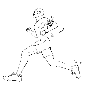
[0023] FIG. 1
generally discloses a person utilizing an athletic performance monitoring
and feedback system 1 that in one exemplary embodiment of the invention
includes a
wearable device assembly 10 having athletic functionality. As explained in
greater detail
below, the wearable device assembly 10 has a sensor associated therewith such
as a three-
axis accelerometer wherein the device 10 is capable of monitoring athletic
activity or overall
activity of the user. As shown in FIG. 1, the athletic performance monitoring
and feedback
system 1 may also include a further module or sensor 2, such as one carried by
or embedded
in a shoe, as well as a mobile device 3. It is understood that the system 1
could also employ
other types of sensors and devices if desired including a heart-rate monitor.
As discussed in
greater detail below, various components of the system 1 including the
wearable device 10
may wirelessly communicate with one another to record and monitor athletic
performance or
overall user activity. It is further understood that the person may utilize
only the wearable
device 10 to record and monitor athletic performance or overall activity. The
athletic
performance data or overall activity can include a variety of different
parameters, metrics or
physiological characteristics including but not limited to speed, distance,
steps taken, and
energy expenditure such as calories, heart rate and sweat detection. Such
parameters may
also be expressed in tei ____________________________________________ ins of
activity points (e.g., sometimes referred herein as "AP") or
currency earned by the user based on the activity of the user.
[0024] The shoe-
based sensor 2 may have various electronic components including a
power supply, magnetic sensor element, microprocessor, memory, transmission
system and
other suitable electronic devices. The sensor 2 in one exemplary embodiment is
mounted on
the shoe of a user as shown in FIG. 1. The sensor 2 is used in conjunction
with the other
12
CA 02950297 2016-12-01
=
components of the system to record data such as speed and distance among other
parameters
of athletic performance. The sensor 2 can be a sensor as disclosed in U.S.
Publication Nos.
2007/0006489; 2007/0011919 and 2007/0021269. These U.S. Publications are
incorporated
by reference and made a part hereof. The sensor 2 could also take the form of
a force-sensor
array to collect additional data associated with the user, such as disclosed
in U.S. Publication
Nos. 2010/0063778 and 2010/0063779, which are incorporated by reference and
made a part
hereof. The mobile device may be a smartphone or other types of portable
display devices.
The wearable device assembly 10 may also interact and communicate with other
types of
sensors including apparel based sensors or sensors associated with events such
as running
competitions or other athletic competitions.
[0025] FIGS. 2-6 illustrate different views of the wearable
device assembly 10 of FIG. 1.
The wearable device assembly 10 generally includes a housing 12, a controller
14, an input
button 16, a display 18, and an indicator system 20. It is understood that the
controller 14 has
and/or is operably connected to various associated components including power
supplies,
sensors and associated circuitry. FIG. 2a discloses an alternative device 10
having a larger
indicator system 20. The structure of the device 10 will first be described
followed by a
further description of the operation of the device and additional user
experiences provided by
the device and related systems.
[0026] The housing 12 is in the form of a wearable band such as
a wristband and
generally includes an inner spine member 22 (FIGS. 6-9) having compartments
for power
supplies, an outer encasement member 24, and a fastening mechanism 26 or latch
member
26. In certain exemplary embodiments, the housing 12 may have one or more
spacer
members 28 to adjust the size of the device 10 to be discussed in greater
detail below.
[0027] As further shown in FIGS. 2-6, the wearable device
assembly 10 is annular or
generally circular in shape and, in this illustrative example, is configured
for wearing around
a user's wrist. The wearable device assembly 10 may be formed in various other
shapes
without departing from the invention, such as oval, oblong, octagonal,
rectangular, and the
like. The device 10 may also be configured to be attached to a clip or other
device that can
be removably attached to a person, or incorporated into other apparel. The
wearable device
assembly 10 and the housing 12 may include a generally planar portion and
rounded or
beveled edges along the sides. The beveled edge may only be included on one
side of the
housing 12 in an exemplary embodiment. Ends of the housing are configured to
join with
13
CA 02950297 2016-12-01
one another via the fastening mechanism 26. In one or more arrangements, an
outward or
exterior facing side of housing 12 of the wearable device assembly 10 may
include a smooth
texture while an interior facing side (e.g., contacting the wearer's body) may
include
frictional features. In one example, the interior facing side of the wearable
device assembly
may be ribbed to improve traction and prevent slippage around a user's wrist
or other
body part. The texture may be even throughout the interior side or may be
uneven. For
example, the ribs or other texture may become more pronounced as the texture
progresses
away from the fastening mechanism formed at the ends of the housing. In other
arrangements, texture might also be added to an exterior side of the wearable
device
assembly 14 and the interior side may be smooth. Various combinations and
configurations
of textures may be used. In still other embodiments, the housing 12 may
incorporate sweat
absorption members on an inner diameter of the device 10 or wicking elements.
[0028] As shown in FIGS. 7-9, the inner spine member 22 is a member having
substantially rigid portions and certain flexible portions or zones. The spine
member 22
generally supports components of the controller 14 as described further
herein. The spine
member 22 may be considered a chassis member having various components
attached
thereto. The spine member 22 has a general curvilinear configuration and has
an outer
surface 30 and an inner surface 32. The spine member 22 has an intermediate
portion 34
that extends to a first distal end 36 and a second distal end 38. The
intermediate portion 34
has a central portion or central segment 40 as well as a first segment 42 and
a second segment
44. The intermediate portion 34 further has a first flexible zone 46 or member
that connects
one end of the central portion 40 to the first segment 42, and has a second
flexible zone 48 or
member that connects the other end of the central portion 40 to the second
segment 44. The
flexible zones 46,48 provide for more easy flexing of the spine member 22 at
these zones and
also the overall device while the first segment 42 and second segment 44, and
central portion
40, are considered rigid zones or substantially rigid zones. In an exemplary
embodiment, the
flexible zones 46,48 may be considered flexible hinge zones and are curved
segments in a
generally concave shape. Thus, the flexible zones have a central portion or
base portion with
a pair of members extending away from the base portion, and therefore define
an inwardly
curved portion. The curved segments have a thinned out thickness at the base
or central
portion of the concave configuration to enhance the flexible characteristics
of the flexible
zones 46,48. Thus, the spine member 22 has a general thickness or first
thickness along its
14
CA 02950297 2016-12-01
length (e.g., the rigid central portion and rigid first and second segments)
while the flexible
zones have a lesser, second thickness "t" to assist in the flexible
characteristics of the spine
member 22 and overall housing 12. In particular, the base portion of the
flexible zone has a
lesser thickness than the rigid central portion and first and second rigid
segments. As
explained in greater detail below, the flexible zones 46,48 assist in the
components supported
by the spine member 22 to be closest to a neutral axis wherein stresses are
minimized when
the device 10 is flexed such as when placing on a user's wrist or removing the
device 10 from
a user's wrist.
[0029] As shown
in FIGS. 7-9, the first segment 42 of the intermediate portion 34 has a
first recessed compartment 50 and the second segment 44 of the intermediate
portion 34 has a
second recessed compartment 52. These segments have a curvilinear
configuration. The
recessed compaitments 50,52 are dimensioned to receive power supplies
associated with the
controller 14. In an exemplary embodiment as shown in FIGS. 7a and 7b, the
recessed
compartments 50,52 are initially formed from a metal enclosure such as a thixo-
molded metal
member 55. A thixo-molded member is utilized in one exemplary embodiment while
other
members could also be used such as any cast metal members, die cast members or
any metal
injected molded members. Metal cover or closure members in the form of metal
caps are
also provided as described below to provide a metal enclosure for the power
supplies. It is
desirable to form a metal enclosure for the battery or batteries 142 and it is
understood that
the enclosure may include confronting metal members that may not form a
complete
chamber, but substantially surround the battery. It is understood that the
thixo-molded
compartments can be initially formed wherein the remaining portions of the
spine member 22
are formed over the thixo-molded compartments. Portions of the spine member
may be
formed over the thixo-molded members that define a bottom portion of the
compartments
50,52. The compaitments 50,52 further have a pair of openings 59 to receive
battery
teiminals or contacts to be described. The recessed compai __________ tments
50,52 may vary in size
generally or with respect to one another. Thus, the recessed compartments
50,52 may have
an increased size to accommodate larger power supplies having increased
capacity. Such
features will be described in greater detail below.
[0030] The
intermediate portion 34 further supports other components of the controller
14 proximate the outer surface 30 as well as the display 18 and indicator
system 20 as
described further below. The spine member 22 may have a beveled edge that
supports the
CA 02950297 2016-12-01
indicator system 20 thereon. The spine member 22 has certain openings to
receive fastening
mechanisms such as adhesives and screw fasteners to fixedly attach controller
components to
the spine member 22. The first distal end 36 and the second distal end 38
support the
fastening mechanism 26 and optional spacers 28.
[0031] In one exemplary embodiment, the thixo-molded members 55 that help
form the
compartments 50,52 are made from magnesium wherein the remaining portion of
the spine
member 22 is made from a polypropylene material that is formed over the
members 55. It is
understood that other materials could be used for the spine member 22 as well
as the battery
enclosures.
As shown in FIGS. 2, 3, 6 and 19, the outer encasement member 24 is positioned
around the
spine member 22 and encases the controller 14, the display 18 and the
indicator system 20.
In an exemplary embodiment, the outer encasement member 24 is a thermoplastic
elastomer
member that is formed in an injection molding process described in greater
detail below.
Accordingly, the outer casement member 24 has resilient elasticity while
maintaining an
annular shape. The outer encasement member 24 has a generally rounded outer
surface 56
and a generally planar inner surface 58, and may be considered to have an
inner portion
defining an inner diameter of the device 10 and an outer portion defining an
outer diameter of
the device 10. The outer surface 56 has a substantially large radius to form a
curvature while
almost appearing planar. The side edges have a smaller radius than the outer
surface and the
beveled side edge further has a small radius. The surfaces of the outer
encasement member
24 cooperate to foini an internal volume to house the various components of
the device while
maintaining a minimal cross-sectional dimension. The outer encasement member
further has
a beveled side edge 60. The indicator system 20 is positioned proximate the
beveled side
edge 60. It is understood that the housing 12 could have beveled edges on each
side edge if
desired. The outer encasement member 24 has an aperture 62 to accommodate the
input
button for interaction with the controller 14. The outer encasement member 24
has a first
region 64 to accommodate viewing of the display 18 and a second region 66 to
accommodate
viewing of the indicator system 20. It is understood that the first region 64
is structured and
dimensioned such that indicia projected by the display 18 can be viewed
through the first
region 64 of the outer encasement member 24. It is further understood that the
second region
66 is structured and dimensioned such that indicia projected by the indicator
system 20 can
be viewed through the second region 66 of the outer encasement member 24. The
outer
16
CA 02950297 2016-12-01
encasement member 24 may include a colorant providing a dark appearance. The
amount of
colorant is controlled such that the components encased by the outer
encasement member 24
cannot be seen. However, when the display 18 and indicator system 20 are
activated, light
easily projects through the outer encasement member 24 and is visually
perceptible. For
example, in one exemplary embodiment, the outer encasement member is
translucent
thermoplastic elastomer with a certain percentage of colorant. The outer
encasement member
24 may further be considered generally transparent but having a tint provided
by a certain
amount of black pigmented material. In this configuration, the internal
components within
the outer encasement member 24 are generally not seen, however, when the
display 18 and/or
indicator system 20 are activated, the light members are clearly seen through
the outer
encasement member 24. Thus, the internal components are not seen via the naked
eye, but
the display and/or indicator system can be seen through the outer encasement
member when
activated. The device 10 may further be configured such that one of the
display and indictor
system is always visible while the other one of the display and indicator
system is viewable
only upon activation. For example, the display may always be viewable such as
to show time
of day, while the indicator system is only viewable when activated. It is
further understood
that the outer encasement member 24 may be a clear material or include a
variety of different
colorants, or multiple colorants. Certain colors may indicate a device 10 is
specifically
designed for certain types of uses or events. The first region 64 and the
second region 66
may be constructed to be transparent. In an exemplary embodiment, these
regions are tinted
to a darker color wherein the display 18 and indicator system 20 are
illuminated therethrough.
It is understood that alternatively, openings can be provided at the first
region 64 and the
second region 66 for viewing the display 18 and indicator system 20. The inner
surface 58 of
the outer encasement member 24 has a first opening 68 and a second opening 70
proximate to
the location of the power supplies supported by the spine member 22. The first
opening 68 is
covered by a first cap 72 or closure member secured over the first opening 68
by fasteners,
and the second opening 70 is covered by a second cap 74 or closure member
secured over the
second opening 70 by fasteners. The first cap 72 and the second cap 74 are
formed from
metal materials to cooperate with the metal battery compartments 50,52 to
provide a metal
enclosure for the power supplies to be described. The outer encasement member
24 may be
composed of a variety of materials including a variety of polymers, plastics
or rubbers,
thermoplastic elastomer members, thermoplastic urethane members, liquid
silicone members,
17
CA 02950297 2016-12-01
and rubber composites, and other moldable elastic members, and/or synthetics
such as
neoprene, plastics, textiles, metals and/or combinations thereof. In one or
more examples, the
material may include thermo polyurethane and/or thermoplastic rubber. The
material used
may also offer some flexibility so that the size of the loop formed by the
wearable device
assembly 10 may be enlarged without fracturing or breaking the assembly 10. As
explained
in greater detail below, an adhesion promoter may be used on the spine member
22 and
components supported thereon to assist in adhesion of the outer encasement
member 24. The
spine member 22 and outer casement member 24 will be described in further
detail below
when describing the process of forming the device 10 below.
[0032] As shown in FIGS. 6 and 10-11, the fastening mechanism 26 or latch
member 26
generally includes a first projection member 90 and a second receiver member
92. The first
projection member 90 is positioned proximate the first end of the housing 12,
and the second
receiver member 92 is positioned proximate the second end of the housing 12.
It is
understood that the members 90,92 could be placed on opposite ends of the
housing 12 if
desired. The first projection member 90 incorporates an input/output member 94
for data
transfer and in an exemplary embodiment, takes the form of a USB connector 94
having a
substantially rigid body 96. The USB connector 94 includes a plurality of
leads 98 embedded
in a top surface of the rigid body 96. The leads 98 have connectors that are
operably
connected to the controller 14. As shown in FIG. 10c, the first projection
member 90 further
has a recess 100 positioned in a bottom surface of the rigid body 96 generally
opposite of the
USB leads 98. The bottom recess 100 defines an engagement surface 102.
[0033] As shown in FIGS. 6 and 1 la-f, the second receiver member 92
defines an
opening 104 therein and supports a pivoting member 106. The pivoting member
106 has a
finger portion 108 and includes a spring 110 to bias the finger portion 108
towards a latching
position. The pivoting member further includes a depressible button 112 to
move the finger
portion 108 away from the latching position. The second receiver member 92
further has a
pair of prong members 120 at an opposite end from the opening 104. The prong
member 120
has an inclined or curved cam surface 122. A slot 124 is defined along the
length of the
prong member 120.
[0034] As further shown in FIGS. 1 la-f, the first projection member 90 is
received into
the second receiver member 92 that may be connected to one end of the spine
member 22 in
18
CA 02950297 2016-12-01
an embodiment. Initially, the finger portion 108 is pivoted and biased away
from the latching
position. Once the finger portion 108 passes into the recess 100, the finger
portion 108 is
biased by the spring 110 into the recess 100 and to the latching position. The
device 10 is
then in a closed position wherein the finger portion 108 can abut the
engagement surface 102
to maintain the device 10 in a closed, annular configuration. While in an
exemplary
embodiment, the fastening mechanism 26 incorporates a traditional USB
connector 94, it is
understood that other types of connection configurations for communication
could also be
employed. For example, the device 10 may utilize a micro USB connector, a
Firewire port, a
16-pin pit, or other type of physical contact-based connection, or may include
a wireless or
contactless communication interface, such as an interface for Wi-Fi,
Bluetooth, near-field
communication, RFID, Bluetooth Low Energy, Zigbee, or other wireless
communication
technique, or an interface for infrared or other optical communication
technique. It is further
understood that the device 10 can be configured to communicate and data
transfer completely
from a data transfer member such as the USB connector 94, or completely via
wireless
communication, or a combination of both wireless communication and various
types of plug-
in communication.
[0035] FIGS. 10a-10c disclose additional views of the USB connector 94. The
USB
connector 94 has structural features that provide a cleaner, more
aesthetically pleasing
configuration while maintaining operability. In conventional USB connectors,
the leads are
spaced apart unevenly, are rectangular in shape, and respective ends of the
leads are not
aligned. As shown in FIG. 10a, the leads 98 of the USB connector 94 are evenly
spaced a
distance across the rigid body 96. In addition, the leads 98 are recessed with
respect to a top
surface 114 of the rigid body 96. In addition, the rigid body 96 defines
rounded openings 116
that are evenly spaced and wherein the ends of the openings 116 are aligned.
The leads 98
are exposed by the openings 116. Because the leads 98 are recessed with
respect the top
surface 114 of the rigid body 96, each lead 98 has a raised rib 118 that
extends proximate the
top surface 114 of the rigid body 96. In an exemplary embodiment, the leads 98
are placed in
a mold wherein material is injection molded around the leads 98 to form the
rigid body
having the uniform and aligned rounded openings 116. Such structure provides
an enhanced
USB connector 94.
19
CA 02950297 2016-12-01
[0036] The
device 10 may be varied in circumferential size wherein the device 10 can
define smaller and larger loop configurations to accommodate, for example,
different wrist
sizes of users. To this end, the housing 12 may incorporate a spacer member 28
or expansion
member or element 28 as shown in FIGS. 12-13. It is understood that a single
spacer
member 28 may be used or multiple spacer members 28 may be used, or not used
at all
wherein the device 10 simply has the latch mechanism connected at ends of the
housing 12.
The spacer member 28 cooperates with one end of the housing 12 and one end of
the receiver
member 92 of the fastening mechanism 26 to increase the circumferential size
of the device
10. The spacer member 28 has a body 130 having one end having a pair of
openings 132
dimensioned to receive the pair of prong members 120 positioned on the
receiver member 92
of the fastening mechanism 26. The body 130 supports a rotary pawl 134
proximate the
openings 132. The rotary pawl 134 has a curved cam surface 135 and has a
biasing spring
136. The rotary pawl 134 is secured generally at a central location to the
body 130 by a
fastener and cover plate shown in FIG. 12b. The rotary pawl 134 generally is
rotatable about
the central location. The other end of the body 130 supports a pair of prong
members 137
having cam surfaces 138 similar to the prong members 120 of the receiver
member 92. As
can be appreciated from FIGS. 1 If and 13, when using the spacer member 28,
the prong
members 137 of the spacer member 28 are received in and secured in openings in
an end of
the housing 12. This end of the housing 12 has corresponding structure to
receive such prong
members 137. The prong members 120 on the receiver member 92 of the fastening
mechanism 26 are inserted into the pair of openings 132 on the body 130 of the
spacer
member 28. To this end, the inclined cam surface 122 on the receiver member 92
engages
the cam surface 135 on the rotary pawl 134 wherein the rotary pawl 134 rotates
(Arrow A in
FIG. 12c having cover plate removed for clarity) allowing further insertion of
the prongs 120
into the openings 132. Once the slots 124 on the prong members 120 align with
the rotary
pawl 134, ends of the rotary pawl 134 are received in the slots 124 thereby
securing the
spacer member to the receiver member 92 of the fastening mechanism 26 (See
FIGS. 11f and
13). It is understood that access holes can be provided to rotate the rotary
pawl 134 when
desiring to remove the spacer member 28 from the device 10. It is understood
that multiple
spacer elements 28 may be used to increase size or spacer elements 28 could be
removed to
decrease size. The length of the spacer members 28 may vary and in some cases,
may range
from 5-10 mm. In one example, the length of the spacer elements 28 may be 8 mm
each. In
CA 02950297 2016-12-01
another example, the length of spacer members 28 may be 6 mm. It is further
understood that
if an expansion element 28 is not used, the prong members 120 on the receiver
member 92
cooperate with an end of the housing 12 to be secured thereto. In an exemplary
embodiment,
the spacer element 28 may have similar construction as the housing such as a
plastic body
having a thermoplastic member positioned over the body. The prong member 120
may be
part of a metal insert into the body. In certain exemplary embodiments, the
inner diameters
of devices 10 that may utilize spacer members can vary from approximately 147
mm to 221
mm.
[0037] The device 10 has the controller 14 that is supported by the housing
12. The
controller 14 generally includes a printed circuit board 140 having various
components
including circuitry, processing units, data storage memory, connectors and
other known
components as understood in the art (FIG. 43). The controller 14 further
includes a power
supply 142 in the form of a battery pack(s) or batteries 142, an antenna
assembly 144 and a
sensor assembly 146. The controller 14 could also have other components such
as a speaker
for conveying audible information. FIG. 43 discloses a block diagram of the
controller
showing additional components associated therewith and will be described in
greater detail
below.
[0038] FIG. 14 shows a schematic view of the printed circuit board (PCB
member) 140.
In an exemplary embodiment, the PCB member 140 is a flexible circuit member.
The PCB
member has various regions or sections to support the various components
thereon. The PCB
member further has a central region 140a wherein the display 18 and indicator
system 20 are
operably connected thereto. The PCB member also has flex regions 140b that
will
correspond in position to the flexible zones 46,48 of the spine member 22.
Other components
described herein are also connected to the PCB member 140. As shown in FIGS.
15 and 16,
the PCB member 140 is wrapped around and mounted to the spine member 22.
Fasteners
may be used to fixedly attach the PCB member to the spine member 22. It is
understood that
the central region 140a of the PCB member corresponds to the central portion
34 of the spine
member 22 when connected. The PCB member 140 generally follows the contours of
the
spine member 22 including the contours of the flexible zones 46,48. Thus, the
flex regions
140b are positioned at the flexible zones 46,48 of the spine member 22 and in
general
21
CA 02950297 2016-12-01
surface-to-surface engagement. This configuration allows the PCB member to be
moved
proximate a neutral axis wherein stress on the PCB member is minimized when
the device 10
is flexed.
[0039] As
discussed, the PCB member 140 supports the various components of the
controller 14. For example, the PCB member 140 supports the antenna assembly
144 and the
sensor assembly 146. The PCB member further supports data storage memory
components.
Data storage memory receives input from the sensor assembly and as well as
receives inputs
from the USB connector 94. Data stored by the controller 14 can also be
transferred via the
USB connector 94 to another device such as a computer and also to a remote
site via the
computer (FIG. 44).
[0040] The
antenna assembly 144 supported by the PCB member 140 assists in
communication with other mobile devices. Thus, the device 10 is capable of
wirelessly
communicating with mobile devices, and in one exemplary embodiment, the
controller 14
utilizes Blue tooth wireless communication. The controller 14 may, therefore,
have a
Bluetooth radio and utilizes the antenna assembly 144 wherein the device 10
may wirelessly
communicate with a mobile device. It is understood the device 10 is equipped
with other
necessary components for such wireless communication. Further examples of such
communication will be described in greater detail below.
[0041] As
discussed, the PCB member 140 supports a sensor assembly 146 thereon. The
sensor assembly 146 may comprise a plurality of different sensors. In an
exemplary
embodiment, the sensor assembly 146 comprises an accelerometer in the form of
a three-axis
accelerometer. As
explained in greater detail, the sensor 146 detects movement
corresponding to activity of the user wearing the device 10. It is understood
that the system 1
and/or controller 14 may also include other sensors as desired. For example,
the system 1
utilized by the user may utilize shoe-based sensors that communicate with the
device 10. The
user may also have apparel based sensors that can communicate with the device
10. It is
further understood that the sensor assembly 146 could include a heart rate
sensor. The heart
rate sensor could be chest mounted sensor if desired. It is understood that
the heart rate
sensor could also be incorporated into the housing 12 of the device 10 such as
a sensor that
22
CA 02950297 2016-12-01
detects heart rate proximate a wrist of the user. Other sensors could also be
utilized such as
GPS sensors. Additional sensors may also be incorporated into the device 10.
In one
exemplary embodiment, the sensor may include a gyroscope sensor. The sensor
may be a
microelectromechanical system (MEMS) type gyroscope device. Such a sensor may
cooperate with other sensors in the device such as the accelerometer to
provide enhanced
functionality and capabilities as well to provide further differentiation of
sensed movements
of the user.
100421 As
discussed, the controller 14 includes the power supply 142 in the form of
batteries 142. It is understood that a single battery 142 could be utilized in
the design. Such
a design may allow for a flexible circuit member having additional areas to
support additional
components associated with the device 10. In an exemplary embodiment, however,
the
power supply 142 utilizes a pair of batteries 142. As can be appreciated from
FIGS. 6 and
20, the batteries 142 have a curvilinear or curved configuration and are
generally rigid
members. The batteries 142 define curved planar surfaces. In an exemplary
embodiment, the
device 10 utilizes the pair of batteries 142. The first battery 142 is
positioned in the first
recessed compar ____________________________________________________ tment 50
of the spine member 22, and the second battery 142 is positioned in
the second recessed compartment 52 of the spine member 22. The batteries 142
have a
thickness that generally corresponds to a depth of the recesses 50,52. The
batteries 142 are
generally flush with the inner surface 32 of the spine member 22. It is
understood that the
batteries 142 are operably connected to the controller 14 to provide power to
the device 10.
As shown in FIG. 20, the batteries 142 have a resilient boot member 148
associated
therewith. The boot member 148 has a pair of rounded protrusions 149 and
battery contacts
150 of the batteries 142 are adhered over the round protrusions 149. The
batteries are
positioned in the recessed compartments 50,52 wherein the contacts 150 extend
through the
openings 59 in the compar __________________________________________ truents
50,52 and engage the PCB member 140 to provide power to
the device 10. When the caps 70,74 are fastened down on the spine member 22,
the round
protrusions 149 and contacts 150 are resiliently pinched against the PCB
member 140
providing an enhanced conductive connection. It is understood that each
battery 142 utilizes
a resilient boot member 148. In additional exemplary embodiments, a conductive
epoxy
member may be used to join the battery contacts. The overall size of the
batteries 142 and
respective recessed compartments 50,52 may vary such being larger to increase
battery
23
CA 02950297 2016-12-01
capacity and life of the device before requiring recharging. It is appreciated
that the rigid
batteries 142 are mounted in the more rigid first segment 42 and rigid second
segment 44 of
the spine member 22. The flexible zones 46,48 of the spine member 22 allow the
segments
42,44 and batteries 142 to hingedly pivot about the flexible zones 46,48 to
provide a
generally flexible housing 12 and device 10.
[0043] As shown in FIGS. 2-6 and 16-19, the device 10 includes a
depressible input
button 16 assist in operation of the device 10. As can be appreciated from
FIGS. 17 and 18,
the input button 16 is operably connected to the controller 14 and supported
by the housing
12 generally adjacent the display 18. The input button 16 is accessible to the
user via the
input button 16 extending past the outer encasement member 24 of the housing
12. The input
button 16 has a rigid base member 76 and a flexible cap 78 integrally formed
together in a
two-shot molding process. An internal chamber 79 is defined by the input
button 16 to
support a tact switch that can interact with the controller 14. The rigid base
member 76 has
an upper ring 80 defining a first tool surface 82 and a lower ring 84 adjacent
the flexible cap
78 and defining a second tool surface 86. During the process of forming the
device 10, the
first tool surface 82 and the second tool surface 86 engage a tool in tight
surface-to-surface
engagement when the outer encasement member 24 is injection molded around the
spine
member 22 and supported components. This engagement prevents the injection
molded
material from flowing into the internal chamber 79 of the input button 16
which would
prevent the input button 16 from operating correctly. Operation of the device
10 from inputs
provided via the input button 16 will be described in greater detail below.
[0044] As shown in FIGS. 2 and 15 and 16, the display system 18 or display
18 of the
device 10 is supported by the housing 12 and operably connected to the
controller 14. The
display may be considered an illuminable portion of the device 10 or housing
12. The
display system 18 may include a series of individual lighting elements or
light members such
as LED lights 152 in an exemplary embodiment. The LED lights may be formed in
an array
and operably connected to the PCB member 140 at the central location. The LED
lights 152
may be arranged such that words, letters, numbers, symbols and the like may be
produced by
lighting various combinations of the individual discrete LED lights 152. For
example, LED
lights 152 may be arranged in a matrix formation baying a specified number of
rows and
24
CA 02950297 2016-12-01
columns. The outer encasement member 24 of the housing 12 surrounds and
protects the
LED lights 152. As discussed, the outer encasement member 24 has the first
region 64 (FIG.
19) and corresponds to the locations of the LED lights 152 so that once the
LED lights are
illuminated, the light is visible through outer encasement member 24 (in an
alternative
embodiment, the first region 64 could be made transparent or substantially
transparent). It is
understood that the first region may be individual and discrete. For example,
each of the
illumination regions may be surrounded by non-transparent or opaque portions
of the outer
encasement member 24 such that illumination from each of the LED lights 152
does not
blend together. The display system 18 may span only a portion of the total
circumference of
the wearable device assembly 10. For example, as illustrated in FIG. 2, the
display system 18
occupies a top portion or central portion of the device 10 opposite the
fastening mechanism
26. The size of the display system 18 (e.g., the number of individual LED
lights, number of
rows and columns of lights, an overall width or length) may be determined
based on a
maximum amount of data to be displayed at any one time, a size of the font
and/or characters
to be used and/or combinations thereof. In one example, the display system 18
may be
composed of 5 rows of 20 LED lights 152, wherein each row is substantially
parallel to the
length of wearable device assembly 10. Additionally or alternatively, the
overall exterior
circumference (e.g., of an outward facing surface of the device assembly 14)
may range from
174-182 mm. It is also understood that the display 18 could include a light
member
indicating the device 10 is communicating via wireless connection such as
Bluetooth
communication with a mobile device.
[00451 As also shown in FIG. 2 and 15 and 16, the indicator system 20 of
the device 10 is
supported by the housing 12 and operably connected to the controller 14. The
indicator
system 20 may also be considered a portion or component of the overall display
18. The
display system of the device 10 may be considered to have a first display and
a second
display. It is understood that the indicator system 20 can operate and
illuminate in
conjunction with the display 18 or completely separate from the display 18.
The indicator
system 20 may also include a plurality of additional lighting elements 160 or
light members
160, which may also take the form of LED lights in an exemplary embodiment.
The light
members 160 are operably connected to the controller 14 and supported by the
PCB member
140. The indicator system 20 is positioned generally at the side edge of the
housing 12. In
CA 02950297 2016-12-01
one particular example, the indicator system 20 may include a series of twenty
lighting
elements 160. Optionally, lighting elements 41 may run along both side edges
of the housing
12 of the wearable device assembly 10. The lighting elements 160 are also
positioned in a
generally linear configuration in an exemplary embodiment. The lighting
elements 160 of the
indicator system 20 may be differently shaped from lights 152 of the display
system 18. The
difference in shape, size or other appearance attribute may allow a user to
identify the type of
information being conveyed. The lighting elements 160 may, for example, line
one or more
of the beveled side edges 60 of the housing 12 of the wearable device assembly
10, allowing
for ease of viewing by the user. In the example where the sides or edges of
wearable device
assembly 14 are rounded, the lighting elements 160 may be positioned on an
outer curvature
of the rounded edges such that light may be seen when worn (e.g., facing away
from the
user's wrist or other body part on which the device 14 is worn). Similar to
the configuration
of lights 152 of the display 18, the outer encasement member 24 has the second
region 66
(FIG. 19) that is at locations corresponding to the position of lighting
elements 160 of the
indicator system 20. Light projected from the light members of the indicator
system 20 are
viewable through the outer encasement member 24 at the second region 66 (in
alternative
embodiments, the second region 64 could be transparent or substantially
transparent). In one
or more arrangements, the appearance of illumination produced by lighting
elements 160 may
be defined by the size, shape, transparency and other appearance attributes of
a corresponding
portion of the outer encasement member 24. For example, the lighting elements
160 might
actually be circular (e.g., circular bulbs) but may be used to illuminate
transparent rectangular
regions of the outer encasement member 24, thereby producing rectangular
indicators (See
e.g., FIG. 2a). The plurality of lights 160 of the indicator system 20 may
extend around a
portion of the circumference of device assembly 10. In one example, the
plurality of lights
160 of the indicator system 20 extend generally the same length of the length
of the display
18. Spacing between the various plurality of lights of the indicator system 20
and display 18
may also be similar. In another example, the light members 160 may extend
around
approximately half of the circumference while in other examples, indicators
light members
160 may extend around approximately a third of the circumference. In yet
another example,
the light members 160 may extend around three-quarters or substantially the
entire
circumference of the wearable device assembly 10. It is also understood that
the plurality of
lights 160 comprising the indicator system may be grouped together wherein the
indicator
26
CA 02950297 2016-12-01
system may have different segments. The different segments of the indicator
system 20 may
be illuminated in different configurations as described in greater detail
below. Each lighting
element 160 may also be considered a separate individual segment of the
display. From the
configuration of the display 18 and indicator system 20, it is understood that
the display 18
may project light in a first direction, and the indicator system 20 may
project light in a second
direction 20, wherein the first direction is different from the second
direction. In one
exemplary embodiment, the second direction may be generally transverse to the
first
direction. It is also understood that the light members of the displays could
take other various
faints and structures that provide illuminable characteristics.
[0046] FIGS. 39-42 are schematic views illustrating a molding process for
creating a
wearable device assembly according to aspects of the invention. In FIG. 39, a
first mold 170
may be used to create the spine member 22 of the wearable device assembly 10.
As
discussed, the structural features of the spine member 22 allow the
attachment, insertion and
mating of various electronic and non-electronic components of the wearable
device assembly
10. The spine member 22 may be molded from a plastic material such as a
thermoplastic
material injected into the mold 170. The spine member 22 may be thinner in
some portions
such as the flexible zones to provide flexibility in those regions. In
contrast, other portions
such as the segments supporting the batteries may be thicker to provide more
rigidity. In
addition, the electronic components such as circuits and lighting elements
(e.g., LEDs) may
be attached to more rigid portions to prevent breakage. Subsequently, the
spine member 22
may be assembled with other components as described above. For example, the
battery packs
142, circuits, display 18 and indicator system 20 may be assembled with the
spine member
22.
[0047] As further shown in FIG. 40, the assembled spine member 22
supporting certain
of the various components may then be wrapped or loaded onto an insert core
172 for further
injection molding. An interior diameter, or inner portion, may then be
injection molded onto
the spine member 22. In FIGS. 41 and 42, the molded assembly may then be
inserted into an
outer diameter mold 174 and an outer diameter, or outer portion, of the
wearable device
assembly 10 may be molded to completely form the outer encasement member 24 of
the
housing 12. The device assembly 10 can then be removed from the insert core
172.
27
CA 02950297 2016-12-01
[0048] It is understood that additional processes can be utilized in
forming the device
such as the device 10 shown in FIGS. 1-6. In an exemplary embodiment, a
process of
forming the spine member 22 initially includes forming the battery
compattmeuts. As can be
appreciated from FIGS. 7a, 7b, 8a and 8b, a mold is provided wherein via a
thixo-molding
process, magnesium is injected into the mold to form the thixo-molded members
55. The
magnesium thixo-molded members 55 cooperate with the metal battery caps 70,74
(FIG. 2)
to provide a substantially metal enclosure for the batteries 142. As
discussed, other metal
forming processes can be used. Once formed, the thixo-molded members 55 are
placed in a
mold wherein material is injected into the mold to form the spine member 22.
The material is
overmolded around the thixo-molded members 55 wherein a certain amount of
injected
material extends over an internal surface of the members 55 (FIGS. 7-8). It is
understood that
the mold is designed to incorporate forms for the substantially rigid portions
of the spine
member 22, the flexible zones 46,48 of the spine member 22 as well as other
structures for
receiving, mounting or otherwise supporting the various components of the
device 10 as
described herein. In an exemplary embodiment, the material injected over the
thixo-molded
members 55 to form the remaining portions of the spine member 22 is
polypropylene.
[0049] Once the spine member 22 is formed, additional components are
connected to the
spine member 22. For example, one end of the spine member 22 can be connected
with
connection structure that will cooperate with either one of the latch
mechanism or a spacer
element. It is further understood that the USB connector 94 is formed having
the features
described above. As can be appreciated from FIGS. 10a-10c, the USB leads 98
are provided
having the raised ribs 118 formed such as through a stamping process. The
leads 98 are
placed in a mold wherein plastic injection molded material is formed around
the leads 98 to
form the rigid body 96 around the leads 98. It is understood that the mold is
designed such
that the rounded openings 116 are formed and wherein the leads 98 are then
spaced apart
equally and vertically aligned. While the leads 98 are recessed in the rounded
openings, the
raised ribs 118 extend to proximate a top surface 114 of the rigid body 96.
The mold is also
designed to form the recess 100 in the rigid body 96 of the USB connector 94.
Once formed
the USB connector 94 is connected to an end of the spine member 22 while ends
of the leads
will be ready to be connected to the controller (FIG. 9).
[0050] The spine member 22 with the attached components may then be
inserted into a
mold wherein an inner diameter portion of the device is overmolded. A
thermoplastic
CA 02950297 2016-12-01
elastomer material is injected into the mold to form the inner portion of the
housing 12. It is
understood that an adhesion promoter may be used wherein the adhesion promoter
is applied
to the inner surface of the spine member 22 prior to overmolding the
theintoplastic elastomer
material. The adhesion promoter assists enhances the bonding of the
thermoplastic elastomer
material to the spine member 22. In one exemplary embodiment, 3M Primer 94
sold by the
3M company is used as the adhesion promoter. It is also understood that the
molds are
designed such that openings are provided in the inner portion of the housing
12 that are in
communication with the recessed compartments 50,52 that will receive the
batteries 142.
[0051] Additional components are then ready to be attached to the spine
member. As can
be appreciated from FIGS. 15 and 16, the PCB member 140 of the controller 14
is formed
with the necessary circuitry, other electrical components, antennas, as well
as the required
sensors including the three-axis accelerometer. In addition, the display 18
and indicator
system 20 components are also connected to the PCB member 140. It is further
understood
that the input button 16 is formed in a two-shot injection molding process
wherein the rigid
base member is integrally connected to the flexible cap (FIGS. 17-18). The
input button is
also connected to the PCB member 140. The PCB member 140 is connected to the
spine
member 22. The PCB member 140 is wrapped onto the spine member and follows the
contours of the spine member 22 generally in surface-to-surface engagement
including at the
flexible zones 46,48 of the spine member 22. (FIGS. 6, 15, 16) The PCB member
140 is
fixedly attached to the spine member 22. As discussed, this configuration
assists in providing
a more neutral axis wherein stresses from flexing are minimized. The ends of
the leads of the
USB connector 94 are also soldered onto the PCB member 140. The batteries 142
are
inserted into the battery compartments (FIGS. 19-20). The raised contacts are
positioned
through the openings 59 in the battery compartment 50,52 wherein the contacts
mate with
receiving contacts on the printed circuit board. The battery closure members
are fixedly
attached to the inner portion of the device via screw fasteners (FIG. 2)
wherein the battery
contacts are biased against mating contacts associated with PCB member 140.
[0052] This intermediate assembly is then inserted into an additional mold
for an
additional overmolding process. The mold includes a tool that engages the
first ring surface
82 and the second ring surface 86 of the input button 16 to prevent the
thermoplastic
elastomer material from migrating into the internal portions of the input
button 16 (FIGS. 17-
18). The thermoplastic elastomer material is injected into the mold to
complete formation of
29
CA 02950297 2016-12-01
the outer encasement member 24. In one exemplary embodiment, the spine member
22
includes a tube structure having a port opening 380 wherein the material is
injected through
the tube structure to form the outer portion of the outer encasement member
24. As shown in
FIG. 19a, the port opening 380 is provided in an inclined surface in the
battery compartment
52 and is in communication with the tube structure through the spine member
22. Once
placed in the appropriate mold member, the injected material is injected
through the port
opening 380 and flows in the mold to form the outer portion of the outer
encasement member
24. It is understood that the port opening 380 could be located in either
battery compartment
or in other locations on the spine member 22. The port opening 380 could
further include
multiple port openings. Thus, the various components supported on the spine
member 22 are
encased in the outer encasement member 24. The thermoplastic elastomer
material flows to
and engages with a side surface of the input button 16 wherein further
migration of the
material is prevented by the tool (See FIG. 6). Once the overmolding process
is complete,
the receiver portion of the latch mechanism and any desired spacer element can
be attached
(FIGS. 2, 3 and 19). In such configuration, it is understood that the housing
12 is easily
flexible to allow for placing the device on a wrist of a user. The device 10
flexes at the
flexible zones 46,48 of the spine member 22 wherein it is understood that the
rigid segments
with the batteries 142 mounted thereon move together. The elastic properties
of the outer
encasement member 24 readily allow for such pivoting while providing
sufficient structure to
protect the components supported by the spine member 22.
[0053] The device 10 is then formed and ready for operation (FIG. 2).
Operation and
other user experiences are described below.
[0054] The device 10 of the present invention has numerous alternative
structures and
configurations. For example, FIGS. 21-38 disclose additional embodiments of
various
components of the housing 12, controller 14, display 18 and indicator system
20 that can be
utilized in the device 10 and combined with features of the device 10
described above.
100551 FIGS. 21a-d illustrate schematic side views of alternative
embodiments of spine
members and batteries that can be used with the device 10 of the present
invention. Similar
structures may be referred to with similar reference numerals. The spine
member 22a has the
multiple flexible zones 46a,48a along with the rigid or substantially rigid
segments or zones
CA 02950297 2016-12-01
42a,44a. FIGS. 21a-d illustrate the flexible zones in the form of thinner
portions of the spine
member 22a. The thinner portions may correspond to more flexible regions while
thicker
portions of the spine member 22a may correspond to more inflexible areas or
rigid zones. It
is understood that the spine member 22a more easily flexes or hingedly pivots
about the
flexible zones. The rigid zones 42a,44a might not be flexible to allow for non-
flexible
components such as circuit boards, lighting systems, battery packs and other
electronics
assemblies to be secured. For example, the rigid zones 42a,44a may each
include a battery
pack 142. Additionally or alternatively, one or more of rigid zones 42a,44a
may include
circuitry for processing, storing and/or sensing athletic information. The
display component
may be disposed in an additional central rigid zone generally extending
between the rigid
zones 42a,44a supporting the batteries. The rigid zones 42a,44a may have a
limited amount
of flexibility to at least allow for a predefined amount of expansion of
device assembly 10.
[0056] As further can be appreciated from FIGS. 21a-21b, the lengths of
battery packs
142 can be adjusted to increase or decrease battery capacity. Due to the
changes in the
lengths of the battery packs 142, the length or other dimension of display
components,
indicator system components, or other controller components can also be
affected. For
example, if the length of battery packs 142 is increased, the size of the
display or display may
be decreased to compensate. Similarly, in FIGS. 21c-21d, the thickness of the
battery packs
142 may be modified to adjust battery capacity and device life. By increasing
thickness of
the device rather than length, the size of flexible zones may be maximized
since there is no
expansion of the battery pack 142 along the length of device assembly 10.
However,
increasing thickness may also increase weight and/or device circumference. The
batteries
142 and rigid segment or zones 42a,44a may be cooperatively dimensioned to
provide a
device 10 having a suitable capacity to record activity and display
information prior to
requiring recharging.
[0057] FIGS. 22 and 23 disclose components of a controller according to an
alternative
embodiment of the invention. Similar components may be referred to with
similar reference
numerals. The PCB member 140 supports other components of the controller 14.
The
indicator system 20 may also be provided with separate light member
compartments 180 and
a cover member 182 positioned over the light members of the indicator system.
An
additional cover member 184 may be positioned over the PCB member 140 as shown
in
3
CA 02950297 2016-12-01
FIGS. 23a-c. It is understood that the controller as shown in FIGS. 23a-c can
then be
wrapped onto a spine member 22 and fixedly attached thereto.
[0058] FIGS. 24-27 disclose display components of an alternative embodiment
of the
device 10. FIG. 24 discloses an exploded view of components of a display
according to an
alternative embodiment of the invention. Similar components may be referred to
with similar
reference numerals. The display 18 in this embodiment has a plurality of light
members 152
operably connected to the PCB member 140 of the controller 14 and mounted to
the spine
member 22. A seal member 190 has an opening therethrough and shaped to be
positioned
around the peripheral edges of the plurality of light members 152. A first cap
member 192
'having a plurality of apertures therethrough is positioned over the plurality
of light members
152. The apertures are positioned to correspond to respective light members. A
pair of
additional transparent cover members 194 is positioned over the cap member
192. A single
transparent cover member could also be utilized. As can be appreciated from
FIG. 24, the
seal member 190, cap member 192 and cover members 194 are positioned over the
plurality
of light members 152 of the display 18. The cap member 192 is sandwiched
between the seal
member 190 and the cover members 194. When the plurality of light members 152
are
illuminated, light can pass through the apertures of the cap member 192 and is
viewable
through the cover members 194.
100591 FIGS. 25a and 25b disclose the cap member 192 in greater detail. The
cap
member 192 is configured to be positioned over the plurality of light members
152 of the
display 18. The cap member 192 has a convex outer surface. FIG. 25b discloses
an
underside view of the cap member 192 shown in FIG. 25a. The cap member 192 has
the
plurality of apertures that generally correspond to the position of the
plurality of light
members 152 of the display 18. As further shown in FIG. 26, each aperture is
in
communication with a column 196 extending into the underside of the cap member
192. As
shown in FIGS. 26 and 27, each column 196 has a general frusto-conical shape.
A bottom
portion of the column is dimensioned to completely surround the light member
152 of the
display 18. As can be appreciated from FIGS. 26 and 27, the cap member 192 is
positioned
over the plurality of light members 152 wherein each light member 152 is
positioned within a
respective column 196 of the cap member 192. The outer encasement member 24 of
the
device 10 is positioned over the cap member 192 and is structured and
dimensioned such that
when the light member is illuminated, light is viewable through the outer
encasement
32
CA 02950297 2016-12-01
member 24. As shown in FIG. 27, when the light member is illuminated, the
frusto-conical
column 196 assists in reflecting light such that the light if directed in a
more focused manner
through the aperture and outer encasement member 24. It is understood that the
outer
encasement member in this embodiment could have an opening wherein the clear
cover
members 194 extends past the opening and wherein the light members are
viewable through
the opening.
[0060] FIGS. 28 and 29 show additional alternative embodiments of a
display. In FIG.
28, a thin, transparent cover member 198 is positioned over the plurality of
light members
152 of the display. A cap member 200 having a plurality of interconnected caps
is positioned
over the plurality of lights. Each cap is dimensioned to fit over a respective
light member.
FIG. 29 also shows a display utilizing a transparent cover member 202 over the
plurality of
light members 152. A cap member 204 having a plurality of apertures is
positioned over the
cover member 202.
[0061] FIG. 30 shows a partial cross-sectional view of the USB connector
94. The USB
connector 94 is connected to a distal end of the spine member 22. The USB
connector has
the plurality of USB leads 98 and wherein the USB leads 98 include ribs
thereon thus having
raised configuration. As further shown in FIG. 30, the USB leads are connected
to
connectors that extend through the spine member 22 and are operably connected
to the
controller 14.
[0062] FIGS. 31-33 illustrate an alternative fastening mechanism that can
be used in the
device 10 of the present invention. The fastening mechanism 300 has
cooperating
components that can be operably associated with the housing 12 of the device
10. The
fastening mechanism 300 generally has a first projection member 302 and a
second receiver
member 304. Similar to prior embodiments, the fastening mechanism incorporates
a USB
device that is configured to attach to one end of a housing 12 of the device
assembly 10 on
one side and to connect to a receiving end on the housing 12 on the other
side. For example,
as shown in FIGS. 31a and 3 lb, a USB connector 306 incorporated into the
first projection
member 302 is insertable into the second receiver member 304. The USB
connector is
similar in structure as prior embodiments and has a plurality of leads. The
receiver member
304 includes an opening 308 or slot having a shape and size corresponding to
the size and
shape of the USB connector 306. The opening 308 of the receiver member 304 may
include
33
CA 02950297 2016-12-01
a spring-loaded latch 310 that is configured to secure the USB connector 306
to the receiver
member 304 upon insertion. The opening 308 or slot may extend through the
entire receiver
member 304 in a lengthwise direction. The length of the receiver member 304
may be less
than the entire length of USB connector 306. In one example, the length of the
receiver
member 304 may correspond to approximately one-half or one-third of the length
of the USB
connector 306. The spring-loaded latch 310 may extend out of and past a rear
portion of the
receiver member 304 to align with one or more portions of the USB connector
306 when the
USB connector 306 is fully inserted into receiver member 304.
[0063] FIG. 32a illustrates an interior view of the receiver member 304.
The latch 310
pivots around a spring 312 and biases the latch 310 to a latching position.
The latch 310 also
has a finger 314 and a button 316 for activating the latch 310. The latch
finger 314 pivots in
an opposite direction to the button 316. By pressing the button 316, the
finger 314 may be
dislodged from the USB connector 306 (FIGS. 31a-3 lb), allowing the USB
connector 306 to
be removed/detached from receiver member 304.
[0064] FIG. 32b illustrates a bottom surface of the USB connector 306
configured to
engage with the latch 310 of the receiver member 302. The bottom surface of
the USB
connector 306 has a recess 318 which defines an engagement surface 320,
wherein the latch
310 is configured to engage the surface when USB connector 306 is inserted. In
the
illustrated arrangement, the recess 318 is on a surface of the USB connector
306 opposite the
USB connector leads.
[00651 Because the receiver member 304 may be shorter than the overall
length of the
USB connector 306, the end of the housing of the wearable device assembly 10
may include
an opening having a length equal to a length of the USB connector 61 that
remains exposed
after insertion into receiver member 304.
[0066] FIGS. 33a-33d illustrate a process by which the USB connector 306 is
inserted
into the receiver member 304 and a further opening in an end of the housing 12
of the
wearable device assembly 10 to which the receiver member 304 is attached. In
FIG. 33a, the
latch 310 may initially be biased such that finger 314 protrudes into the
opening in the
housing 12. As the USB connector 306 is inserted into the opening 308 of the
receiver
member 304 and into the additional opening (as illustrated in FIG. 33b), the
finger 314 may
be forced downward by the USB connector 306 contacting an inclined surface of
the finger
314. Upon the USB connector 306 being inserted into the receiver member 304
and the
34
CA 02950297 2016-12-01
opening to a point where the recess 318 is aligned with the latch 310, the
finger 314 may
protrude into the recess 318 and engage the engagement surface 320 due to the
spring bias as
illustrated in FIG. 33d. This engagement provides a secure connection between
the USB
connector 306 and the receiver member 304. Accordingly, a fastening mechanism
is
provided between the ends of the housing of the device 10.
100671 FIGS. 34a and 34b disclose a spacer assembly or expansion element
used to
increase the size of the wearable device assembly 10, and also can be used
with the fastening
mechanism 300 shown in FIGS. 31-33. The expansion element may also include an
opening
336 into which a portion of a USB connector 306 may be inserted and engaged.
FIGS. 34a-
34b, for example, illustrates an expansion element 330 having a connector
portion 332
configured to mate with and connect to an opening 334 in the housing 12. This
connection
can take various forms. For example, a shape of the connector portion 332 may
match the
shape and size of opening 334. To facilitate the use of the expansion
elements, the receiver
member 304 may be removably detachable from the main body of the wearable
device
assembly 10. The expansion element 330 may then be inserted between receiver
member
304 and the end of the housing 12. Clasps or other types of fastening
mechanisms might also
be included in the opening 334 and/or connector portion 332 to provide a
secure attachment.
One end of the expansion element 330 may include an opening 336 that is of
similar shape
and size to the opening 334 in the end of the housing 12. This allows the USB
connector 306
to mate with the opening 336 in the expansion element 330, in the event a user
wishes to use
one or more expansion elements. FIG. 34b illustrates the overall device
assembly upon
insertion of the extension element 330 and connection of the USB connector
with the
receiving portion.
[0068] FIGS. 35-37 illustrate another example alternative fastening
mechanism in which
a micro USB connector may be used instead of a full sized USB connector. In
this
arrangement, the micro USB connector may be tapered in shape to help simplify
the
engagement between the micro USB connector and the receiving portion of the
other end of
the wearable device assembly 10. The fastening mechanism 350 has cooperating
components
that can be operably associated with the housing 12 of the device. The
fastening mechanism
300 generally has a first projection member 352 and a second receiver member
354.
CA 02950297 2016-12-01
[0069] As illustrated in FIGS. 35a-c, the first projection member 352
supports a micro
USB connector 356. The micro USB connector 356 may include metal pins 358 that
may be
used to secure the micro USB connector end 356 to the receiver member 354 of
the wearable
device assembly 10.
[0070] FIGS. 36a and 36b illustrate different perspective views of the
receiver member
354. As illustrated, the receiver member 354 has an opening having hook
members 360
supported therein for latching onto the metal pins 358 (of FIGS. 35b and 35c).
In an
exemplary embodiment, the hook members 360 may be biased with a spring member
362 and
moveable against the spring bias by a depressible button 364.
[0071] FIGS. 37a-e illustrates an example process by which the micro USB
connector
356 of the first projection member 352 is connected to the receiver member
354. As the
micro USB connector 356 is inserted into the opening of the receiver member
354, inclined
surfaces of the hook members 360 engage the metal pins 358 and are forced
upwards against
the force of the spring 362. Once inserted further into the opening, the hook
members 360
pass beyond the metal pins 358 wherein the spring 362 biases the hook
downwards wherein
the hook members 360 engage against the pins 358 wherein the latch mechanism
is in a
latched position. The user may depress the button 364 to disengage the members
352,354.
[0072] FIGS. 38a and 38b illustrate views of the fastening mechanism 350 of
FIGS. 35-
37 using an expansion element 370. In particular, the receiver member 354 may
be
removably detachable from the housing 12 of the wearable device assembly 10 so
that
expansion elements such as the expansion element 370 may be inserted between
the receiver
member 354 and the housing 12 of the wearable device assembly 10. Each
expansion
element 370 may include an opening 372 into which receiver member 354 may be
inserted
and secured. FIG. 38b illustrates a wearable device assembly 10 having the
micro USB
connector 356 and the expansion element 370 or spacer inserted.
[0073] It is understood that other alternative fastening mechanisms could
be utilized to
releasably connect distal ends of the housing 12 of the wearable device
assembly. Other
structures could include interference fit connections, hook and loop
fasteners, or other buckle
type configurations. The housing 12 could also have a permanent annular
configuration
while having an expanded configuration to allow a user to fit the assembly
onto the wrist etc.
36
CA 02950297 2016-12-01
[0074] As discussed and shown herein, the various components of the
wearable device
assembly 10 are connected and supported by the spine member 22 wherein the
elastomer
material is formed over the components to place the device 10 in its final
form as shown in
FIGS. 1 and 2. As can be appreciated from the Figures, the fastening mechanism
26 can be
unlatched wherein the device 10 can be positioned around a wrist of the user
and the
fastening mechanism 26 can be subsequently placed in a latched position. The
user can wear
the device 10 at all times if desired.
[0075] When worn by the user, the device 10 can track activity of the user.
It is
understood that the controller 14 of the device 10 has certain algorithms
associated with the
controller and sensor to process and utilize data sensed by the sensor(s). It
is understood that
the controller can utilize a single algorithm or multiple algorithms as
desired. Certain
algorithms may be utilized for specific activity engaged in by the user. The
controller 10 can
also be configured such that certain algorithms are automatically selected
based on the data
sensed by the sensor. In an exemplary embodiment, an input can be provided to
the device
for activation wherein the device 10 begins tracking activity of the user. For
example, the
sensor such as the three-axis accelerometer can sense movement of the user
wherein the
device 10 records data associated with such movement. Activity tracked can
vary including
steps taken by the user, energy expended by the user or other metrics or
parameters. Certain
parameters tracked can also include speed and distance, heart rate, or other
parameters.
Additional processing may be employed with the sensor, algorithm and sensed
data. In one
exemplary embodiment, the device 10 may utilize a transfer function/algorithm
that translates
the data measured by the accelerometer and energy expenditure, wherein
acceleration is
mapped to approximate oxygen kinetics (calories burned). The display and/or
indicator
system may display indicia indicative of such activity. The device may also
wirelessly
interact with a mobile device associated with the user or a remote website
such as a site
dedicated to fitness or health related subject matter. At some predetermined
time, the user
may wish to transfer data from the device to another location. As shown in
FIG. 44 the user
may unlatch the device 10 and plug the USB connector 94 into a computer. In
response, data
stored on the device 10 may be transferred to the user's computer and/or to a
remote site fir
further processing and display. Data may also be loaded onto the device 10
from the user's
computer or remote site. The device 10 and/or computer may be configured such
that the
37
CA 02950297 2016-12-01
user is prompted to commence a data transfer or the data transfer can commence
automatically once the device 10 is plugged into the port of the computer.
Such data may be
configured to trigger operational events on the device 10 such as illuminating
the display or
indicator system based on time, activity currency or other variables. When the
device 10 is
plugged into a computer to sync and transfer data, certain light members of
the indicator
system may be illuminated to indicate a syncing process. The batteries of the
device 10 are
also charged when the USB connector 94 is plugged into the user's computer. It
is
understood that the device 10 can also be configured such that data transfer
and/or device
charging can be done via wireless and/or wired connections. For example, the
device 10 may
be configured for re-charging batteries via induction charging. The device 10
could also be
configured to automatically transfer data wirelessly if the device 10 senses
another suitable
paired device. Once a syncing process is complete and the device 10 is
sufficiently charged,
the device 10 can be removed from the computer, and again worn by the user and
activated to
begin detecting activity. Further user interfaces and user experiences
associated with
operation of the device will be described below. In some arrangements, the
indicator system
(e.g., indicator system 20) may be a second display. The indicator system 20
and the display
18 may be controllable independently of one another.
[0076] FIG. 43
is an example block diagram of a wearable activity detection and tracking
device 4300. The device may include a variety of components including a main
controller or
host processor 4301 configured to execute instructions and control other
components of the
device 4300 in accordance with the instructions. The device 4300 may further
include
memory for storage of data and instructions including volatile and non-
volatile memory such
as random access memory (RAM) 4303, read-only memory (ROM) 4305 and storage
4307.
Additionally, the device 4300 may include a charging component 4309 for
charging one or
more batteries (not shown) powering the device 4300. The device 4300 may
further include
various input and output adapters and other components including an ambient
light sensor
4311, a display adapter 4313, an accelerometer 4315 and input adapter 4317.
Ambient light
sensor 4311 may be used to determine a level of brightness for one or more
displays for
viewability. Light sensor 43 11 may also be used to determine a general time
of day. Input
adapter 4317 may be configured to receive and process various types of input
including
button presses, touch input, scroll wheel input and the like, depending on the
types of input
devices included in the device 4300. Accelerometer 4315 may he configured for
detecting
38
CA 02950297 2016-12-01
movement of the wearable device and the user when the device is worn. In some
examples,
accelerometer 4315 may be a six-axis accelerometer. Other sensors including
heart-rate
sensors, temperature sensors, humidity sensors and the like may also be
included in the
device 4300.
[0077] Communication by the device 4300 may be performed through wired and
wireless
connection means. In one example, device 4300 may include a radio component
4319
configured to communicate with other devices wirelessly through radio
frequency
transmissions. The radio component 4319 may correspond to a BLUETOOTH
transceiver,
an RFID device, a Wi-LAN transceiver, cellular transceiver and the like and/or
combinations
thereof, and/or may include a dedicated processor. Display adapter 4313 may be
configured
to control one or more displays of the device in conveying various activity
information,
interaction information, alerts, notifications and the like. In one example,
display adapter
4313 may be configured to control a first display independently from
controlling a second
display of the device 4300. The wearable device may further include location
determination
components such as global positioning system (GPS) component 4321. Location
determination may also be performed using other devices including a cellular
transceiver
(e.g., based on cellular triangulation). Components described herein may be
combined into a
single device or may be distributed over multiple components. Moreover,
additional or
alternative components may be used to provide additional or alternative
functionalities.
[0078] For example, the device 10 may provide a daily progress goal
indication. The
user may set a goal to the device 10 wherein the user is to complete a certain
amount of
activity during a day, or 24 hour period or lesser time period. The device 10
detects and
records the activity of the user as the user progresses through the day. Based
on the activity
sensed, the controller illuminates light elements on the indicator system
corresponding to the
progress towards the goal set on the device 10. For example, a number of light
elements on
the indicator system based on the amount of progress (e.g., a %) toward the
user's goals.
Additionally, the color of the illuminated light members indicates how active
the user was
over the past predetermined amount of time. For example, the indicator system
could be
illuminated to show how active a user has been for the past hour on a color
scale from red to
yellow to green with a red color being least active and a green color being
most active. When
the user engaged in enough activity wherein the goal is reached, all of the
light elements of
39
CA 02950297 2016-12-01
the indicator system will be illuminated. One or more of the light elements
(e.g., on a side
indicator system or display) may also blink on and off to indicate the goal
has been reached.
For example, the leftmost light element may blink on and off every 5 seconds
until receiving
some user interaction (e.g., user input through a particular input device or
any input device)
or upon the goal being reset (e.g., at midnight for a daily goal or other
specified automatic or
manual reset time).
[0079] Alternatively or additionally, a current progress indication may
also be provided
by blinking or otherwise illuminating a lighting element of an indicator
system (e.g., indicator
20) corresponding to a current amount of progress toward reaching the goal.
For example,
the current progress indication may be provided whenever a user's progress
reaches another
level (e.g., another lighting element) on the indicator system. In a
particular example, if each
segment of indicator system 20 corresponds to a different interval of
progress, once the user
changes from a current interval of progress (e.g., 10-25% progress towards
goal) to another
interval of progress (e.g., 26-40% progress), progress indication may be
provided.
Accordingly, upon reaching the other level of progress, the corresponding area
or element of
the indicator system may be illuminated, blinked or the like for a specified
amount of time
(e.g., 5 second cycles for 30 seconds). Current progress indication may also
be provided
whenever any change or specified threshold amounts of change occur. According
to some
aspects, the current progress indicator may be provided when the device is in
one or more
types of sleep or inactive states. The progress indicator may be provided
periodically or
based on some other defined schedule. Other types of progress indicators may
also be used
including audible and haptic indicators.
[0080] Such a blinking configuration can be triggered even when the device
is not being
interacted with by the user. An audible alarm could also be provided via a
speaker operably
associated with the controller and supported by the housing. The'device 10
could also have
an initial default goal that can be subsequently changed by the user. If a new
goal is set, a
certain light element of the indicator system can initially blink to indicate
to the user where
on the indicator system the goal progression will start. Goals and goal
tracking are described
in further detail herein. Additionally or alternatively, goal and activity
information may be
reset at a predetermined time each day or at the expiration of the goal time
period.
CA 02950297 2016-12-01
N.
[00811 As discussed, the device 10 tracks activity of the user and displays
indicia
indicative of such activity such as on the indicator system 20., The device 10
is capable of
displaying data according to several different features. In one exemplary
embodiment, the
indicator system 20 has a plurality of twenty light members. Each light member
of the
indicator system may display a plurality of perceptively different colors
including colors such
as red, yellow, green, orange, white, blue or other colors as desired. A
certain number of
light elements can be illuminated to indicate a level of activity (e.g. one
illuminated light
element for low activity and twenty illuminated light elements for high
activity), and a certain
color could be used to indicate a level of activity (e.g., red color for low
activity, yellow color
for medium activity and green color for high activity). Combination of such
illuminated light
elements can also be employed. In addition, certain illuminated colors or
illuminated color
schemes could be used for specific designations such as to designate a
specific sponsored
event, to designate that the user is performing activity in support of a
charity, or to designate
that the user is interacting with another user. The plurality of light
elements of the indicator
system can also be designated into separate segments to display indicia
according to aspects
of the invention as described herein.
[0082] According to one or more configurations, a wearable athletic
perfoimance device
such as wearable device 4300 (FIG. 43) may include multiple modes and
functions. In one
example, upon the device being activated for the first time, the device may
enter an initial
start-up mode that displays an icon indicating that the device is to be
plugged into a computer
or a power source. In this mode, low battery warnings might not be provided
and the icon
indicating that the device is to be plugged into a power source may be
sufficient. Once
connected to a computer, the device may enter a setup mode, allowing the user
to configure
various aspects of the device through a program executing on the computer to
which the
device is connected. In a particular example, the setup program on the
computer may
automatically be installed on and launched by the computer upon connection of
the device.
The setup program, in some instances, may be stored on the device arid
transferred to and
installed on the computer upon connecting the device. Additionally or
alternatively, in the
setup mode, a battery icon may be displayed on a display (e.g., top display or
side display) of
the device indicating a currently battery level. The battery indication may
remain on the
display of the device until the device assembly is unplugged from the
computer. In some
arrangements, in order to progress from the setup mode (e.g., to a subsequent
mode such as
41
CA 02950297 2016-12-01
an activity tracking mode), the user may be required to complete a setup
process through the
setup program. If the user unplugs the device prior to completing the setup
process, the
device may revert to a pre-setup mode (e.g., the initial start-up mode). If
the user completes
the setup process through the setup program, the device may enter a subsequent
mode such as
an activity evaluation mode. In some examples, the activity evaluation mode
might only be
available or activated once the device has reached a certain amount of battery
charge (e.g.,
20%, 30%, 40%, 50%, 65%, 75%, 100%, etc.). In other examples, the activity
evaluation
mode may be available or activated regardless of a level of battery charge.
[0083] During initial setup (e.g., for a first user), the user might not be
able to use the
device until the device has a threshold amount of charge such as 90%. For
example, the
device might not provide any interactivity including functional or information
displays,
synchronization functions, goal setting options and the like. Additionally or
alternatively,
activation of the device to begin recording athletic activity may require the
user to complete a
setup process on the device through the device itself or another computing
device (e.g.,
mobile communication device, desktop computer, laptop computing device, etc.).
In one
example, if the user does not complete the setup process (e.g., by entering -
all required
information and selecting a "COMPLETE" or "START" button in setup software),
and
attempts to use the device (e.g., by disconnecting the device from another
computing device
through which setup is performed), the device may be reset to a pre-setup
state such as an
initial start-up mode. In one example, all infoonation previously entered in
the setup mode
may be deleted. In other examples, the information previously entered may be
stored and
pre-populated when the user repeats the setup process.
[0084] The device may wait for a signal indicating completion of the setup
process before
unlocking activity tracking functionality. As noted, this signal may, in some
arrangements,
be provided from another computing device if the setup is perfolined through
that other
computing device. The signal may correspond to an indication that setup is
complete, or the
signal may correspond to a determination that all required information such as
user profile
data, goal information and the like has been entered and synchronized with the
device.
Moreover, the device may provide a signal such as a haptic, visual and/or
audible signal to
the user that the device may be used to track athletic activity. For example,
a message such
as -GO!" may be displayed on the device. Alternatively, if setup is not
complete (e.g., not all
42
CA 02950297 2016-12-01
required data has been inputted), the device may display a message such as "NO
GO" or
"ERROR."
[0085] The activity evaluation mode may include a specified period of time
after initial
activation of the device, during which the user's activity level is measured
and recorded. The
activity evaluation mode may be a required activity prior to full activation
of the device (e.g.,
unlocking all functionalities). Alternatively, the evaluation mode might not
be required or
included in the device. FIG. 45 illustrates an example flow diagram for an
activity evaluation
mode of the device. Flow diagram 4500 may represent a function or status flow
upon the
activity evaluation mode being activated. In a particular example, the period
of time during
which the user's activity level is measured and recorded may be 1 day (e.g.,
24 hours).
However, any period of time may be used including 30 minutes, 1 hour, 6 hours,
12 hours, 1
week, 5 days and the like. In some arrangements, the period of time may be
used to calibrate
the device and/or to establish a baseline activity level for a wearer of the
device. Calibration
may include determining a conversion factor between a detected athletic
performance metric
value and an actual performance metric value. For example, if the device
detects that the user
ran 0.8 miles, but the actual distance run was 1 mile (e.g., based on a user's
own
measurement or determination), the calibration may set a conversion factor of
1.25 to account
for the discrepancy. Baseline measurements, on the other hand, may be used to
determine a
user's current and/or typical (e.g., average) athletic activity level and may
be used to define
goals and determine trends in a user's athletic activity.
[0086] The process of diagram 4500 might only be executed if the device
determines that
the initial calibration or baseline activity measurement has not been
performed or has not
been completed. For example, the device may set a flag upon performing the
initial
calibration or baseline activity level measurement so that the evaluation mode
is not re-
activated again. Accordingly, if the flag is not set, the device may undergo
the process of
diagram 4500. Alternatively, the device may check for calibration or baseline
activity
measurement data to determine if the initial calibration or baseline
measurement was
performed. In some examples, a flag might be set if the initial calibration
and/or baseline
activity level measurement has been completed (e.g., once the initial time
period has passed
or expired).
[0087] The process of diagram 4500 may include a time remaining check to
determine
whether the evaluation time period has expired, a messages check to determine
whether
43
CA 02950297 2016-12-01
0 =
messages have received on the device or on a connected communication device, a
battery
check to determine a level of charge available and a battery low warning
display if the level
of charge is below a specified threshold. Additionally or alternatively, a
memory check may
be perfaimed to determine whether an amount of available memory in the device
is low. If
so, a warning may be displayed and/or the device might not allow further data
tracking and
storing. For example, data detected using the accelerometer might not be
recorded or stored
in the device. Alternatively or additionally, the device may display a "SYNCH"
message to
encourage the user to synchronize data with one or more other devices so that
memory may
be freed.
[0088] The various checks and warning messages may be performed
and displayed,
respectively, upon a button on the device being pressed or other interaction
with an input
component on the device when the device is in a sleep mode. A sleep mode may
correspond
to a mode in which the display is not activated. For example, the sleep mode
may correspond
to a mode in which one or more displays are deactivated after a specified
amount of time of
no user interaction (e.g., no pressing of one or more buttons or other
interactions with input
mechanisms on the device). In a particular example, a user may press a button
to view an
amount of calories burned. The display on the device may indicate the amount
of calories
burned and subsequently turn off if no further user interaction is received. A
display may
include static displays of information (e.g., text, icons, images, symbols,
etc.) as well as
animations. In some arrangements, information may also be conveyed audibly or
haptically.
According to some configurations, a sleep mode may correspond to a deactivated
display
mode while an inactive or low power mode may correspond to deactivation of one
or more
additional components after a certain amount of non-active time. A sleep mode
need not be
based on an amount of inactivity time.
[0089] The timeout period for entering a sleep or inactive mode
may differ for different
functionalities or information displays. For example, a link or pair function
may have a
longer timeout period since it may take a longer amount of time to establish a
link than to
enter a tag, for instance. Moreover, the timeout period may differ between
different device
modes such as between the information display mode or loop and the action mode
or loop.
10090] The sleep mode may include a state in which both of the
display and indicator
system are not illuminated. By depressing the input button, a user can check
on activity
progress. In response to depressing the input button, the indicator system can
illuminate in an
44
CA 02950297 2016-12-01
= - =
animated fashion with individual light members being progressively illuminated
until the
light members reach a number corresponding to the user's activity level. If a
user does not
press the button on the device or otherwise interact with the device (e.g.,
movement of the
device, using any input elements of the device, etc.), the device may enter
the sleep mode or
an inactive state after a predetermined amount of time (e.g., 4 seconds, 30
seconds, 1 minute,
2 minutes, etc.), which may be user-configurable. The device may further
provide a time
countdown display as part of the process of diagram 4500. The time countdown
may indicate
an amount of time remaining for the evaluation period. For example, the
evaluation time
period may start at 24 hours and count down from there. If the evaluation
period is over (e.g.,
the amount of time remaining is 0), the device may display an evaluation
completion
messages instead of the countdown message. In some examples, the time
countdown or
evaluation completion message might always be the first information interface
to be
displayed on a first button press or other user interaction of the day or of
an activity time
period (e.g., a goal time period). In other examples, the time countdown or
evaluation
completion message might always be displayed first based on other rules
including upon
detecting the first button press or user interaction of the hour, minute, 12
hours, morning,
afternoon, evening and the like. Yet other triggers may include particular
buttons or other
specified input mechanisms being pressed and/or types of input including an
amount of time
a button is pressed, a pattern of button pressing (e.g., 4 short button
presses within 5 seconds
or 1 short button press followed by a 2 second button press or the like). Such
display rules
may be used to maximize relevance of displayed information to the user. If the
device
determines that the evaluation period has been completed, instead of
displaying a countdown,
the device may display a completion celebration message followed by a plug
icon or
animation requesting that the user connect the device to the computing device
to synchronize
the data (e.g., uploading the recorded activity information to the computing
device).
[0091] Upon receiving further button presses (or user
interactions of different types or of
the same type), the device display may be scrolled between an accumulated
points display
(e.g., a measure of athletic activity display), a time of day display, a
calories display, a steps
display and a messages display. In some examples, the messages display might
only be
shown if there are messages on the device or on the connected communication
device. For
example, the device may be wirelessly or wire connected to a communication
device such as
a mobile phone. Accordingly, the device may be configured to detect (e.g.,
receive
CA 02950297 2016-12-01
-
notifications of) messages on the mobile phone. The messages may include voice
mail
messages, electronic mail messages, text messages, multimedia messages and the
like. If no
messages are available, the device might not display the messages display
(e.g., rather than
display 0 messages, the messages display might not be provided). In some
arrangements, the
device might only provide an indication of a number of new messages or
unread/unheard
messages. Upon an evaluation mode time period expiring, one or more of the
metrics or
information displays may be hidden and might no longer be accessible and
viewable. For
example, the activity points display, the calories display and the steps
display may be hidden
or not shown, leaving time of day and/or the number of messages as the only
viewable or
accessible displays once the evaluation mode time period has expired.
100921 According to some configurations, completion of the
evaluation mode on the
device may be required to enter an activity goal tracking mode. In one
example, completion
of the evaluation mode may include connecting the device to a computing device
and
synchronizing the data with the computing device. The device may synchronize
wirelessly
(or using a wired connection) with a mobile device in some arrangements. The
computing
device and/or software executing thereon may subsequently transmit a signal to
the device
activating the activity goal setting mode. In some examples, the
synchronization may be
uploaded to a remote network site. Accordingly, activation of the activity
goal tracking mode
may be authorized or otherwise specified by the remote network site upon
determining that
the evaluation period has been completed and activity data for that period of
time has been
synchronized. Alternatively or additionally, the wearable device may
independently, or
jointly with another device or system, determine whether the evaluation time
period has been
completed and activate the goal tracking mode upon determining that the
evaluation time
period has been completed.
100931 The activity goal tracking mode may include two user
interface sub-modes: an
information loop mode and an action loop mode. The information loop may
include a first
set of interfaces displaying activity and time information to the user while
the action loop
may include a second set of interfaces providing accessibility to various
functions using the
device. The information display loop may be activated by a button press of a
first duration
while the action loop may be activated by a button press of a second duration.
In one
example, the first duration may be 0.5 seconds or less and the second duration
may be more
than 2 seconds. Other durations and interaction rules may be defined for
activation of the
46
CA 02950297 2016-12-01
r =
various loops within the activity goal tracking mode. Additionally or
alternatively,
information or interfaces provided in each of these modes may be presented in
different
manners to help the user differentiate between the two modes or loops. For
example,
interfaces of the information display loop may scroll onto the display in a
first direction (e.g.,
horizontally) while interfaces of the action loop may scroll onto the display
in a second
direction (e.g., vertically). The direction in which the various information
display loops
and/or specific display items are scrolled onto the display or otherwise
appear on the display
may be configurable. For example, a user may define a scroll direction on a
separate
computing device (e.g., mobile communication device, desktop computer, laptop
computer,
etc.) having software for configuring the athletic activity monitoring device.
In another
example, the athletic activity monitoring device may have configuration
options and receive
user configuration input itself. Thus, the information display loop may be
configured to not
scroll (e.g., the information will be displayed/appear without scrolling) or
may be configured
to scroll in a similar direction as the action loop.
[0094] Additionally or alternatively, scroll directions and
display orientations may
automatically change based on an orientation of the device. For instance, if
the user wears
the device on his right wrist, the device may orient characters, numbers and
other display
information in a first arrangement to facilitate viewing and readability from
the right wrist.
On the other hand, if the user wears the device on his or her left wrist, the
device may
automatically change the orientation of the display ancUor animation or
movement directions
to facilitate viewing and readability from the left wrist. The change in
orientation of the
device may be detected based on one or more sensors or through user input. In
one example,
the change in orientation of the device may be detected via an accelerometer
included therein.
In other examples, the direction of scrolling might always be defined as from
a button side
(e.g., input device side) to a side away from the button or input device.
Thus, changing an
orientation of the device (e.g., handedness) might not affect the direction of
scrolling or
animation in some arrangements.
[0095] In some arrangements, a worn monitoring device may
include a touch sensitive
display with selectable options displayed in various sections of the display.
Upon selecting
an option the user may be presented with a further level of options and so on.
Selection of an
option may be performed using touch input, physical gestures (e.g., waving the
user's wrist in
a particular pattern), touch gestures and the like. Physical gestures and
movements may be
47
CA 02950297 2016-12-01
detected using an accelerometer, a gyroscope and/or other sensors. The touch
sensitive
display may be used instead of or in addition to a button input device or
other types of input
devices. Accordingly, in some examples, a user may have multiple input devices
through
which additional types of inputs and combinations of inputs may be entered.
[0096] FIG. 46 illustrates a process flow for an information display loop
in the goal
tracking mode. The goal tracking mode may include tracking user activity when
a goal is set
and when a goal is not set. In the information display loop, the device may
initially perform a
series of checks 4601 upon detecting user interaction or input such as a
button press. In some
arrangements, the series of checks 4601 might only be performed on a specified
schedule
(e.g., once an hour, once every 30 minutes, once every 5 minutes, once every
30 seconds and
the like). Accordingly, the series of checks is set to be performed only once
every minute,
the device might only perform the checks 4601 once if the user presses a
button more than
one time during that 1 minute period.
[0097] Warning messages may be automatically scrolled from one to another
until a first
activity metric (e.g., time, calories, activity points, distance, etc.) is
reached without requiring
any additional user input. In other examples, a user may be required to
provide user input to
progress from one warning message to another or from warning messages (which
may be
scrolling through automatically) to a first activity metric display.
[0098] Upon completing checks 4601 and displaying any applicable warning
messages,
the device may proceed to display a metric or display most recently viewed
prior to the
device exiting the information display loop by, for instance, entering a sleep
mode or
inactivity mode. For example, if a user does not interact with the device for
a specified
amount of time (e.g., 1 second, 3 seconds, 5 seconds, 10 seconds, etc.), the
device may time-
out from the information display loop by deactivating one or more displays
(e.g., to conserve
power) and/or other device components. In some arrangements, the number of
activity points
might always be displayed first upon first button press (or other user
interaction) when the
device is used or when the device is being used for the first time or when the
device has been
reset (e.g., instead of displaying the most recently viewed metric). In
another example, a time
of day might always be displayed as the first information display upon a first
button press,
reset and the like. Metrics or displays may include activity points, time of
day, calories,
steps, messages and the like and may be toggled on and off from the
information display
loop. For example, a user may elect to remove calories and steps from the
information loop
48
CA 02950297 2016-12-01
such that calories and steps are not displayed as a user scrolls through the
activity metrics and
info' niation.
[0099] FIGS. 47A, 47B and 48-52 illustrate example device interface
displays that may
be provided during the information loop. According to one or more aspects, the
activity
information included in the information loop may include different activity
metrics or types
of information than information that is viewable or accessible in the
evaluation mode. In one
example, the information loop may include at least one metric that is not
included in the
information interfaces of the evaluation mode.
[00100] FIGS. 47A and 47B illustrate activity point displays. In FIG. 47A, for
instance,
the device may initially display an activity point symbol in top display 4701
along with a
display of a current amount of accumulated activity points 4703 and an
indicator of a target
level of activity points 4705 in side display 4707. The amount of accumulated
activity points
4703 may be represented by a number of lights (e.g., LEDs) or illuminable
segments that are
activated alongside display 4707. If there are 20 lights or illuminable
sections, for instance,
each light or section may represent 5% of the goal. Accordingly, if a user has
completed
50% of the goal, 10 indicator lights or sections may be illuminated. In
another example, 99%
or 99.99% of the goal amount may be divided evenly or otherwise amongst all
but 1 of the
illuminable sections. The last section might only be illuminated when the goal
is achieved by
completing the last 1% or 0.01% of the goal. Accordingly, if there are 20
lights, each of the
first 19 lights may represent 99.99%119 of the goal. The last section or light
may represent
the last 0.01% of the goal.
[00101] In some arrangements, the lights alongside display 4707 may differ in
color or be
configured to change colors depending on a level of activity achieved. For
example, the
colors of the lights in display 4707 may transition from red to green going
from right to left
(or, alternatively, left to right). The lights in display 4707 may change
colors such that all
activated lights display the same color depending on the level of user
activity. For example,
if a user has accumulated a low level of activity points, 3 out of 20 lights
may be illuminated
and the lights may be illuminated in red while if the user has accumulated a
moderate level of
activity points, 10 out of the 20 lights may be illuminated, all in yellow. In
yet another
example, the lights may flash or otherwise be animated to reflect an activity
level. In a
particular example, the lights may flash faster as the user accumulates more
activity points.
49
CA 02950297 2016-12-01
Various other combinations of colors, patterns, animations and the like may be
used to
convey the activity level.
[00102] The display of the indicator and the activity points level may be
animated in one
or more configurations. For example, the indicator may scroll onto the display
4701.
Additionally, the lights or illuminable sections of side display 4707 may be
illuminated in
sequence (e.g., right to left) at the same rate as the indicator scrolling to
a final position on
display 4701. The target light or section of side display 4707 may blink a
certain number of
times to represent the target activity level. Once the points icon or
indicator has been
displayed for a specified amount of time (e.g., 1 second), the number of
activity points may
be displayed in top display 4701, replacing the icon or indicator. Displaying
the icon or
indicator may notify the user of the metric that is about to be displayed. The
metric values
may be displayed for a specified amount of time such as 2 seconds, 3 seconds,
5 seconds, 10
seconds, etc. The amount of display times described herein may be user-
configurable in
some arrangements. In some instances, display of the number of activity points
may cause
the side display 4707 to be cleared (e.g., all lights or illuminable sections
deactivated). In
other arrangements, the device may maintain side display 4707 with the
activity level and
target information even after the number of activity points is displayed in
top display 4701.
[00103] FIG. 47B illustrates an example display in which the number of side
display
elements 4711 corresponding to a current goal progress are illuminated in a
sequenced
fashion. In one example, the rate at which the number of side display elements
4711 are
illuminated corresponds to a rate at which the amount of activity points
accumulated is
scrolled on or otherwise displayed on top display 4715.
[00104] FIGS. 48-50 illustrate additional examples of activity metrics
including time (FIG.
48), calories (FIG. 49) and steps (FIG. 50). The display of these additional
activity metrics
may operate similarly to the display of activity points. Although not
illustrated, the side
display may also be used to track a goal specific to each of the activity
metrics. Accordingly,
a user may set different goals for each of the various activity metrics and
track the goals
separately. The device may, upon receiving user interaction or actuation
(e.g., a button press)
to display a particular metric, determine whether a goal is set for that
metric, if so, the device
may activate and display goal information in the side display as well. The
device may cycle
through the various metrics and information types automatically or upon a
user's button
press. However, in some configurations, multiple button presses (or other type
of user input)
CA 02950297 2016-12-01
within a specified amount of time (e.g., 0.5 seconds, 1 second, 2 seconds,
etc.) of each other
or during the same display (e.g., a calorie display) might only be registered
as a single user
input such as a single button press. Other types of inputs may also be used to
register the
same functionality or results. For example, if another type of input device
such as a touch-
sensitive display is included in the device, touch-sensitive input may be used
to interact with
and actuate functions and the like. In yet other examples, input may
correspond to physical
motions and gestures.
[00105] FIG. 51 and 52 illustrate example interfaces that may be displayed
upon a user
reaching a target or goal. The goal celebration may be displayed after
displaying an activity
points total or after displaying any other metric for which the goal is set.
Alternatively, the
goal celebration may be displayed without displaying the metric value. The
goal celebration
message may include a user specified or selected graphic or message.
Alternatively or
additionally, a side display of the device may provide an indicator that the
goal has been
reached regardless of whether the device is currently displaying the
information loop. For
example, upon reaching the activity point goal, the side display may
illuminate one or more
of the lights or illuminable sections in a static manner or in an animated
fashion (e.g.,
blinking or activating the lights in sequence from left to right or the like)
to indicate the goal
has been reached. In a particular example, a left most illuminable section or
light may blink
to indicate that the user has reached his or her goal. The device may stop
indicating goal
completion upon entry into a sleep mode, but reactivate the goal indication
upon exiting the
sleep mode (e.g., upon an activity sensor detecting movement or activity). The
goal
completion indicator may also stop flashing or blinking after a goal
celebration display is
initiated (e.g., pressing a button to display a goal celebration image or
icon). Goal
celebration messages and goal achievement indicators may be toggled on or off
depending on
user preferences. In one or more arrangements, the device may also display an
amount of
activity points still needed to accomplish the goal. In addition to goals,
medals or and other
achievements may be indicated as well.
[00106] FIG. 53 illustrates another example series of device displays
indicating that a user
has completed his or her goal. In particular, the wearable device assembly
displays a symbol
such as a medal 5301 representing goal completion. Goal information may
further be
displayed automatically (e.g., after displaying medal 5301) or upon a user
selecting button
5303. The additional goal information may include a message that indicates a
goal was met
51
CA 02950297 2016-12-01
and, in some cases, if the user exceeded the goal by a certain amount (e.g.,
50 calories or 50
minutes or 50 miles). Indicator lights 5305 may also indicate goal completion
by
illuminating a predefined light such as the right most indicator light 5307
and, in some
arrangements, illuminating the light in particular color such as green. The
lights may be
illuminated from left to right or right to left as the user progresses toward
a goal. The side
display may also indicate when a goal has been exceeded by a specified amount
differently
than when a goal has been met (e.g., reaching the goal but not achieving the
specified excess
amount). For example, the side display may illuminate every other lighting
element to
indicate that the user exceeded the goal by 10% or an absolute amount of a
metric. If the user
exceeds the goal by 25%, the side display may alternate illuminate of a left
half of the side
display and a right half of the side display. Any various patterns,
animations, lighting
configurations, colors and the like may be used.
1001071 FIG. 54 illustrates an example scrolling message that may be displayed
on the
wearable device assembly upon user completion of an athletic goal.
[00108] FIG. 55 illustrates an example user interface that may be displayed on
a wearable
device assembly upon setting a new goal. New goals (e.g., upon completion of a
previous
goal) may be defined by a user or may be adaptively controlled and defined. In
one example,
the wearable device assembly may automatically define a user's goal by
increasing the
amount of distance run, calories burned, weight lifted, heart rate reached,
time performing
athletic activity and/or combinations thereof by a predefined amount or
percentage (e.g., 100
calories, 10%, 0.5 miles, etc.) once a previous goal and/or goal time period
has been
completed. If a user did not complete the previous goal, however, the device
might not
increase the goal and/or may increase the goal by a lower amount than if the
user had
completed the goal. In some arrangements, the adaptively defined goal may be
defined based
on an overall goal specified by the user. For example, if the user has
indicated a desire to
train for a marathon, the wearable device assembly may define a new goal based
on a
workout plan to help the user reach a level of endurance that will allow him
or her to run 26.2
miles.
[00109] FIG. 46A illustrates another example information loop that may be used
instead of
or in addition to the example loop of FIG. 46. For example, FIG. 46A
illustrates a different
order in which metrics such as activity points, calories, steps and time of
day and messages or
information such as goal celebrations may be displayed. Additionally,
information display
52
CA 02950297 2016-12-01
functionality may also differ. For example, in the loop of FIG. 46A, if the
user presses a
button or otherwise provides input while the device is in a sleep mode or
deactivated state,
the device may return to a metric most recently viewed prior to the device
entering the sleep
mode/deactivated state or leaving the information loop. For some metrics, both
a metric
name and the metric value may be displayed. For others, only the metric value
may be
displayed. For example, if the device times out at a time display in the
infoituation loop,
upon reactivation of the information loop, the device may display the time
without the
"TIME" label. However, for other metrics such as activity points, calories and
the like, the
label may be displayed, even when the information loop timed out during
display of those
metrics.
[00110] There may be exceptions to this display configuration including the
first time the
device is used after setup or a hard reset and when a daily goal is reached.
When the device
is first used after setup or hard reset, the activity points display may
always be displayed first.
When a daily goal is reached, the goal celebration message may be displayed
first regardless
of the metric that was most recently viewed. Once the goal celebration message
has been
displayed for a specified amount of time, the display loop may progress to the
activity point
metric, again, regardless of the metric that was most recently viewed. This
may provide the
user with a logical progression in information displays and alert the user
about a completed
goal. After the goal completion message is displayed a first time, the goal
completion
message might not be first displayed in a subsequent activation of the
information loop.
Instead, a metric most recently viewed in the information loop may be
displayed as discussed
herein. Additionally, the goal completion message may become a separate
display item,
independent from the activity point display, after being displayed for a first
time, such that
the activity point display is no longer displayed automatically after the goal
completion
message. Multiple types or predefined goal completion messages may be stored
in a user's
device and one or more of the messages may be randomly or progressively
selected for
display upon goal completion.
[00111] In another example, warning messages, if generated, may always be
displayed
first upon activating the information loop. Additionally or alternatively,
regardless of the
metric or message first displayed upon activation of the information loop
(e.g., from a sleep
mode, deactivated state or other mode), an activity point indicator such as
indicator 20 may
be illuminated to reflect a current goal progress as described herein while
the metric or
53
CA 02950297 2016-12-01
message is displayed. The goal progress indicator may also be used to display
goal progress
whenever an activity point metric is displayed regardless of when the activity
point metric is
displayed. In other arrangements, warning messages may be displayed first
without
activation/use of the goal progress indicator. Instead, the goal progress
indicator may be
activated upon completion of displaying warning messages and upon displaying a
first
metric.
[00112] FIG. 56 illustrates an example interfaces for displaying distance
information.
[00113] FIGS. 57A and 57B illustrate example battery level indicator displays
for a
wearable device assembly. In FIG. 57A, for example, the display may include
only a battery
image or may include a battery image or icon and a number representing an
amount of charge
(e.g., percentage charged).
[00114] In another example, FIG. 57B illustrates interfaces 5711, 5713, 5715
and 5717
displaying a battery icon in various states. Interface 5711 illustrates the
battery icon when a
low charge is held (e.g., 10%, 15%, 5%, etc.). As the device charges, lighting
elements of the
display may illuminate from bottom to top and from right to left in that
order. Accordingly,
as shown in interface 5713, the bottom lighting element (not including the
lighting element
forming the battery border) to the immediate left of the currently illuminated
battery column
is illuminated. In some examples, the lighting element corresponding to a
current charging
level (e.g., 26%, 35%, etc.) may be displayed as a flashing or blinking
element o indicate that
the device is still charging to that level. Interface 5715 illustrates the
battery icon when the
device is almost completely charged while interface 5717 illustrates the
battery icon when the
device is completely charged.
[00115] When a device reaches low power (e.g., a specified range of power such
as 3-10%
or 3-20%), the information loop may inject a "low battery" animation. In this
low power
range, there might be no change in metric generation and no change in data
storage.
However, if the battery power reaches another threshold or level such as lower
than 3%, the
display (e.g., information loop) may stop generating metrics and the device
may stop storing
data (e.g., accelerometer data samples). Additionally or alternatively, in
this further lower
power range (lower than 3%), the radio connection may be closed and the
network processor
may also be shut down. Moreover, various information and displays may no
longer be
accessible other than one or more predefined images when the lower power range
is reached.
For example, the display might only show a "plug" animation indicating the
need for
54
CA 02950297 2016-12-01
charging whenever user input is received. If the device is charged above the
3% level, then
upon USB or power unplug, the network processor may be reactivated, metric
generation
may continue, and samples may again be stored. The display may further show
the full
information loop (with any appropriate warnings). If the battery is completely
drained (e.g.,
0% power), time may be reset. Upon recharging, the device may require the user
to connect
again to a setup or configuration software to reinitialize the device. For
example, the device
might only display a "SYNC" message indicating a need to connect to a
configuration
program and/or device.
[001161 According to some arrangements, the device may further be configured
to display
reminders to the user. These reminders may include reminders to register the
device and/or
to synchronize data. The reminders may be triggered by specified rules. For
example, the
registration reminder may be triggered if the user has not registered the
device and the
reminder has not been shown for a particular period of time (e.g., last 30
minutes, last hour,
last day, last week, etc.) and/or for a particular number of user interactions
with or for a
particular number of state changes of the device (e.g., last 5 button presses,
last 10 transitions
from a sleep state, etc.). A registration/synchronization reminder message may
include
identification of the network address where the user may register and/or
synchronize his or
her wearable athletic device. If a message (reminder or otherwise) is too wide
or too tall to
be displayed simultaneously on the device display, the message may be scrolled
in a specified
direction so that all information is displayed. Text may also be used to
convey other metrics,
type of metrics and/or units of measurement such as calories burned, steps
taken, activity
points earned and the like.
1001171 FIG. 58 illustrates an example process flow for an action loop that
may be
activated on a device. In addition to the device checks 5801 that may be
performed on the
device upon wake up (e.g., transition out of a sleep mode), the device may
further perform a
battery check, a memory check and a link check. The link check may be used to
confirm
whether a connection (wired or wireless) exists between the two devices for
various purposes
including synchronization, message notification and the like. In one example,
the device may
determine whether a connection is still active with another device to which
the device was
previously connected. Once the link check has been completed, the device may
progress
through the action loop. According to one configuration, the device may
continue to scroll
through the action loop in response to a first type of user interaction such
as continuous
CA 02950297 2016-12-01
depression of a button. Releasing the button or a second type of user
interaction may stop the
loop from advancing and a press and release of the button or a third type of
user interaction
may activate or cancel/deactivate the currently displayed function or action.
[001181 Warning messages may also be provided at this time. For example, upon
a user
entering input to access the action loop, various checks may be performed and
corresponding
warning messages displays, if necessary. The user may be required, during the
action loop,
to continuously provide a type of input such as a continuous button depression
through the
warning messages to reach the first action option. However, warning messages
may still be
scrolled to completion (e.g., without reaching the first action option or
action loop) regardless
of if the user releases the button or if the user provides another button
press. In one example,
if the user previously viewed the same warnings in an information display
loop, those same
warning messages might not be displayed again when the action loop is
accessed. However,
new warnings (e.g., warnings not previously presented to the user) may still
be displayed.
Alternatively or additionally, a user may be allowed to skip through warning
messages by
entering a particular type or pattern of input (e.g., two button presses
within a short time of
each other).
[001191 After the initial link check, the device may progress to a tag
function that allows a
user to tag a current time and/or location as part of the action loop.
Depending on whether a
link was detected in the link check process, the tag functionality may operate
differently. For
example, if the tag function is activated, the device may deter-mine and
record a time stamp
and/or location stamp. The location stamp may be generated based on data
received form a
location determination system such as GPS in the device or from a separate
device (e.g., a
mobile communication device). The device may then transfer the tags if the
device has a link
with the other device. If the link does not exist, the device might not
attempt to transfer the
tags to the other device. In some arrangements, the location stamp might only
be available if
the link to the other device is active. For example, if the activity tracking
device does not
include a location determination mechanism, the activity tracking device may
request
location stamping by the other device. Accordingly, if a link to the other
device does not
exist or is not active, the activity tracking device might not provide
location stamping
functionality.
[001201 FIG. 58A
illustrates another example action loop flow. In this example flow,
various action elements may be removed such as tagging and linking depending
on the
56
CA 02950297 2016-12-01
functionalities desired by the user and/or capabilities of the device. For
example, a user may
wish to remove tagging and linking from the device to reduce battery
consumption. Other
functions displayed in the action loop may similarly be removed from the
action loop using
various configuration tools and/or software. Options and displays may also be
removed from
the various information and action loops or other display states/modes in
response to a battery
level. For example, if a battery level is below a threshold amount (e.g.,
30%), the device may
automatically remove some of the options and/or displays. Other threshold
amounts may be
used. The threshold may also be user-configurable. Additionally, the functions
that are
removed at different threshold battery levels may also be configured/selected
by the user.
[00121] FIGS. 59A-59D illustrate example tagging interfaces that may be
displayed on an
activity tracking device. FIG. 59A illustrates a tag functionality indicator
that may be
displayed as part of the action loop. In FIG. 59B, the user may select the tag
function in
interface a. Subsequently, the interface may display the tag icon followed by
a check mark to
indicate that a time and/or location stamp has been recorded as shown in
interface b. If the
device is connected to another device, the interface may display an indication
of a data
transfer process. In one example, the device may blink the tag icon to
indicate that a data
transfer is being attempted. If the data transfer is successful, the interface
may display the tag
icon followed by two indicators (e.g., check marks), one indicating the
recordation of the
time and/or location stamp and the other indicating a successful transfer of
the tag as shown
in FIG. 59C. If, however, the data transfer is unsuccessful, the interface may
display the tag
icon followed by a first indicator specifying whether the tag was recorded and
a second
symbol or indicator (e.g., an "X" symbol) indicating that the data transfer
was unsuccessful
as shown in FIG. 59D. Other symbols, icons, text, images and the like may be
used to
indicate successful or unsuccessful tagging and/or transfer.
[00122] Referring again to FIG. 58, the action loop may progress from the tag
function to
an optional link functionality and from the link functionality (or the tag
function if the link
function is not provided) to a pairing functionality. Both the link function
and the pair
function may allow a user to connect the activity tracking device to another
device such as a
mobile phone or a portable music player. The link function may relate to a
first type of
wireless or wired connection while the pair function may relate to a second
type of wireless
or wired connection. For example, the first type of connection may include a
Wi-Fi
connection while the second type of connection may include a BUJ ETOOTE
liBLUETOOTH
57
CA 02950297 2016-12-01
LOW ENERGY connection. Other types of connections may include infrared-based
connections, ZIGBEE, other RE-based connections and the like. The display of
the link and
pair functions may include a status indicator specifying whether the link or
pairing,
respectively, is currently active. As noted, in some arrangements, a link
function might not
be provided in the action loop.
[00123] In some examples, the activity monitoring device may further include
near-field
communication (NFC) components such as REED systems. For example, NFC
components
may allow the device to receive or provide information to other devices upon
reaching a
predefined proximity to the other devices. Such
information may include activity
information including level of activity, points accumulated, calories burned,
activity routes
and the like, payment information such as credit card information, bank
routing information,
check information and the like, contact information sharing and the like
and/or combinations
thereof. In one example, the user may use his or her monitoring device to make
purchases,
thus alleviating the use of the need to carry a wallet or other payment items.
In another
example, a user may use one device to transmit user profile information to
another device.
Accordingly, if a user purchases another monitoring device, the user may
automatically
supply user infounation such as height, weight, name, etc. to the newly
purchased device
through near field communications. In another example, synchronization of data
(or other
types of data transfer) may be automatically triggered when the two or more
devices are
within the predefined proximity as set by the NFC components. In still another
example, data
may be automatically transmitted to and/or from a gaming console upon the
device entering a
predefined proximity of the gaming console using NEC. NEC may also be used to
open
doors to a house or car, access an office, gym, open gym locks, start a
vehicle, immobilize a
vehicle (e.g., when the device has moved beyond the predefined proximity), log
onto a
computer and the like.
[00124] FIGS. 60A and 60B illustrate example interfaces in which a link
function icon is
displayed with a status indicator. In FIG. 60A, for example, the status
indicator indicates that
the link is inactive. In FIG. 60B, on the other hand, the status indicator
specifies that the link
is active. The link function icon may also change depending on whether the
link is active or
inactive. For example, the link function icon may display two icons
representing two
devices. If the link is active, the icons may be displayed ancUor displayed
with equal
58
CA 02950297 2016-12-01
illumination/intensity. If the link is inactive, however, one of the icons may
be displayed
with less illumination or intensity or might not be displayed at all.
[00125] Upon activating the link function, the appearance of the link icon or
symbol may
be modified to reflect an attempt to link the device. In one example, the
status indicator may
be removed from the interface and the link icon or icons may begin to blink
intermittently as
shown in FIG. 60C. The link attempt may last for a specified period of time
(e.g., 12
seconds). If the link is successful, the interface will display a positive
link indicator as shown
in interface of FIG. 60D. If the link process is unsuccessful, on the other
hand, the interface
may display a negative link indicator as shown in interface b of FIG. 60D. If
a link is
currently active, selecting or activating the link function may cause the link
to be broken or
deactivated.
[00126] The link functionality, in one or more examples, need not be provided
as a user-
selectable option in the action loop. Instead, the device may automatically
attempt to
establish a link with one or more devices upon a first button press or other
triggering event
(e.g., during and/or in conjunction with the link check shown in FIG. 58). In
one example,
upon the user selecting a button while the device is in a sleep mode, the
device may
automatically activate a link establishment function (similar to that
described above), without
requiring the user to manually initiate the link process. Whether the link is
automatically
established or if the option is shown in the action loop as a user-selectable
item may be
configurable by the user.
[00127] FIG. 61A-61C illustrates example user interfaces for a pairing
functionality. For
example, the device may include BLUETOOTH communication capabilities (or other
short
range network capabilities) and thus, may connect with local devices. FIG. 61A
illustrates a
pairing function icon while FIGS. 61B and 61C illustrate successful and
unsuccessful pairing
processes, respectively. In one example, upon detecting a particular type of
user interaction
such as a short button press, the device may initiate a pairing process to
detect and attempt to
connect to a compatible device. If the device is successful paired to another
device, the
display may provide a successful pairing indicator such as the checkmark shown
in FIG. 61B.
If, however, the pairing was unsuccessful, the display may provide an
unsuccessful pairing
indicator such as an X mark as shown in FIG. 61C.
[00128] Alternatively or additionally, the pairing function might only
display a status (e.g.,
success or failure) of the pairing after the pairing function is activated.
Accordingly, a
59
CA 02950297 2016-12-01
pairing status might not be displayed when a user only navigates to the
function through the
action loop. The device may also be capable of being paired with multiple
devices. If a user
pairs another device when a maximum number of devices have already been
paired, the first
device that was paired may be removed from memory (e.g., a first-in-first-out
rule).
[00129] An airplane mode function might also be included in the action loop.
FIGS. 62A
and 62B illustrate an example toggling process for turning an airplane mode on
or off.
Airplane mode may refer to a setting in which all wireless communication
capabilities of the
device are deactivated so as not to interfere with operations of an airplane.
However,
airplane mode may be used in any desired circumstance and is not limited to
airplane
environments. In FIG. 62A, the display may initially provide an indication of
the current
airplane mode setting (e.g., on or off). Upon activating the function (e.g.,
via a specified type
of user interaction such as a short button press), the airplane mode function
may switch to a
setting such as on, as shown in FIG. 62B. In the on setting, the device may
automatically
turn off all wireless communication components including the pairing and link
modules of
the device. In some arrangements, if airplane mode is activated, the pairing
and link
functions may also be removed from the action loop, making them unavailable
for selection
and activation. Upon deactivating airplane mode, the pairing and link
functions may be
reinserted into the action loop. This automatic removal and insertion may aid
the user in
determining what actions or functions are allowed during airplane mode. In
other
arrangements, the activation or deactivation of airplane mode might not affect
whether the
pairing and link functions are displayed in the action loop. If the user
activates the link or
pairing function, however, the airplane mode may be automatically toggled to
off (e.g., when
the mode is set to on). Alternatively or additionally, an airplane mode
indicator such as a
blinking or static light on either the top display or the side display or both
may be
illuminated.
[001301 FIG. 63A-63D illustrate an example series of user interfaces that may
be
displayed for a reset function. The reset function may be used to erase the
memory of the
device and/or reset all settings on the device (e.g., goals, calibrations,
initial activity
measurements, etc.). In FIG. 63A, for example, a reset icon, animation,
symbol, text or the
like may be initially displayed upon the action loop reaching the reset
function. Upon
activation (e.g., in response to a short press of a button or other type of
specified user
interaction), the device may display a warning or confirmation that the device
is about to
CA 02950297 2016-12-01
initiate a reset function. In a particular example, as illustrated in FIG.
63B, the device may
blink the reset icon, animation, symbol or text for a specified amount of time
(e.g., 4 seconds,
seconds, 10 seconds, 1 secimd, etc.). During this warning or confirmation time
period, the
user may be allowed to deactivate or cancel the reset function by providing a
specified type
of user interaction such as a short button press. Other types of warning or
confirmation
messages, animations, audio, haptic feedback and the like may be used. If the
user does not
cancel the reset request, the device may begin the reset process at the end of
the warning or
confirmation period. Cancelling the reset request may include a user
interacting with the
device in a specified manner such a short press of a button (e.g., a button
press having a
duration less than specified threshold duration), a long press of a button
(e.g., a button press
of at least 2 seconds, 3 seconds, 10 seconds, etc.), movement of the device
and the like. In a
particular example, cancelling the reset request may correspond to the same
type of user
interaction as activating the reset function.
[00131] If the reset request is not cancelled within the warning or
confirmation period, the
device may initiate the reset process. FIG. 63C illustrates an example display
that may be
used to convey the progress of a resetting process. For example, the reset
icon, animation,
symbol or text may animate in some fashion such as illuminating clockwise
until the reset
process is complete. Once the reset process is complete, a completion
indicator (e.g., a logo)
may be displayed on the device as shown in FIG. 63D. The completion indicator
may
include a variety of images, symbols, text, icons and the like and may include
both static and
animated indicators. As noted herein, different types of user input or user
interaction may
correspond to different commands, functions, actions and the like.
[00132] If the action loop is activated or otherwise accessed from the
information loop, the
action loop may time out to a most recently viewed metric in the information
loop. For
example, if a user transition from an activity point metric display in the
information loop to
the action loop and subsequently allows the action loop to time-out (e.g., no
user interaction
for a specified amount of time), the device may display the activity point
metric after exiting
the action loop and prior to entering the time-out state (e.g., deactivation
of the display).
[00133] In one arrangement, a wearable device might only have a single user
input device
to minimize complexity. The user input device may include a button, a scroll
wheel, a touch
sensitive input device, a joystick, a trackball and the like. In such cases,
different types of
interaction with the input device may correspond to different actions such as
activating and
61
CA 02950297 2016-12-01
scrolling through the action loop, activating and scrolling through an
information loop,
toggling functions on and off, activating various functions and the like. For
example,
depression of the button for different durations or holding the button down
may invoke
different actions and functions. In another example, patterns of button
depressions may also
be used to differentiate between actions and functions. In the example of a
touch sensitive
input device, different gestures or types of motions may correspond to
different actions. In a
particular example, a user may contact the touch sensitive input device with a
single finger to
activate an action loop and two fingers (simultaneously or substantially
simultaneously) to
activate an information loop.
[00134] According to one or more aspects, a user may pair his or her wearable
device with
another user's wearable device through wireless connections. In one example,
the wearable
device may both pair with devices and wirelessly link with devices. The
pairing function
may, in a particular example, specifically relate to BLUETOOTH pairing and
connections
while linking may refer to Wi-Fi or other types of wired or wireless
connections. In other
examples, the pairing function may relate to a first type of connection while
linking may refer
to a second type of connection different from the first type. For example,
other connection
types may include infrared and RFID.
[00135] When a user is within a predefined proximity to another user, the
user's wearable
device may detect the wearable device of the other user. The first user may
then add the
second user as a friend by initiating a search process through the first
user's wearable device
(e.g., BLUETOOTH signal detection). Data such as contact information or
identification of
the friend may then be transferred from the second user's device to the first
user's device
(e.g., through wired or wireless connections). The contact information or
identification that
is transferred between devices may be configurable such that a user may
specify the type and
content of the contact information or identification that is transmitted to
the other device and
user. Friend information may be added to the first user's account upon the
first user
synchronizing his or her wearable device to an athletic performance monitoring
service or
site. In one or more arrangements, confirmation may be required from the other
user or
friend before any data transfer is allowed or executed. In some examples, the
identification
of another device user may correspond to a registered user identifier with a
social network or
other community site. Accordingly, a user may receive a FACEBOOK username or
identifier from another user's device for identification purposes. The device
may then store
62
CA 02950297 2016-12-01
the other user's FACEBOOK username or identifier as a friend in the device
and/or in an
account of an athletic activity tracking service.
[00136] The addition of a friend through pairing of devices may further cause
or trigger
the establishment of a relationship between the two users on a community site.
In the above
example in which FACEBOOK usemames are used as identifiers, the device, upon
connecting to a network, may trigger generation and transmission of a
relationship request to
the other user through FACEBOOK. Accordingly, a relationship such as "friends"
or
"workout partners" may be established on the community site upon the other
user accepting
the request or upon detecting mutual requests being generated and sent.
[00137] FIG. 64 illustrates example processes and interfaces for adding a
friend through a
user's wearable device. For example, a user may initially depress an
interactive button for a
predefined amount of time to activate a friend search function. Upon finding a
friend, a
"+FRND" message may be displayed and edge indicator lights may be illuminated
to indicate
a progress of data transfer. As noted above, transferred data may include
name, e-mail
address, other contact information, user ID and the like. This data may later
be used to add
the friend to a user's account on an athletic performance monitoring site.
[00138] According to another aspect, a user may define and/or store geographic
locations
in the device. This may allow a wearable device to identify (or assume) a type
of activity
being performed (e.g., a park location may correspond to a running activity
while a ski resort
may correspond to a skiing). FIG. 65 illustrates example interfaces which may
be provided
for determining the user's location if the location has been predefmed. For
example, upon
the user's wearable device detecting the user's location, the wearable device
may determine
whether this location is known (e.g., stored in the device or another
database). Identifying a
location may be performed based on latitude and longitude, an area around a
set of
coordinates, a particular address or area around a particular address and/or
combinations
thereof. The location information may be determined by the device or based on
information
received from a connected device such as a mobile communication device or
portable music
player with location determination components (e.g., GPS, cellular
triangulation, etc.). If
location information is received from another device, the location infoimation
may specify
the location of the other device. The location of the other device may then be
used to tag the
activity or a location of the user or wearable device may be determined based
on a known or
approximated distance between the wearable device and the other device.
63
CA 02950297 2016-12-01
[00139j In some examples, a user may manually specify a location (e.g., by
entering a zip
code, address, etc.) through the device. If a predefined and stored location
is found, the
corresponding name or label may be displayed for the user's information. The
name or label
may be defined automatically from a network database or may be manually
entered and
defined by a user. The network database may comprise information retrieved
from search
engines, for instance, and/or may include location information defined by
friends or other
users of the service. In some examples, the wearable device my initially
determine whether
the location is a known stored location by querying its own storage system. If
the location is
not a known stored location within the wearable device, the device may query a
network
database or a database of a connected device to determine whether the location
is known.
[00140] FIG. 66 illustrates a process by which a location determination system
may be
used to track a user's location. The location information may be stored with
the athletic data
for a particular athletic activity session. In one example, upon a user
initiating a workout or
athletic session, a position determination system and function (e.g., using
Global Positioning
Systems) may be automatically triggered. The position determination system may
be
provided by the wearable device or on a separate device such as a mobile
communication
device. In one example, the wearable device may be communicatively linked to
the separate
location determination device/system. In either case, a location determination
application
may begin pinging or detecting the device's location. If the user's location
has changed, the
application may log the new location and wait a predefined amount of time
before detecting
the device's location again. For example, the application may wait 10 seconds,
15 seconds,
30 seconds, 1 minute, 5 minutes, etc. before requesting the device's location.
If, however, the
device's location has not changed, the application may wait a predefined
amount of time
before detecting the device's location again. The wait time may increase
logarithmically,
incrementally, exponentially or might not increase at all for each successive
time the device's
location has not changed.
[00141] In situations where the location determination is performed on a
separate mobile
communication device, the application may automatically associate athletic
data received
from the wearable device with the location information detected by the
location
determination system. For example, the location data may be stored as metadata
or other
types of attributes for the athletic data.
64
CA 02950297 2016-12-01
[00142] To encourage athletic performance, users may compete with one another.
For
example, a user may compete with another user to see which user can accumulate
the most
activity points, calories burned, miles run or the like in a day or other
predefined time frame.
Activity points may be accumulated based on a user's physical movement or
activity during
the period of time. For example 1 point may be earned for every 20 calories
burned. In
another example, 1 point may be earned for every 0.25 mile run. Various types
of conversion
factors may be used. In other arrangements, the competition measure may be the
activity
metric (e.g., miles, calories, heart rate, etc.). In such cases, other types
of activities that are
not measured according to the athletic statistic may need to be converted
prior to being
counted towards the total or might not be counted toward the competition. The
competition
total/progress may be separate from an overall activity progress and may be
stored separately
as well.
[001431 FIG. 67 illustrates an example interface on a wearable device for
indicating a
current status of a competition between two users. The progress may be
conveyed through a
message such as "v Lisa: YOU + 425," which may indicate that the competition
is against
another user named Lisa and that the present user is ahead of Lisa by 425
points or calories or
other metric. The competitor data (e.g., an amount of calories burned, a
number of activity
points earned, etc.) may be synchronized through a remote network system
and/or directly
between the user's wearable devices. In another example, one or more of the
user's wearable
devices may synchronize data with the other user through a local communication
device
connected in a wired or wireless manner or other intermediary devices.
[00144] In one or more arrangements, the relative positions of the two users
may be
indicated on the edge illumination as well. FIGS. 68 and 69 illustrate
examples of
competition status indication using edge lights (e.g., a side display) of a
wearable device. For
example, illumination of an edge light toward the right may indicate that the
user is behind
(as shown in FIG. 68) while illumination of an edge light toward the left may
indicate that the
user is behind (as shown in FIG. 69). An equilibrium or equal point (e.g.,
where the users'
progress is substantially equal to one another) may be defined anywhere along
the side
display. In one example, the distance of an illuminated light from a center
point of the set of
edge lights may represent a degree by which the user is ahead or behind. Other
displays or
the wearable device may similarly display such information. For example, a top
LED matrix
CA 02950297 2016-12-01
display of the wearable device may similarly convey a competition status
between two or
more individuals.
[00145] FIG. 70
illustrates another series of example user device interfaces for indicating a
game or competition status between the wearer and one or more other users. As
with other
messages, the competition status message may scroll if it is too large to
display at one time on
the display interface. Alternatively or additionally, if a message, image or
other information
is too large to be displayed all at once on a single display, multiple
displays may be used. For
example, if a message is too tall for a top display of a wearable device, the
additional portions
may be displayed on the side display of the wearable device.
[00146] FIG. 71 illustrates an example interface message that may be displayed
upon
identifying or adding a new opponent. For example, the name of the new
opponent may be
displayed. A user may be required to confirm that the detected or identified
new opponent is
the desired opponent by depressing the interactive button for a predefined
amount of time.
[00147] FIG. 72 illustrates an example registration process flow in which a
user may be
instructed to initially plug-in the device, download the software and pair the
device with the
device through which registration will be perfornied (e.g., a network-
connected device).
Once connected, the user may then enter registration information to define a
service profile
for an athletic performance monitoring service. The profile may then be stored
at activity
monitoring service and provided to the wearable device for storage as well. If
a user exits the
registration process prior to completion, the device may use default settings.
[00148] In some arrangements, an application may be downloaded to one or more
computing devices to facilitate and/or enhance the tracking of activity data.
For example, the
application may enable graphing of activity information and display of such
graphs as well as
providing recommendations for improvements and setting of goals. The
application may
further facilitate configuration and updating of the device as well as
communication between
the device and a remote site such as an activity monitoring service/site.
Additionally or
alternatively, the wearable device may be locked from use (e.g., all
functionality beyond
registration disabled, all functionality but normal athletic performance
monitoring disabled)
prior to registration. Normal activity performance monitoring may include
sensing of activity
by a user, display of that information on the display interlace and/or
tracking of goals.
However, no data may be stored and no association between the user and the
data may be
66
CA 02950297 2016-12-01
established. In some examples, some data such as activity information may be
stored in the
device or the application during an initial phase, startup and/or
registration.
[00149] FIGS. 73A-73G illustrate example registration interfaces that may be
used to
register a new user and/or device through the Internet or other network.
[00150] FIG. 74A illustrates another example registration process flow in
which a user
may register with the device and the user through a mobile application. In
contrast to the
process flow of FIG. 72, the registration of FIG. 74A is performed through an
application
executing on a mobile communication device while in FIG. 72, the registration
is perfornied
through a website or other software (e.g., software executing on a desktop or
stationary
computing device).
[00151] FIGS. 74B-74P illustrate example registration interfaces that may be
used to
register a new user and/or device through an application on a mobile
communication device.
[00152] Upon successful registration, the wearable device and the application
the mobile
communication device may provide indications that the device and application
are ready to
begin tracking activity. For example, FIG. 75 illustrates an example user
interface display on
a wearable device including a message greeting the user. The greeting may
indicate that the
device is ready to begin tracking activity. Other indications may also be
used.
[00153] In FIGS. 76 and 77, the application may provide a message that the
wearable
device is ready for tracking activity and further provide information
regarding the capabilities
of the application in tracking activity, respectively. For example, while the
device may
measure and record various metrics including activity points, calories burned,
distance run
and the like, the application may be configured to process the measured and
recorded data to
provide additional information including location/route information,
progress/trend
information and comparison data (e.g., comparing the user's activity with
friends or other
users).
[00154j FIGS. 78A-78G illustrate example user interfaces for registering a new
device for
an existing user. For example, registration of a new device for an existing
user may require
the user to enter login credentials. The user may then link the new device
upon successful
authorization.
[00155] Other
types of registration processes may also be used including those with more
or less options as desired by an activity tracking service and/or the user. In
some examples,
67
CA 02950297 2016-12-01
portions of the registration process may be optional (e.g., setting a daily
goal, display setup,
etc.).
[00156] According to one or more aspects, a user may login or sign on to an
activity
tracking service or application using a variety of different accounts
including accounts not
provided by the activity tracking service. FIG. 79, for example, illustrates
an application
display on a mobile device that provides sign in options using different
accounts including an
activity tracking service account, a FACEBOOK account and a TWI FIER account.
In one
or more examples, the activity tracking service may correspond to a provider
of the activity
tracking application. To sign in or register with the activity tracking
service using external
accounts such as a FACEBOOK or TWIT fER account, the user may be required to
authorize
transmission of data and/or other interactions between the activity tracking
service and the
external system or site.
[00157] FIGS. 80 and 81 illustrate example user interfaces for providing
authorization for
the activity tracking site to communicate data with each of the external
services.
[00158] FIG. 80, for instance, illustrates a FACEBOOK login page requiring the
user to
enter login information to link the activity tracking service to the user's
FACEBOOK
account. FIG. 81, on the other hand, illustrates a TWITTER login that may
require the user
to login to authorize an activity tracking service or application to interact
with the user's
TWITTER account. As shown in FIG. 81, the user may be advised of the
application or
service that would be authorized as well as the functions, data, interfaces of
the external
service that would be made available to the application or service receiving
authorization.
[001591 Once a user has logged into the activity tracking service or
application, the user
may be presented with profile information as illustrated in FIGS. 82A and 82B.
The
application interface 8200 may include a profile picture 8201, an activity
gauge 8203,
identification of a device used 8205 and other metrics including a daily
activity average and a
number of active days. The identification of an activity tracking device used
8205 may
correspond to the device used to measure and record activity and may include a
listing of
multiple devices if the user's activity is tracked using multiple different
devices. In some
instances, only one of the multiple devices may be identified in interface
8200. For example,
the device with which a majority of the user's activity is tracked may be
displayed without
identifying other devices. In other examples, a user may select a device to be
identified in the
device identification 8205.
68
CA 02950297 2016-12-01
[001601 In section 8207, recent activity may be displayed. Activity may be
grouped by
time periods such as days, weeks, months, hours, two hours, 6 hours, 12 hours
and the like.
Accordingly, the recent activity section 8207 may display a most recent number
of activity
periods. In a particular example, section 8207 may display the most recent 3
days of activity,
each day being listed as an entry in section 8207. Section 8209 may be used to
display
records that have been achieved by the user. Records section 8209 may include
multiple
predefined record categories such as best day, best week, best month, best day
of week,
longest streak and the like. Selecting one of the categories may cause the
application to
display the corresponding record for that category. In addition to recent
activity and records,
the interface 8200 may further include a trophy section 8211 configured to
display awards
and achievements of the user. For example, various trophies and milestones may
be defined
such as reaching a certain number of activity points in one day, achieving a
streak of days in
which the individual has reached an activity point goal, exceeding a goal by a
specified
amount and the like.
[00161] A function bar or toolbar 8213 may be displayed in interface 8200 to
allow a user
to switch between various top level modes of the application. For example,
selecting the
"Me" tab in bar 8213 may display the profile information as shown in FIGS. 82A
and 82B.
Selecting the "Home" tab, on the other hand, may cause a visual display of a
current level of
activity for a current session or time period to be displayed. In one example,
the "Home" tab
may cause an activity point tracker to be displayed during an evaluation
period. The
evaluation period, as described, may, in some instances, correspond to a first
24 hours of
using the device.
[00162] Alternatively or additionally, the Home, Activity and Me modes or
interfaces may
be displayed as a drop down menu or other type of menu that is displayed upon
user selection
of a menu option as illustrated in FIG. 82C. By hiding the Home, Activity and
Me mode
options, the display may provide more real estate to other visual items. In
contrast to the
interfaces of FIGS. 82A and 8213, the interface of FIG. 82C may require an
additional user
input or interaction prior to selecting one of the general sections of the
application.
[00163] According
to another arrangement illustrated in FIG. 821), a profile interface may
further include a menu for additional functions of the application. In one
example, menu
8221 may be displayed upon receiving a user interaction different from a user
interaction
configured to trigger a general mode selection menu as shown in FIG. 82C. In
menu 8221,
69
CA 02950297 2016-12-01
for example, the user may be presented with options such as synchronization
(e.g., with a
wearable activity tracking device), view notifications, settings and share.
The options
included in menu 8221 may change depending on the current active interface,
information
display or mode of the application.
[00164] FIGS. 83A-83D illustrate examples interfaces displaying an accumulated
amount
of activity points during an evaluation period. The activity tracking
interface 8300 may
include a variety of indicators including an activity point indicator 8301, a
graphic evaluation
time remaining indicator 8303, a textual evaluation time remaining indicator
8305, and a
message portion 8307 that may convey a variety of information including a
level of progress.
The graphical time remaining indicator 8303 may include a circular track that
progressively
changes appearance (e.g., fills in in a specified color or appearance) as the
evaluation time
period counts down. A textual/numerical time indicator 8305 may also be
displayed to
provide detailed time accounting. Various other graphical indicators may be
used to indicate
an amount of time completed and/or an amount of time left in the evaluation
period. The
activity point indicator 8301 may provide the user with information as to a
number of activity
points that he or she has accumulated. Activity point indicator 8301 may be
updated in real-
time, substantially in real-time, on-demand, periodically, aperiodically
and/or based on other
specified schedules or rules. Updating may include synchronizing data with the
wearable
device. In one or more examples, updating of the activity point count may be
triggered by
movement of the mobile device or transitioning from a sleep state to an active
or idle state.
Additionally or alternatively, update indicator 8309 may be used to identify
when data is
being synchronized or otherwise updated to the mobile application from the
wearable device.
In some arrangements, an option (not shown) may be provided to request
updating or
synchronization of the activity point data.
[00165] FIGS. 83E-83H illustrate an example synchronization/update
functionality that
may be activated on the mobile application by performing a predefined gesture
in the
interface. For example, the user may update or synchronize data from the
monitoring device
to the mobile communication device by pulling the user interface down using
touch input and
releasing. Other various types of user inputs and commands may also be defined
for
activating an update functionality. Accordingly, the activity data may be both
updated
automatically at predefined times or continuously and/or in response to a
manual command
from the user. In yet other examples, other triggers may be used to activate
updating and
CA 02950297 2016-12-01
synchronization. In one particular example, activation of the mobile
communication device
display (e.g., from a power save state), activating the activity tracking and
monitoring
activity, viewing a particular interface in the application and the like
and/or combinations
thereof may trigger updating. The interfaces shown in FIGS. 83E-83H correspond
to non-
evaluation modes such as an activity tracking mode, a summary mode and a
profile mode,
respectively, however, updating activity data may be performed in similar
fashion during
evaluation modes as well. In some examples, as shown in FIGS. 83F-83H, the
interface may
also indicate to the user the last time data was updated to the mobile
application.
[00166] Referring again to FIG. 83A, message portion 8307 may be used to
convey
contextual information. For example, during the beginning of an evaluation
period, the
message portion 8307 may indicate that the wearable device is in a preliminary
phase of
evaluating the user (as shown in FIGS. 83A and 83B). As the evaluation period
progresses,
the message may change to indicate that the user has completed half of the
evaluation period,
as illustrated in FIG. 83C. When the user is close to completing the
evaluation period (e.g.,
within 5%, 10%, 15%, 25%, etc.), the message portion 8307 may indicate such a
status to the
user, as shown in FIG. 83D.
[00167] In some instances, the mobile device executing the activity tracking
application
may enter an idle state (e.g., the display is turned off and a key lock or
input lock is initiated).
When the device enters the idle state, notifications using the underlying
operating system of
the mobile device may be generated and displayed. The notifications may
indicate a progress
toward completion of the evaluation period even when the application is not
active or the
device is not actively displaying the activity tracking application.
[00168] FIGS. 84A-84C illustrate a set of example notification interfaces that
may be
displayed at various times during the evaluation period. The notifications
may, in some
arrangements, be displayed on top of a touch input lock screen. Accordingly,
the user may
still interact with the notification but may be restricted from interacting
with any other
aspects of the device interface until the input lock is deactivated. Such
notifications may also
be generated and displayed when the application is executing in a background
(e.g., not
displayed or executed in a foreground of the operating system). Thus, if the
user is checking
e-mail or listening to music through other applications, the activity point
tracking
notifications may still be displayed even when the activity point tracking
application is not in
the foreground or being actively displayed.
71
CA 02950297 2016-12-01
[00169] FIGS. 84D-84F illustrate another set of example notification
interfaces that may
be provided to the user upon detecting various triggering events. The
notifications shown in
FIGS. 84D-84F may be provided in a drop down menu, where an initial
notification indicator
is displayed in a header margin of the interface. The activity tracking
notifications may be
displayed along with notifications from other applications or may be displayed
separately
from other notifications. The notification system may be provided by the
underlying
operating system and invoked by the activity tracking application (e.g.,
running in the
background).
[00170] Upon completion of the evaluation period, the application may display
a
completion message as shown in FIG. 85A. In addition to amount of activity
point
accumulated during the evaluation period, the application may further display
an option to
synchronize the activity data from the wearable activity tracking device. In
some instances,
the activity point amount tracked in the application may be up to date as of
the most recent
synchronization. Accordingly, the activity data may be up to date if the data
is continuously
synchronized or synchronized in real-time. In some instances, the activity
point amount
displayed might not be accurate depending on when the most recent update or
synchronization was performed. Accordingly, upon selecting the synchronization
option
8503, additional or different data may be received from the wearable device.
[00171] The synchronization process may include a synchronization interface
8510
configured to display a progress bar 8511 as shown in FIG. 85B along with a
running total of
the activity points as the synchronization progresses. For example, the number
of activity
points display may be animated (e.g., counting up) as additional activity
point data is
received from the wearable device. The synchronization interface 8510 may
further indicate
an amount of time remaining in the synchronization process (e.g., via progress
bar 8513).
[00172] Once the evaluation period has been completed and the evaluation
period activity
data has been synchronized with the application and mobile device, the
application may
provide more detailed information regarding the user's activity during the
evaluation period.
For example, the user's activity may be displayed with more granularity and
with additional
analysis.
[00173] FIG. 86 illustrates an example interface providing a sinnmary of the
activity
performed during the evaluation time period. For example, the application may
determine
and identify a period of highest activity as well as a percentage of the time
period during
72
CA 02950297 2016-12-01
which the user was active. The summary may further compare the user's
performance with
an average for other users. In some arrangements, the average may be an
average for users of
a particular type. For example, the average may be the average for all males,
for all users
ages 18-25, for all users living in a particular state, zip code, region,
etc., for all users using a
particular activity tracking device, for all users of a particular height or
weight and/or
combinations thereof.
[00174] FIGS. 87A and 87B illustrate other example information displays for
viewing and
analyzing evaluation period activity data. In FIG. 87A, a summary 8701 of the
amount of
activity points, a number of calories burned and the number of steps taken may
be conveyed.
Other metrics may also be included as needed or desired and may be
configurable by the
user, by an activity tracking service or another entity. The display of FIG.
87A may further
include an option 8703 to display additional information or details regarding
activity
performed during the evaluation period.
[00175] Upon selection of the additional information option, a more detailed
view of the
evaluation period activity may be displayed as illustrated in FIG. 87B. For
example, a graph
8711 of the user's activity level over time may be displayed to help the user
identify
particular times of high or low activity. Additionally, analytical information
may be
displayed including a most active hour, a percentage of the day (or other
evaluation time
period) that the user was active and a comparison of the user's activity
points versus an
average user's activity points during the same time period. Being active may
be defined as
any amount of movement detected and recorded by the wearable device. In other
examples,
activity or being active may be defined based on a threshold level of movement
or activity
detected. For example, if activity or movement is detected based on steps, the
user may be
required to perform at least 2 steps within 5 seconds for those 5 seconds to
be registered as
active time. In other examples, the movement detected by the wearable device
may register
as a signal having an amplitude or magnitude. In such cases, the wearable
device might only
record signals having at least a threshold amplitude or magnitude. Thus, a
user might only be
considered to be active upon exhibiting movement of a threshold amplitude or
magnitude.
[00176] From the detailed information display, the user may select a goal
setting option
8713. The goal may correspond to a specified amount of time such as a day, an
hour, a week,
a month or the like. In some arrangements, the goal time period may correspond
to the
evaluation time period. For example, if the evaluation time period was I clay,
the goal time
73
CA 02950297 2016-12-01
period may be defined as 1 day. Alternatively, the user may defme his or her
own goal time
period.
[00177] Upon selection of the goal setting option 8713 (FIG. 87B), the
application may
further display a goal setting menu 8801 as shown in FIG. 88A. In the goal
setting menu
8801, the user may be provided with multiple predefined options for setting
the goal. The
predefined options may be generated based on the activity data recorded during
the
evaluation time period. For example, the options may include exceeding the
activity
recorded during the evaluation time period by a specified amount or
percentage, setting the
goal to be equal to the activity recorded during the evaluation time period,
or setting the goal
to be a specified amount or percentage less than the activity recorded during
the evaluation
time period. The goal may be defined by any of the metrics measured and
recorded by the
wearable device including activity points, calories burned, steps performed
and the like. In
some arrangements, different goals may be specified for each of the different
metrics. For
example, a user may specify that he or she wishes to reach 1200 activity
points and bum 700
calories. In another example, a user may set goals to achieve 1500 activity
points and
perform 15000 steps.
[00178] After the user has selected one of the predefined goals, the user may
have the
option to fine tune the goal. FIG. 88B illustrates an example goal tuning
interface that may
be displayed upon a user selecting a goal from the goal menu 8801 (FIG. 88A).
In FIG. 88B,
the user may slider bar 8803 to adjust the predefined goal. The slider bar
8803 might only
allow the user to decrease or increase the predefined goal by a specified
amount or
percentage. In other arrangements, the user's ability to decrease or increase
the predefined
goal may be unrestricted. Once finalized, the user may then save the goal by
selection option
8805. The goal may then be set for the goal time period. The goal time period
may start
immediately or may start at a future time (e.g., the next day, a time selected
by the user, upon
detecting a triggering event and the like). A triggering event may include a
user selecting a
button on the wearable device to start the goal time period, detection of
sustained activity for
greater than a specified amount of time (e.g., 5 minutes, 30 seconds, 1
minute, 1 hour, 30
minutes, 10 minutes, etc.), and the like and/or combinations thereof.
[00179] Activity may be tracked based on a specified goal or independently of
a goal. In
instances where activity is tracked based on a goal, the user may view his or
her current
progress in a variety of ways. As discussed herein, the activity tracking
application may
74
CA 02950297 2016-12-01
include a profile interface, an activity view interface and a home interface.
Each of these
interfaces may provide information relating to the user's current progress
toward a goal and
an amount of activity performed. The different interfaces may provide
different levels of
detail, different metrics, different activity data analyses, different types
of additional
information displayed with the current progress information and the like.
[00180] FIG. 142 illustrates a notification message that may be generated and
provided to
the user upon detection that a first full goal period has started. For
example, if a goal period
corresponds to a day (24 hours), the application may generate a notification
message when
the first full day (e.g., after application installation, device registration,
etc.) has begun. The
start of a day or a goal period may be defined by the user or set by default.
In one example,
the start of a day or 24 hour period may be defined as 8 AM or in other
instances, may be
defined as midnight. Accordingly, upon reaching the start time, the user may
be notified. In
some examples, the interface of FIG. 142 may be provided when an evaluation
period is not
used or required. Thus, instead of initiating an evaluation period, the user
may begin a goal
tracking session once the user has downloaded the application and completed
any required
setup.
[00181] FIG. 89A illustrates an example home interface in which an accumulated
(e.g.,
earned or detected) amount of activity points is tracked in relation to a
goal. In a particular
example, the goal may be a daily activity point goal. The goal may be
visualized as a shape
or object 8901 having a transparent or semi-transparent appearance. As the
user accumulates
activity points, the shape or object 8901 may begin to change appearance. For
example, one
or more portions of the shape may be modified to display colors. In some
instances, the
portions of the object that are modified may correspond to a progress bar or
indicator such as
indicator 8903. The amount of the shape that is modified may correspond to an
amount or
percentage of the goal that has been completed. Accordingly, if the user has
completed 25%
of the goal, the goal shape may be 25% colored in and 75% transparent. Other
visual effects
or visual indicators may be used to differentiate between an amount of a goal
still to be
achieved and an amount of the goal already completed.
[001821 The visual indication of the goal amount completed such as progress
bar/indicator
8903 may also include patterns, colors or other visual effects that represent
a distance from
the goal. For example, red may represent minimal progress towards the goal
(e.g., 0-10%
progress), while yellow may represent moderate progress (e.g., 40-60%
progress). Green
CA 02950297 2016-12-01
may represent significant progress (e.g., 80%+ progress). Other colors may be
used to
represent the other progress levels (e.g., percentages). In the examples
illustrated in FIG.
89A, the goal progress spectrum may be represented by a color spectrum (e.g.,
range of
colors from red to green). In some arrangements, the progress bar may be
displayed in a
single color, where the color may depend on the amount of the goal achieved
(e.g., green
when the user has achieved at least 75% of the goal, red if the user has
achieved less than
15% of the goal, etc.). In other arrangements, as in FIG. 89A, the progress
bar or indicator
8903 may be displayed in multiple colors, where each of the colors represents
a level of
progress associated to a corresponding section of the shape 8901 and progress
indicator 8903.
[00183] Additionally, various other metrics and progress information may be
displayed in
the interface including calories burned, amount of time the individual has
been active, a
number of steps taken and/or a distance traveled. The application may also
provide various
messages to the user including motivational messages, instructional messages
(to improve
activity level), information messages (e.g., a number of activity points
needed to complete the
goal), trivia information and the like. The metrics may be determined (e.g.,
calculated) by the
application or device on which the application is executing and/or by the
wearable activity
monitoring device. Similarly, messages may be generated or selected by the
application or
by the wearable activity monitoring device.
1001841 FIG. 89B illustrates an example activity interface that may display
other and/or
additional types of activity information. Instead of or in additional to
display goal
information, interface 8920 may display activity summary information that
reports user
activity for a day, a week, a month, a year, and/or other predefined or
customized time
periods. In the summary interface 8920, the user's activity may be divided
into predefined
time periods such as days, hours, weeks, months, years, etc. In one example,
the predefined
time periods may depend on the view that is selected. In a particular example,
if a day view
is selected, the user's activity may be divided into hours while if the week
view is selected (as
shown in interface 8920), the user's activity may be broken down by day.
[00185] The user's activity level may be visualized in a variety of manners
including using
graphs such as bar graph 8921. Each day of the week may be represented by an
activity bar
in graph 8921 and each bar may be color-coded to represent a level of goal
completion. For
example, if a user completed a daily goal on one or more days, the bars
corresponding to
those one or more days may be displayed in a first color such as green.
However, if a user
76
CA 02950297 2016-12-01
failed to reach a first threshold amount of the goal (e.g., 25%), the
corresponding bar may be
displayed in another color such as red. If a user reached the first threshold
but failed to reach
a second threshold, the corresponding bar may be displayed in yet another
color such as
yellow. Any number of thresholds may be defined and any number of colors may
be used.
In a particular example, thresholds for exceeding the goal may also be defined
and may be
represented by a color or pattern or visual effect. For example, if a user
exceeds a goal by a
specified amount (e.g., 10%), the activity bar may be displayed with flames or
in black. If
the user exceeds the goal by an even greater amount (e.g., 25%), the activity
bar may be
displayed as an ice block, for instance. Other visual, textual or image-based
indicators may
be used to indicate a level of completion of a corresponding goal, including
icons,
animations, patterns, levels of transparency and the like and/or combinations
thereof.
[00186] Summary section 8923 may further display a total amount of activity
points
earned by the user for the time period displayed (e.g., a week). Additionally,
the interface
8920 may indicate a number of goals that were reached. In the illustrated
example, the user
completed 4 of 7 daily goals. Interface 8920 may further provide a user with
the ability to
select one or more of the activity bars to view more detailed information
about that day
including a number of activity points earned on that day, the goal set for the
day and the like.
Additionally or alternatively, interface 8920 may also display various metrics
for the time
period displayed.
[00187] FIG. 89C illustrates another example interface in which activity point
information
may be displayed. In particular, interface 8930 may include a display of a
user's profile
including a total amount of activity accumulated (e.g., for all time),
averages, a number of
activity timer periods (e.g., days, weeks, months, hours, etc.) as well as
indications of recent
activity and records as described herein. The user may select any of these
information items
to view additional details. For example, selecting the best day record may
display a graph of
the user's activity level on that day on an hourly basis. The details may
further include a goal
that was defined for the day and statistics or metrics (e.g., calories burned,
distance moved,
steps taken, average pace, etc.) of the activity performed on that day.
[00188] According to one or more aspects, the activity tracking visualization
and interface
may automatically change depending on an orientation of the displaying device.
For
example, if the displaying device is held in a profile orientation, the
interface may appear as
shown in FIG. 89A. however, in some instances, if the displaying device is
switched to a
77
CA 02950297 2016-12-01
landscape orientation, the interface may change to appear as shown in FIG.
89D. In FIG.
89D, the interface may provide a graph of activity earned over a specified
unit of time such as
per hour, per minute, per second, etc. Accordingly, the landscape view may
provide a further
level of detail regarding the activity point accumulation of the day or other
activity tracking
time period. The type of data or interface that is generated and displayed may
depend on the
dimensions of the display including width and height in the current
orientation. For example,
a graph that is of a particular width might not be selected or displayed when
the display is in
an orientation having a width less than the width of the graph. Additionally
or alternatively,
the view shown in FIG. 89D may be selectable in profile orientation as well.
For example,
the user may select an option to view the hourly or minute-by-minute breakdown
of the
activity points earned regardless of the orientation of the display or display
device.
[00189] As described herein, a user may defme a goal to which the user's
activity is
compared. Once a goal is set, in some arrangements, the user may modify the
goal or set
another goal for the same time period or another time period (e.g., the next
day, a next week,
the weekend, etc.). For example, during the course of a day or other time
period, the user
may realize that he or she is on track to exceed the currently set goal.
Accordingly, the user
may wish to modify the goal to a more challenging setting. In another example,
if a user
realizes that he or she is unlikely to complete a currently set goal, the user
may modify the
goal to be less challenging. The user may also be allowed to set additional
goals without
having to wait for a current goal or goal time period to expire. For example,
while resting
during a first day of activity, the user may set a goal for the next day or an
upcoming week or
the like.
[00190] FIG. 90A illustrates an example interface by which a user may activate
a goal
modification or setting function. The user may activate goal option menu 9001
by selecting a
displayed option and/or by interacting with the display device in a specified
manner. For
example, the user may be required to depress a button for a predefined amount
of time to
activate the goal option menu 9001. In another example, the user may activate
the goal
option menu 9001 by entering a gesture on a touch sensitive display device.
The goal option
menu 9001 may include an option for modifying a current goal or for setting a
future goal.
The device may automatically select a time period for the future goal based on
a first time
period for which a goal has not been defined. For example, if a goal has been
defined for
each of the next 2 days, the device and/or application may define the future
goal option 9003
78
CA 02950297 2016-12-01
as being directed to the third day. In some arrangements, activity monitoring
and tracking
may be suspended while the goal modification menu 9001 is active. In other
arrangements,
activity monitoring and tracking may continue even while the goal modification
menu 9001
is active.
[00191] Goals may also be modified to reflect different metrics. For example,
if a current
goal is defined based on activity points, a user may modify the goal to
correspond to a
number of calories burned or a number of steps taken. Additionally or
alternatively, goal
progress (e.g., detected or accumulated activity data) may be reset upon
setting of a new
current goal. In other arrangements, if a user switches metrics for a current
goal, the existing
goal progress may be converted into the new metric based on a specified
conversion factor.
In some configurations, activity may be detected and tracked (e.g., by the
wearable device
and/or by the mobile application device) using multiple metrics. Accordingly,
the device
may retrieve a different set of metrics if the metric for the goal is
modified.
[00192] Goal modification and setting functionality on the mobile application,
the activity
tracking wearable device and/or an activity tracking service might only be
made available to
users who have completed an initial evaluation period. This requirement may
allow the
wearable device, the activity monitoring application and/or an activity
monitoring site to
better tailor goal suggestions, products, coaching tips, and the like to the
user prior to the user
embarking on a goal. Additionally or alternatively, the evaluation period may
allow the
wearable device to provide more accurate measurements and tracking by
calibrating its
sensors and algorithms for activity detection and measurement.
[00193] Upon selecting a goal modification or setting function, the user may
be provided
with an interface for defining a goal. In one example, the interface may
appear similar to the
goal setting/modification interface as shown in FIG. 88B. Other
types of goal
modification/setting interfaces, interactive elements, goal representations
and the like may be
used.
[00194] FIG. 90B illustrates another example of a goal setting menu that may
be invoked
when viewing a goal tracking interface.
[00195] FIG. 90C illustrates another example goal modification interface that
may include
an update goal option button.
[00196] In some
instances, the user may be restricted to a certain range of potential goals.
For example, the goal setting/modification function might only allow a user to
set a goal
79
CA 02950297 2016-12-01
equal to or above a minimum threshold and below or equal to a maximum
threshold. The
thresholds may be defined as a percentage of a cuiTent goal, a percentage of a
baseline
activity level (e.g., as determined during an evaluation period), an absolute
amount, a
percentage of a maximum activity level (e.g., a maximum amount of activity
points ever
earned or recorded) and the like.
[00197] FIG. 91 illustrates an example notification that may be displayed to
the user upon
the user attempting to set a goal below the minimum threshold.
[00198] FIG. 92 illustrates an example notification that may be displayed to
the user in
response to the user attempting to set a goal above a maximum threshold. In
some instances,
the notifications of FIGS. 91 and 92 may be displayed upon the goal being set
to the
minimum or maximum threshold, respectively.
[00199] Goals may further be modified even after the user has completed a
currently set
goal. The goal increase may be manually triggered (e.g., by user selection) or
may be
automatically suggested or recommended to the user by the mobile application
upon the user
reaching the currently set goal. Allowing the user to increase a current goal
(even upon
completion) may allow the user to further challenge himself or herself, rather
than permitting
the user to register little to no activity after completing a goal. In one
example, modifying the
currently completed goal may be limited to increases to the goal and may be
restricted to a
certain percentage (e.g., of the current goal or a baseline activity level) or
an absolute
amount. In other arrangements, goal setting/modification may be unrestricted.
[00200] FIG. 93 illustrates an example prompt or notification that may be
provided to
invite the user to further challenge themselves by increasing his or her
completed goal. The
prompt shown in FIG. 93 may also be provided to confirm the user's increase in
the
completed goal after the user has selected a desired revised goal.
[00201] FIGS. 94A and 94B illustrate additional examples interfaces and
functions
through which a user may modify goals. In some instances, goal modification
options may
be generated and provided to the user in the mobile application upon reviewing
a user's
performance over a period of time. For example, in FIG. 94A, an average of the
user's last 3
days of activity may be compared to an average goal set for those 3 days. If
the user's
average actual activity over that time period was above the average goal set
or above the
average goal by a specified amount, the application may suggest or provide an
option 9401
for raising the user's daily goal. Option 9401 might only be provided under
certain
CA 02950297 2016-12-01
conditions. For example, option 9401 may be triggered for the user upon
determining that
the user met the goal for each of the last X goal time periods, that the user
exceeded the
average goal set by a specified amount (e.g., 10%, 20%, 25%, 50%, etc.), that
the user met at
least one of the goals over the last X goal time periods, that the average
amount by which the
user exceeded each of the goals met or exceeded a specified threshold and the
like and/or
combinations thereof.
[00202] On the other hand, if the user may be prompted or provided with an
option 9411
to lower his or her goals, as shown in FIG. 94B, if the user's average
activity level of the past
X goal time periods was below the average goal level or was below the average
goal level by
a specified amount. As with option 9401 (FIG. 94A), various rules (including
ones similar to
those described above) may be defined for determining when option 9411 is to
be generated
by the application and offered to the user.
[00203] FIGS. 94C and 94D illustrate other example interfaces for modifying or
setting a
daily goal while viewing a user's average performance versus a set goal.
[002041 A user may further review his or her performance during a goal time
period in a
variety of ways and the infoimation collected during the goal time period may
be conveyed to
provide additional context. FIGS. 95A-95C, 96A-96C and 97A-97C illustrate
various
animations for displaying an amount of activity accumulated over a goal time
period. For
example, in FIGS. 95A-95C, the modification in appearance of a goal object may
be
animated in nature to increase the user's anticipation as to the final
activity total and to
provide the user with an increased sense of accomplishment. The animation or
activity
summary for the goal time period may be conveyed to the user at various times
including
upon completion of the goal time period, during synchronization of activity
data from an
activity tracking device, upon the user selecting an option to review his or
her activity level
for a particular goal time period, in response to the user completing a goal
(e.g., the animation
or review might not be displayed if the user does not complete the goal for
the goal time
period), in response to the user reaching a milestone or achievement other
than the goal itself.
[00205] FIG. 95C
illustrates an interface in which the activity review for the goal time
period (or an animation thereof) is complete. The interface may display a
message indicating
whether the goal was met, not met, exceeded, and/or an amount by which the
goal was
exceeded. The interface may also include an option to share the activity
recorded for that
time period, as will be described in additional detail herein.
81
CA 02950297 2016-12-01
[00206] FIGS. 96A-96C and 97A-97C illustrate other example animations and
activity
review interfaces that may be displayed in various situations. For instance,
the animation of
the progress bar and/or the appearance of the progress bar may differ if the
user exceeded the
goal by various amounts, if the user did not meet the goal and/or if the user
met the goal, but
did not exceed the goal by specified amounts. In FIGS. 96A-96C, for example,
the progress
bar 9601 may be displayed with an icy appearance to represent that the user
exceeded the
goal for the time period by 20%. Other attributes of the animation may also
differ including a
rate at which the progress bar 9601 grows, background colors, patterns,
animations or
schemes, additional animations ancillary to the growing of the progress bar
9601 (e.g., ice
chips or pieces falling away from the progress bar 9601) and the like.
[00207] In FIGS. 97A-97C, the progress bar 9701 may be displayed with a fiery
appearance upon determining that the goal for that time period was exceeded by
50%.
[00208] While the activity tracking application is configured to track
individual goal time
periods and completion (or non-completion) of goals for those individual time
periods, the
activity tracking application may further provide feedback and review
information relating to
multiple goal time periods. In one example, the activity tracking application
may track and
monitor activity streaks. Streaks may include the completion of multiple goals
corresponding
to multiple consecutive goal time periods. Streaks might only be recognized
when the user
has completed goals for X number of consecutive goal time periods, where X may
be any
number greater than 1 (e.g., greater than or equal to 2). The tracking and
recognition of
streaks may provide a further motivating factor for the user to maintaining
and/or elevating
his or her activity level and to meet all goals. Streaks also encourage
consistency which may
lead to the adoption of a healthier or more active lifestyle. The user may be
awarded with
rewards or types of recognition including coupons, free products, virtual
items including
virtual apparel, icons, images etc., services, event tickets and the like. In
some examples, a
reward may include unlocking a new color or image to be used on a activity
tracking device
or in the mobile application. Additionally or alternatively, when a user has
achieved a streak,
an indication of the streak and/or reward may be transmitted to a wearable
device through
which activity is being tracked.
[00209] FIG. 98A
illustrates an example activity tracking interface portion in which a goal
completion status for each of a number of goal time periods 9801 is displayed.
The
completion status may be represented by an indicator or icon such as icons
9803 and 9805.
82
CA 02950297 2016-12-01
Icon 9803 may indicate that the goal was met for that goal time period while
icon 9805 may
indicate that the goal was not met. Streaks indication portion 9807 may
further convey to the
user whether the user is on a streak, starting a streak, just ended a streak
or the like. In some
examples, portion 9807 may provide motivating messages to begin or continue a
streak. Goal
time periods that have yet to occur may be displayed in yet another visual
manner. In one
example, a current goal time period may be displayed differently from
completed goal time
periods and goal time periods that have yet to occur. In one example, the
beginning of a
streak may correspond to an instance where a user's currently completed
activity goal is the
second of two consecutive goal completion time periods and the number of
consecutive goal
completion time periods of which the currently completed activity goal is a
part) is equal to 2.
Breaking a streak, on the other hand, may correspond to a first goal time
period in which the
user did not complete a goal occurring consecutively after at least two
consecutive goal time
periods where the activity goal was completed.
[00210] When the user achieves a particular streak (e.g., of 3 days) for the
first time, the
application may provide a celebration or recognition as shown in FIG. 98B. The
celebration
of this milestone or achievement may further motivate the user to continue the
streak to
achieve even greater recognition for longer streaks. The streak achievement
may be provided
as a reward or a trophy and the recognition may further be shared in a variety
of ways
including through e-mail, social networking messaging, text message and the
like and/or
combinations thereof FIG. 98C illustrates streak indication portion 9807 upon
the user
completing the goal for the current goal time period and achieving the 3 day
streak. Sharing
and tagging options may also be provided in the activity tracking interface,
as is described in
further detail herein.
[00211] FIG. 99 illustrates another example streak achievement for which a
user may be
recognized. In particular, beating the user's existing best (e.g., longest)
streak may be
provided as an achievement, and the new best (e.g., longest) streak may be
recognized. A
streak may be evaluated for being the best streak each time the streak is
extended or upon the
user breaking the streak. Various other streak evaluation rules may be defined
as desired by
an activity monitoring service, the user and/or other entities.
[00212] As noted
above, a user may tag his or her activity with various information.
Tagging may provide a way in which a user associates various emotions,
location
information, equipment information, weather information, terrain tn'
formation, activity
83
CA 02950297 2016-12-01
partner information and the like with a particular activity time period. The
tagging
infonnation may be specified by the user, automatically detected by the mobile
device,
automatically detected by the wearable activity tracking device and/or
retrieved from other
devices. In one example, the wearable device and/or the mobile device may
include a
location determination component such as a GPS device or cellular
triangulation modules. In
such an example, the wearable device and/or the mobile device may
automatically populate
location information if the user wishes to tag recorded activity. In another
example, weather
information for a location may be automatically retrieved from a weather
database.
[00213] FIG. 100A illustrates an interface through which a user may tag an
activity session
with the user's mood, attitude or subjective perception of the activity
session and/or type of
activity performed. The mood or attitude may be specific to the activity
performed during the
activity session or may relate to the time period in general.
[00214] FIGS. 100B and 100C illustrate various emotion, mood or attitude
selection
menus in which various icons or images 10001 may represent different emotions,
moods or
attitudes. In some examples, selecting one of the icons or images 10001 may
cause pre-
defined text to be entered into text entry field 10003. The user may be
allowed to edit the
text in entry field 10003 or the text may be non-editable. In other examples,
the selection of
one of the icons or images 10001 might not include automatic population of pre-
defined text.
Instead, text entry field 10003 may remain blank and editable. Text entry
field 10003 may
enable the user to record additional thoughts or feelings regarding the
activity time period
and/or the activity performed during the time period. Once the user elects to
save the
information (e.g., selected representative image, entered text, etc.), the tag
information may
be stored in association with the activity time period and activity data
recorded for the time
period. In association with or separately from the subjective feeling tag such
as mood,
emotion or attitude, the user may tag the activity with a photograph. The
photograph may
convey additional subjective or objective information about the activity
including a location,
weather, the user's mood at that particular day or time and the like. Tags may
be specific to
an overall goal time period, a specific time, a particular activity session, a
particular range of
times and the like.
[00215] In
addition to tagging, the user may share activity information with others
through
various channels. In one example, the activity information may be posted to a
user's profile
or account on an activity tracking service site. In other examples, the
activity information
84
CA 02950297 2016-12-01
may be posted through an internal or external social networking system. FIG.
101 illustrates
an example sharing menu 10101 providing multiple channels through which
activity
information may be shared with other users.
[00216] In one example, posting to a FACEBOOK account may include the
application
automatically generating a template or standard post, as shown in FIG. 102A.
The post may
include predefined language and images 10201 along with user-specific activity
data
including goal information, whether the user completed the goal and/or a level
a completion
(e.g., exceeded the goal by 50%). The post may further include identification
of equipment
used to track the activity. This may help encourage other users to increase
their activity level
and identify help products and services for doing so. The user may further
enter comments or
other information in field 10203 and submit the post via option 10205.
[00217] FIG. 102B illustrates an example post that may appear on the user's
FACEBOOK
page upon submitting the post shown in FIG. 102A to FACEBOOK. In some
arrangements,
the message posted to the user's FACEBOOK account may include a link to the
user's profile
on an activity tracking service site and/or to activity tracking product and
service information
pages.
1002181 FIGS. 103A and 103B illustrate an example TWIT IER posting interface
and
resulting TWI __ FIER post, respectively.
1002191 Visual appearance of a user's activity level may help convey various
types of
information and messages about the activity level to the user. As described
herein, different
colors may be used to represent different levels of goal completion or non-
completion. FIGS.
104A-104C illustrate example interfaces displaying activity level graphs for a
goal time
period. In addition to the graph of activity level over time, the interface
may further include
summary portion 10401 in which the amount of activity point earned is
displayed as well as
an indicator 10403 showing whether the user completed the goal. The color of
indicator
10403 may convey an additional detail. In particular, the color of indicator
10403 may
represent an amount by which the goal was missed. For example, indicator 10403
appearing
in red may indicate that the user only achieved 25% or less of the goal while
if the indicator
10403 appears in yellow, the user may recognize that they achieved over 25% of
the goal but
less than 100%. The appearance of line 10405 in graph 10407 may adopt similar
color
schemes and visual indications. Other visual characteristics, animations,
audio indicators
may also be used to convey additional activity data including patterns,
transparency levels,
CA 02950297 2016-12-01
highlighting, brightness, size of indicators or graph elements, speed of
animation, type of
animation, audio messages and the like.
[00220] FIGS. 104D-104F illustrate other example interfaces displaying acivity
level
graphs for a goal time period such as a day. In addition or alternatively to
the information
shown in FIGS. 104A-104C, the interfaces of FIGS. 104D-104F may include a mood
indicator representing the user's current subjective feeling about the goal
time period, an
activity, an activity session and the like. The user may be able to modify the
mood indicator
throughout the goal time period and during activity sessions performed
therein. Alternatively
or additionally, the mood indicator may be automatically set by the
application based on a
level of activity performed and predefmed rules correlating the level of
activity to a mood
and mood indicator. For example, if the user has exhibited a high level of
activity (above a
first threshold), the mood may be set as happy or excited. In another example,
if the user
exhibits a low level of activity (e.g., below a second threshold), the mood
may be set as sad
or disappointed or the like. One or more other thresholds may be set as
desired by the user or
as defined by the system or an activity tracking service.
[00221] FIG. 105 illustrates an example activity summary for multiple activity
time
periods. In addition to the bars representing each activity time period, the
summary 10500
may further include an indicator 10501 identifying the goal. Indicator 10501
may be used to
convey an amount by which a goal was exceeded or an amount by which a user
underachieved.
[002221 FIGS. 105A-105D illustrate other example activity summaries for
multiple
activity periods. For example, FIGS. 105A and 105B illustrate example monthly
summaries
for daily goal periods. The summary may include a counter indicating a number
of goal
periods in which the goal was reached and a number of total goal periods
during the month.
A total amount of activity points for the month may also be displayed. As
noted above, each
goal period may be represented by a bar or other type of graph to indicate a
performance
during that period. Different colors or other types of visual characteristics
may be used to
represent whether a user completed the goal and if not, a level of progress
made toward the
goal. For example, green may represent goal completion, while yellow
represents completion
up to a certain threshold (e.g., 50%-99%) and red represents completion below
a specified
threshold (e.g., below 50%). Degree of completion may be conveyed in various
other
manners as well.
86
CA 02950297 2016-12-01
[00223] FIGS. 105C and 105D illustrate an example activity summary for a year.
Similar
statistics and information may be provided in a yearly summary as was
discussed with respect
to the daily and monthly summary views. Summaries based on a time period may
correspond
to a rolling time period and thus, may show data from a past month, past week
or past year
ending with a current time. In the examples illustrated, the summaries of the
time periods
begin and end at calendar weeks, months and years. As such, some of the data
may be empty
if certain dates and times are in the future.
[00224] FIGS. 106A and 106B illustrate example interfaces in which tags and,
in
particular, subjective perception tags may be displayed for multiple activity
time periods.
These subjective perceptions (e.g., moods, attitudes, other subjective
feelings) may further be
shared.
[00225] FIGS. 107A and 107B illustrate example interfaces through which
activity
information and events may be conveyed and viewed. For example, FIGS. 107A and
107B
illustrate portions of an activity feed that displays activity levels and
other data such as
achievements (e.g., whether the goal was completed or missed, streaks,
milestones, records,
etc.), tags and the like in a list format organized according to activity time
period (e.g., day).
The activity feed may provide a way for a user to digest activity information
for multiple
activity time periods through a single interface or display. In some
arrangements, the user
may configure the types of information that are included in the activity feed
based on their
specific interests.
[00226] FIGS. 107C-107E illustrate other example interfaces through which
activity
information and events may be conveyed. In FIGS. 107C-107E, a user's tagged
mood or
subjective feeling about the goal time period or activity session may also be
indicated in the
feed/listing. Selecting one of the entries in the feed may provide the user
with further
information about the goal time period or activity session.
[00227] FIGS. 108A and 108B illustrate example user profile or account
interfaces
through which the user's activity information may be conveyed. In one or more
arrangements, the user profile may include a milestone or achievement tracker
10801 (as
shown in FIG. 108A). The milestone tracker 10801 may be used to track a goal
or
achievement that spans multiple time periods or is unrestricted in time (e.g.,
no specified end
date for the goal). For example, users may receive milestone awards or
recognition upon
reaching various lifetime activity point totals. Accordingly, tracker 10801
may be used to
87
CA 02950297 2016-12-01
identify a user's progress toward such achievements or milestones. In some
examples, the
milestone or achievement tracker 10801 may also be displayed in other
interfaces including a
home interface in which a daily activity level and goal are tracked, an
activity review
interface in which activity recorded for a single or multiple time periods may
be reviewed
and the like.
[00228] FIG. 108B illustrates another portion of the user profile interface in
which records
and trophies may be displayed. Trophies may include images, icons, virtual
items and the
like representing a particular achievement or milestone. In some examples, the
trophies may
also be displayed with a number of times won or achieved to provide incentive
for users to
reach the same milestone multiple times.
[00229] The mobile application may be configured to track still additional
types of activity
data including a best activity time period for a category of time periods. In
the example
illustrated in FIGS. 109A and 109B, each activity time period may correspond
to a single
day. Accordingly, activity time periods may be grouped into days of the week
and analyzed
to detei ____________________________________________________________ mine a
best activity time period for each of the days of the week. This information
may then be conveyed to the user and may aid in determining days for which
activity needs
to be improved. Categorization or grouping of activity time periods may also
correspond to
months, years, times of day (e.g., afternoon, evening, morning), user-defmed
groups (e.g., the
user may manually assign activity time periods to different predefined or user
created
groups), type of device used to detect or record the activity, location of
activity, type of
activity, instructor (e.g., for athletic activity classes), activity partners,
times of year (fall,
spring, winter, summer) and the like. The best activity time period may be
defined in
multiple ways including highest activity point total, most activity points
accumulated within a
particular sub-time period (e.g., between the hours of 8 AM and 8 PM),
greatest improvement
over a previous activity time period (e.g., an immediately preceding time
period), largest
amount by which the activity recorded exceeded a goal (e.g., when the goal
differs from time
period to time period).
[00230]
Additionally or alternatively, other category-specific statistics may be
generated
for each of the groups or categories including activity averages, highest and
lowest activity
levels, most active sub time-periods for the category and the like. Sub-groups
or categories
may also be defined within each category or group. For example, activity time
periods may
initially be grouped by day of week. Each day of week category may further be
categorized
88
CA 02950297 2016-12-01
by time of day or time of year and/or the like. Accordingly, not only might
category-specific
statistics and information be determined, sub-category-specific statistics and
data may also be
generated. Further levels of sub-categories may be defined or used as desired.
[00231] Moreover, various triggering events may cause the mobile application
to generate
notification messages to the user. The messages may be immediately displayed
to the user
without user request or prompting or may be stored for user retrieval. For
example, in FIGS.
110A and 110B, the home interface 11001 and the profile interface 11003 may
both display
indicators 11005 that identify available notifications and a number of
notifications. The
indicators 11005 may be overlaid on elements of the interfaces 11001 and 11003
with which
the user must interact in order to view or otherwise retrieve the notification
messages.
[00232] FIG. 111 illustrate examples notification messages that may be
provided to the
user.
[00233] FIGS. 112A-112C, 113A-113C, 114A, 114B, 115A and 115B illustrate other
example interfaces that may be generated and displayed for conveying various
milestones,
achievements and/or other accolades. For example, FIGS. 112A-112C illustrate
interfaces
for reaching a best day mark while FIGS. 113A-113C illustrate interfaces for
exceeding a
best day of week. FIGS. 114A and 114B illustrate example interfaces for
reaching a lifetime
activity point mark (e.g., 25000). FIGS. 115 and 116 illustrate example
interfaces indicating
that the user has earned activity points for a particular number of days or
time periods. These
achievements, awards and accolades may be shared as described herein.
[00234] The activity tracking application may include various settings for
customizing the
applications functions. FIG. 117 illustrates an example settings menu 11701
that may be
used to modify a user's profile, daily goal, display features, communication
preferences and
sharing options. In one example, a user may login to or otherwise specify
authorization
information for one or more sharing sites or services such as FACEBOOK and
TWIT LER.
The application may then use the authorization information or login to
interact with the user's
account on those services.
[00235] FIGS.
118A-118C illustrate example profile setting interfaces. In addition to the
desired units of measure and the user's height, weight and gender, profile
setting interface
11801 (FIG. 118A) may further include a profile picture option 11803 and an
option 11805 to
synchronize data from a wearable activity tracking device. Selecting the
profile picture
option 11803 may provide multiple picture setting options such as those shown
in FIG. 11813.
89
CA 02950297 2016-12-01
For example, the user may select a picture or image from a library to take a
picture using a
camera of the mobile device. In some examples, profile pictures or images may
also be
retrieved from a remote site through a network such as the Internet. In a
particular example,
the user may retrieve images from his or her social networking account. In
still another
example, a profile image on a user's social networking account may be
automatically
populated as the user's profile image in the activity tracking application
and/or the user's
account on a corresponding activity tracking service and site. Upon selecting
or capturing an
image for the user's profile, the user may be provided with an image editing
interface as
shown in FIG. 118C. The user may have the option to crop, resize, rotate,
scale and perform
other image editing on the image before setting the image as his or her
profile picture.
Additionally or alternatively, the profile settings entered through the
application may be
synchronized and uploaded a user's account with a corresponding activity
tracking service
and site. Accordingly, any changes made the user's profile on the mobile
application may be
reflected automatically (or in an on-demand fashion) to a user's account on a
remote network
site.
1002361 FIGS. 142 and 143 illustrate other example setting interfaces. For
example, FIG.
142 illustrates an example settings menu in which various options are provided
to the user
including account settings, device settings specific to a user's monitoring
device and social
network settings. The monitoring device-specific settings may include a daily
goal setting,
device display settings, help and support information. Different devices may
include
different types of settings and thus the device-specific settings portion of
the menu may differ
from device to device (e.g., depending on what devices are connected). Daily
goal settings
may be defined as described herein. For example, users may manually enter a
goal value or
specify that they wish to increase or decrease a previous goal by a certain
amount. In another
example, a user may specify that they wish to set their goal based on an
amount of activity
points accumulated in a previous goal period. The user may indicate, for
instance, that they
wish to exceed the number of activity points accumulated in a previous goal
period by 10%,
15%, 20%, 50%, 100% and the like. The goal may also be set to be lower than
the number of
points accumulated in the previous goal period.
1002371 FIG. 144 illustrates an example device display settings interface.
Through this
interface, a user may control various parameters of a device's display or
displays. For
instance, the user may indicate what metrics are to he displayed including
steps, calories and
CA 02950297 2016-12-01
the like. Upon turning off one or more of these metrics, the metrics may be
removed from an
information display loop of the monitoring device such that the user may no
longer view the
metric through the device. The user may further indicate a wrist or hand on
which the device
is worn to help configure an orientation of text or other information that is
displayed on the
display(s) of the device. Other wear locations may also be provided in the
list of options.
For example, users may wear devices around their neck, on a belt around their
waist, on a
shoe, in a shoe, around their head, around the user's knee or elbow, ankle and
the like.
Depending on the wear locations various display and device characteristics may
be set. For
example, if the user is wearing the device at a location that is not easily
visible while
performing activity, the device may be automatically configured to use haptic
output or audio
output and/or to deactivate one or more displays. In another example, if the
user is wearing
the device in a visible location, one or more displays may be activated. In
still other
examples, haptic or audio output may be configured in terms of level of
sensation or force
and/or volume based on the location at which the device is worn. For example,
the farther
away from the user's ear the device is worn, the louder the volume may be set.
Haptic
feedback levels may be set at a higher level (e.g., amount of force) when the
device is worn
in a less sensitive area and set to a lower level when worn in a more
sensitive area. These
configurations may be automatically determined and set by the device and/or
configuration
system based on predefined rules. In some examples, the user may configure
multiple
displays of a device if the device includes multiple displays. For example,
different setting
options and values may be defined for each of displays 18 and 20 of device 10.
Other
settings of the display may be controlled including colors used, font sizes,
font styles, types
of animations, language, images and the like. Additionally or alternatively,
the algorithms
for identifying and/or measuring activity may also be automatically selected
by the device
and/or configuration computing system based on the wear location or other
configuration
options.
[002381 In some arrangements, activity may be detected and activity points may
be
accumulated regardless of a type of activity that was performed. In other
arrangements,
activity may be tracked along with the type of activity that was performed.
FIGS. 119A and
11911 illustrate example activity tracking interfaces that are configured to
track a total amount
of activity performed by the user as well as a type of activity. For example,
option 11901
may be used to select a type of activity. Additionally or alternatively,
option 11901 may be
91
CA 02950297 2016-12-01
used to group activity detected into discrete sessions. The sessions may be
smaller than,
greater than or equal to a goal time period or other general predefmed
activity period. For
example, the user may tag a portion of activity performed during the day as
"Gym time" or
"After work." In another example, a user may specify that a week of activity
corresponds to
a vacation time period. Other activity or time period designations may be used
as desired or
needed.
[00239] FIGS. 120A-120C illustrate example location marking interfaces that
may be used
by a user to identify a workout location upon completion of the activity
session. For
example, in FIG. 120B, a location may be automatically defined by the system
based on the
detected coordinate information and a database of buildings or places
corresponding to those
coordinates. A user may be able to edit the specified location, for example as
shown in FIG.
120C, by selecting a different suggested or matched building or place. A
building or place
may be identified by a name, street name, address or other designation other
than latitudinal
and longitudinal coordinates.
[00240] FIGS. 121A-121C illustrate the ability for a performance tracking
application to
record a route taken by a user. The route may be displayed on a map and
various indicators
may be displayed on the route. For example, indicators 12101 as shown in FIG.
121C may
indicate particular known places that are near or along the user's route.
Color of the route
may also specify a number of calories burned, speed, pace, user's mood,
terrain type (e.g.,
cobblestone, gravel, asphalt, incline, decline, flat, etc.) and/or
combinations thereof.
= Hovering over any of the indicators or portions of the route may provide
further information
such as a name of a place, an amount of athletic activity performed at that
point, terrain type,
user's mood, speed and the like.
[00241] Upon completion of, during or prior to an athletic workout, a user may
designate a
type of activity that was performed, is being performed or will be performed.
This may allow
the application to better calibrate sensor data and algorithms to measure
performance. For
example, accelerometer signals may appear differently depending on the type of
activity (e.g.,
cycling versus squash). Accordingly, different data processing algorithms may
be used to
more closely align the data with the user's actual amount of activity (e.g.,
steps taken,
calories burned, miles run or moved).
[002421
FIGS. 122A-122C illustrate example user interfaces through which a user
may
select the activity type. Upon selection of the activity type, the application
may automatically
92
CA 02950297 2016-12-01
identify and use a corresponding algorithm to process sensor data. The
identified activity
type may further be stored in association with the activity data collected
during the
performance of the activity. The beginning and end of the activity performance
may be
marked or identified by the user or may be automatically marked or identified
based on
detecting periods of inactivity reaching a specified threshold.
[00243] Additionally or alternatively, the activity monitoring application may
automatically suggest a location and/or activity type. FIGS. 123A and 123B
illustrate an
application interface through which a suggested location and activity type are
determined.
The location may be determined based on a database of previous activity
locations or
workout locations used by other users or a general database of locations and
places defined
by coordinates. The activity type, on the other hand, may be determined based
on matching
the sensor signal with signals of known activities. If there is a substantial
similarity between
the signal in question and a signal for a predefined activity, the application
may suggest or
define the user's activity as the predefined activity. In other examples,
activity type may be
automatically suggested or determined by associating an activity type with a
location. The
location may have been previously stored by the user and a type of activity
may have been
previously associated with the location (e.g., by the user). For example, the
user may have
identified that he or she was running at a high school. Accordingly, the
application may
automatically suggest a running activity type if the user's location is
determined to be the
high school. In other examples, the application may identify a type of
business or location
through on-line directories or network databases such as on-line business
listings and the like.
The application may then infer, based on the type of business or location, a
type of activity
that the user is performing. For example, if the user is located at an address
corresponding to
a yoga studio, the application may suggest that the activity type corresponds
to yoga. Other
methods and techniques for determining an activity type may also be used.
1002441 FIG. 124A-124C illustrate example activity tracking interfaces in
which an
activity type is identified. In FIG. 124A, for example, the type of activity
contributing to the
activity total is indicated in portion 12401 using images or icons 12403. Icon
12403 may
represent the type of activity such as running, aerobics, biking, weight
lifting and the like.
FIG. 124B illustrates an interface with multiple activity types indicated.
1002451 FIG. 124C illustrates an example breakdown view in which the
detected/recorded
activity is divided into contributing activity type. For example, each of a
biking, walking and
93
CA 02950297 2016-12-01
running activity type is displayed along with a corresponding amount of
activity of that
activity type performed. Graph 12411 may display an amount of activity by type
versus time.
The amount of activity corresponding to each of the activity types may be
distinguished in
various manners including using different colors, patterns, shapes, sizes,
transparencies, color
or grayscale gradients and the like and/or combinations thereof.
11002461 FIGS. 125A-125C, 126A-126C, 127A-127C, 128A-128C, 129A-129C, 130A-
130C, 131A-131C, 132A-132C, 133A-133C and 134A-134C illustrate additional
examples of
activity tracking interfaces in which activity type may be used to categorize
or divide the
performed activity. In FIG. 126C, for example, each arcuate portion 12601a,
12601b and
12601c may correspond to a different activity. The portion filled in in each
of arcuate
portions 12601a, 12601b and 12601c may correspond to a time of day at which
the activity
was performed.
[002471 In another examples, FIG. 134C may illustrate a user's activity in the
form of
interlocking shapes or blocks 13401. The different shapes of the blocks or
color of the blocks
may correspond to the activity type. Additionally or alternatively, the size
of the shapes may
correspond to the amount of activity of that type that was performed. Other
variations of
visual or graphical representations may be used to represent activity type,
amount of activity
of that activity type and/or a time at which the activity of the activity type
was performed in
the same image or using different images. Activity may be summarized according
to
alternate or additional categorizations and divisions as desired and such
categorizations may
also be reflected and conveyed visually.
[002481 FIGS. 135A-135D illustrate a series of interfaces through which a user
may tag
activity session with friend information. For example, a user may add friends
to a activity
session by searching through a list of friends or by defining a new friend.
This information
may then be stored in association with that particular session. More than one
friend may be
added to the activity session, if appropriate or desired.
[002491 FIGS. 136A-136C illustrate example interfaces for displaying aggregate
activity
information for activities performed with friends. Friends may be organized
according to an
amount of activity performed with that friend overall (FIG. 136A) or for a
specific type of
activity (FIG. 136B). Selecting a friend, as shown in FIG. 136C, may display
the user's
profile as well as common activity interests and/or shared activity locations.
94
CA 02950297 2016-12-01
[00250] FIGS. 137A and 137B illustrate example competition or game interfaces
that may
be displayed when a user chooses to compete with a friend. The interfaces may
also be used
to provide a comparison between the amount of athletic activity performed by
the user and
another user. Accordingly, a user may select any friend or user with which to
compare
athletic activity, as shown in FIG. 137B. A graph may then be displayed, as
shown in FIG.
137A, illustrating a comparison of athletic activity. A variety of graphs and
comparison
formats may be used.
[002511 FIGS. 138A and 138B illustrate a series of interfaces through which a
user may
access a leaderboard identifying where the user places among all friends or
users or a group.
The user may be highlighted by an indicator such as a rectangular outline or
highlighting.
[00252] FIGS. 139A and 139B illustrate example achievement interfaces
configured to
provide a user with encouragement or an indication of some achievement such as
a new
personal best (e.g., for a 1 mile run) or completion of a goal (e.g., running
10 miles for the
first time).
[00253] FIGS. 140A and 140B illustrate example interfaces that provide special
access to
events or locations. The interfaces may include a scanning code or pattern
14001 that may be
scanned (on screen) by event or place staff to verify authenticity and
admittance. Such
interfaces may also include discounts or other special offers for products,
services, food items
and the like.
[00254] According to another aspect, joint or multi-user goals may be defined
to provide
team-oriented activities. In one example, an overall goal may be defined for a
group of users,
where each user is required to complete a portion of the overall goal.
Activity in excess of
one user's portion might not be applied to the overall goal or contribute to
completion of
another user's portion of the goal so that each user must complete his or her
own portion.
This may encourage the users to perform the activity required due to peer-
pressure or a sense
of responsibility if the overall goal is not reached. In other arrangements,
excess activity by
one user may contribute to the completion of another user's portion of the
goal. Limits may
be set to an amount of activity that may be contributed to other user's goal
portions. in yet
other examples, the multi-user goal might not have predefined user portions.
Accordingly,
users may contribute as much as they would like to the overall goal.
1002551 Multi-user goals may include visualizations or user interface
elements that
celebrate the goal achievement upon completion. For example, the overall goal
may be
CA 02950297 2016-12-01
represented by a set of bowling pins. Each user may be responsible for
knocking his or her
pin down by completion his or her portion of the overall goal. Upon a user
completing his or
her portion of the goal, an appearance of a corresponding bowling pin may
change to appear
knocked over. Once all users have completed their goal portions, a celebratory
message,
visualization or other indicator may be displayed.
[00256] FIG. 141 illustrates another example visualization for a multi-user
goal. In this
example, two users may be jointly attempting to achieve a goal of accumulating
6,000
activity points. The first user's progress 14101 may be represented by a
bowling ball while
the second user's progress 14103 may be represented by a set of bowling pins.
In order to
virtually knock down the bowling pin, the users may be required to move their
progress bars
to a middle portion where the bowling ball and the bowling pins would meet.
Accordingly,
the users may be required to complete their own portions in order to achieve
the goal. The
goal portions, as illustrated, are evenly divided. However, the goal portions
might not be
evenly divided and one user may be required to perform more activity than the
other.
Various goal splits may be used and/or defined as selected by a user, a coach,
an activity
tracking service or the like.
[00257] As described, the device 10 or device 4300 (FIG. 43) is capable of
interacting with
another device 10. Accordingly, a first user wearing the device 10 can compare
their activity
with the activity of a second user wearing a second device 10. The indicator
system 20 on
the device can indicate a first level of activity of the first user while also
indicating a second
level of activity of the second user. Similarly, the indicator system 20 on
the second device
can indicate the second level of activity of the second user while also
indicating the first level
of activity of the first user. The activity data of the other user can be
communicated to the
other device via wireless communication from a mobile device or remote site.
In this
configuration, the plurality of lights of the respective indicator system can
be considered to
be divided into a first segment and a second segment. The first segment may
comprise a first
group of ten of the light members while the second segment may comprise a
second group of
ten of the light members. Thus, the first user's activity level is displayed
on the first segment
of the indicator system and the second user's activity level is displayed on
the second
segment of the indicator system. The indicator system may be illuminated when
a user
depresses the input button to check progress of each user's activity level. In
this aspect of
competition between two users, there is no end goal. If one of the users
reaches the full meter
96
CA 02950297 2016-12-01
limit on the indicator system, the system will increase the upper limit and
adjust each of the
user's progress levels.
[00258] In another aspect, a first user and a second user can compete in a
"tug of war"
competition. Each user's respective indicator system displays both user's
activity levels. For
example, the first user's activity level is displayed in a first color and the
second user's
activity level is displayed in a second color. In comparing respective
activity levels, each
user tries to take over the other user's indicator system by increasing their
respective activity
levels where more light members of the indicator system is illuminated with
their respective
color.
[00259] In another aspect, the device 10 may be programmed to display activity
levels in a
particular color for a set period of time. For example, a user may be
performing activities
and earning activity points for a charity. In such case, the indicator system
may illuminate all
of the light members in a designated color such as white. Also, if the user
was participating
in a particularly sponsored event, activity relating to that event could be
displayed in another
designated color.
[00260] In another aspect, one can provide motivational messages to a user
such that the
message is conveyed via the display or indicator system. For example, a
motivational
message may be loaded onto a remote site by a first user and directed to a
second user. The
message may be loaded onto the second user's device such as when the second
user plugs the
device into the computer. The message may be downloaded to the second user's
device 10
stored therein. The second user may not immediately be aware a message has
been received.
The motivational message could be triggered by an event such when the second
user reached
a goal. Upon a triggering event, the indicator system of the second user's
device may be
illuminated in a certain fashion such as all light members blinking. Audible
sounds could
also be provided or other animated lighting features on the display or
indicator system. It is
further understood that the triggering event could be based on other
parameters such as time,
or the motivational message may be provided immediately upon transferring to
the device.
Finally, it is understood that the motivational message may be delivered
wirelessly to the
device 10. It is further understood that a message could be delivered to the
device for the
user to check an associated mobile device for the message.
[00261] In another aspect, an alert message can be delivered to the device
10 wherein the
indicator system may be illuminated in a certain designated manner. The alert
message may
97
CA 02950297 2016-12-01
be delivered and triggered in any of the manners as described herein. The
alert message may
indicate that the user should visit a remote site for further information or
to look for a
message on the user's mobile device. In one exemplary embodiment, the alert
message could
indicate that a reward is possible for activity performed at a particular
time.
[00262] In another aspect, the device 10 may provide a message based on
inactivity or
non-active periods. If the device 10 senses that the user has been in a non-
active (e.g., low
activity) state for a predetermined amount of time, an alert message may be
delivered to the
indicator system or display to remind the user to become more active. The
alert message can
be delivered in any of the manners described herein. The threshold levels of a
low activity
state and amount of inactive time could also vary and be individually set by
the user.
[00263] In some arrangements, user non-activity or inactivity may also be
detected and
affect the user's progress toward completion of an activity goal. For example,
inactivity may
be detected when a user does not exhibit movement of a particular level or a
type of
movement for a specified amount of time, does not exhibit a heart rate of at
least a threshold
level, does not move a sufficient amount of distance over an amount of time
and the like
and/or combinations thereof. For arrangements in which a user accumulates
activity points to
reach an activity point goal, points or a value may be deducted from the
user's activity point
or other activity metric total when an amount of non-activity (e.g.,
inactivity or sedentary
state) is detected. Various conversion rates for converting inactivity to
activity point
deductions may be used. In a particular example, 10 minutes of inactivity may
correspond to
a 5 point deduction. In another example, 30 minutes of inactivity may
correspond to a 100
point deduction. Loss or deduction of activity points may be linear or may be
non-linear, for
example, exponential, parabolic and the like.
[00264] As noted herein, current progress may be indicated by an indicator
system such as
system 20. Current progress indication may be triggered not only based on an
increase in
goal progress, but also a decrease in goal progress. For example, if activity
points or a
threshold amount of activity points are deducted from the user due to
inactivity, a current
progress indication may be displayed. For example, a lighting element of
system 20
corresponding to a user's current level of progress may be illuminated.
Alternatively or
additionally, an alert may be displayed in a primary display such as display
18 indicating that
points were deducted and/or that the user has been inactive for a specified
amount of time. In
a particular example, progress may be indicated on an indicator system such as
indicator
98
CA 02950297 2016-12-01
P
system 20 using intervals of progress. Each interval may represent an amount
of activity
points and may correspond to a different indicator lighting element in
indicator system 20. In
such an example, the threshold number of activity points may correspond to a
difference
between a user's current amount of activity points and an upper activity point
boundary for a
lower interval of progress. In other examples, any decrease in activity points
may cause a
current progress indication. Accordingly, the user may receive immediate
notification that
his or her progress has decreased.
[00265] A user's non-active time may include inactive time and sedentary time.
Inactivity
and sedentary time may be defined by different movement, heart-rate, step or
other thresholds
or may be defined using the same thresholds. In one example, sedentary time
may have a
higher threshold (e.g., requiring a higher level of activity) than an
inactivity threshold. That
is, an individual may be considered sedentary but not inactive. The non-active
threshold may
correspond to the sedentary threshold or a higher threshold, if desired.
Alternatively, an
inactivity threshold may be greater than a sedentary threshold. There may also
be multiple
sedentary thresholds, inactivity thresholds and/or non-active thresholds
(e.g., each of the
sedentary and inactivity thresholds may be a non-active threshold). Different
point
deductions or rates of point deductions may also be defined between the
multiple thresholds
and levels of little to no activity (e.g., non-activity). For example, a user
may lose 50 points
per hour for inactivity and 30 points per hour for sedentary activity or vice
versa. Further,
activity point deduction may be triggered at different times depending on if
the user is
inactive or sedentary. For instance, a user may begin losing activity points
after 30 minutes
of inactivity or 45 minutes of being sedentary. Additional thresholds (e.g.,
more than two
thresholds) and corresponding rates of activity point loss may also be
defined.
1002661 In some arrangements, various sensors may be used to detect non-active
periods
of time. As discussed, non-activity time periods may be defined based on heart-
rate,
amplitude of a movement signal, step rate (e.g., < 10 steps per minute), or
the like.
Alternatively or additionally, inactivity and sedentary time periods may be
measured based
on a physical position, body position, body orientation, body posture of or
type of activity
being performed by the individual. The detrimental effects of various physical
inactivity or
sedentary body positions or orientations may also differ. Accordingly, 30
minutes of
reclining may introduce the same health risks as 45 minutes of sitting. The
potential for
health risks may also be time-dependent. Accordingly, non-activity (e.g.,
sleeping) for a
99
CA 02950297 2016-12-01
= = = -
specified range of durations and during a specified range of time might not
introduce health
risks. In one example, sleeping for 7-9 hours between 9 PM and 9 AM might not
introduce
detrimental health risks and thus, might not contribute to activity point or
other activity
metric value deduction. Indeed, in some example, a lack of inactivity (such as
sleep) for a
specified range of durations and/or during a specified range of time may be
considered
detrimental to a user's health. Thus, activity points may be deducted or
activity points may
be accumulated at a slower rate during these times.
[00267] Alternatively or additionally, the amount by which a value of the
activity metric
(e.g., an activity points) is decreased may be determined based on time of
day, location of the
user, physical position of the user, level of inactivity and the like. For
example, a user may
lose greater value in an activity metric and/or at a faster rate during the
afternoon than during
the evenings. In another example, if a user is at a gym, the user may lose
fewer activity
points or other activity metric or lose value in the metric at a slower rate
than if the user was
located at home.
[00268] To account for the variances in types of non-active activity (e.g.,
below a requisite
level of movement to be considered activity), a system may distinguish between
physical
body positions or orientations including, for example, sleeping, reclining,
sitting and
standing. Distinguishing between different physical body positions and
orientations may
include placing sensors at different locations of the user's body to detect
the individual
positions of each body part. The physical body position of the user may then
be determined
based on the relative positions of the body parts to one another. For example,
when a knee
location sensor is within a first threshold distance of a waist or chest
sensor, the system may
determine that the user is sitting. If the knee location sensor is outside of
the first threshold
distance, the system may determine that the user is standing. In the above
example, the
system may use a portion of the distance such as the vertical distance. By
using vertical
distance alone or in combination with an absolute distance (e.g., straight
line distance
between the two sensors), the system may further distinguish between when a
user is lying
down and standing up. For example, a lying down position may correspond to a
very low
vertical distance between the knee sensor and chest or waist sensor even
though the absolute
distance may be larger. A standing position may correspond to a larger
vertical distance
between the knee sensor and the waist or chest sensor but exhibit a similar
absolute distance.
In other examples, an angle formed by the various sensors may be used to
determine an
100
CA 02950297 2016-12-01
. s
individual's position. Additionally or alternatively, the location of the
user's various body
parts may be evaluated in conjunction with accelerometer or movement data to
determine if
the user is exhibiting movement or (e.g., at, above or below) a specified
level of movement.
[00269] In addition to deductions in activity points, the system may alert a
user to
inactivity to encourage active lifestyles. In one example, the system may
alert the user by
displaying a message or indicator on a device such as the wearable device
assembly described
herein after a specified amount of inactivity such as 2 minutes, 5 minutes, 30
minutes, 1 hour
and the like. The amount of inactivity time may be additive over non-
consecutive time
periods. An amount of consecutive inactivity time may alternatively or
additionally be
tracked. For example, if the user is inactive between 10:15 and 11:00 AM and
then again
between 2:00 and 2:30 PM, the total amount of non-active time may be 1 hour
and 15
minutes. The message or indicator of inactivity may be provided as a warning
prior to
deducting activity points. For example, the message may indicate that X amount
of activity
points will be deducted if the user does not exhibit a sufficient level of
activity within a
specified amount of time (e.g., 30 minutes, 5 minutes, 10 seconds, 30 seconds,
1 hour, 2
hours, etc.). Accordingly, the device may include an non-active timer to
determine the
amount of user non-activity. Additionally, the message may provide a
suggestion as to a type
of activity the user should perform to counter any risks introduced by the
inactivity. For
example, the system may suggest that the user walk 1 hour at a 10 minute mile
pace. When
the user has counteracted or accounted for the risks or negative effects of
the detected amount
of inactivity time, a celebratory message or other indication may be provided.
[00270] Warnings, point deductions and/or other notifications may be provided
if a user
returns to a sedentary or a non-active mode within a specified amount of time
of exiting
sedentary or a non-active mode. For example, the user may exercise or exhibit
a sufficient
level of activity to exit the sedentary or a non-active mode for a period of
10 minutes.
However, the system or device may require at least 30 minutes of activity to
avoid additional
warnings for a period of time such as 1 hour, 2 hours, 3 hours, etc. For
example, the
warnings may indicate that the user did not exhibit activity for a sufficient
amount of time or
a sufficient level of activity or a combination thereof. Additionally,
multiple sedentary
periods within short amounts of time (e.g., a threshold amount of time) may
require higher or
additional levels of activity to counteract potential sedentary effects
including health risks
101
CA 02950297 2016-12-01
and the like. In a particular example, the user may be required to perform a
higher level of
activity to halt point deduction.
[00271] The device or other system may further advise a user as to an amount
of non-
active time allowed before negative health effects may occur. In one example,
the device or
system may include a countdown indicating a remaining amount of allowable non-
active time
before potential health risks may begin taking effect. An amount of
permissible non-active
time may be earned or accumulated based on an amount of activity performed.
Accordingly,
the device may also provide suggestions or recommendations as to a type and/or
duration of
activity that may be performed to earn a specified amount of non-active time
(e.g., 1 hour of
TV watching). Different types of non-active or sedentary activities may
require different
types or amounts of activity. For example, 1 hour of reclining may require
more strenuous or
longer exercise than 1 hour of sitting. In another example, 1 hour of sitting
while knitting
may require less strenuous or a lower amount of exercise or activity than 1
hour of sitting
while watching television. According to one or more arrangements,
recommendations may
be generated based on empirical data and/or predefined programming and data
tables
specifying a type and/or duration of activity and a corresponding amount of
permissible non-
activity.
[00272] The device or activity tracking system may further recommend
activities based on
historical records. For instance, the device or tracking system may determine
activity
performed by the user in the past and generate recommendations based on those
types of
activities. Additionally or alternatively, the device or tracking system may
generate
recommendations for specific workouts performed by the user in the past. For
example, a
user may need to perform 500 calories worth of activity to counteract 2 hours
of TV
watching. In such a case, the system may recommend a particular workout
performed by the
user in the past in which the user burned 500 calories. Combinations of
historical activity
types and specific historical workouts may be used to generate
recommendations. In one
example, the system may recommend one of two workouts that the user has
performed in the
past based on a type of workout that the user appears to prefer. The
preference may be
determined based on a number of times the user has performed each type of
workout. A
workout or activity type may also be recommended based on location and time.
For example,
if a user previously performs a particular type of activity or a particular
workout routine at the
102
CA 02950297 2016-12-01
same location and/or at the same time, the system may recommend that type of
activity or
workout routine. Other recommendations algorithms and factors may be used.
[00273] As disclosed herein, the spine member 24 provides a chassis member
that supports
various components of the device 10. It is understood that the spine member 24
could be
eliminated or combined with other components in other exemplary embodiments. A
flexible
PCB member could be provided having localized stiffening members. Additional
components are attached to the flexible PCB member. In this configuration, the
spine
member 24 is not used. In constructing the device, an inner portion of the
outer encasement
member may be formed in an injection molding process and then the flexible PCB
member is
attached to this inner portion. The remaining outer portion of the outer
encasement member
is formed over the PCB member.
[00274] In another embodiment, the device 10 may have a housing that is
substantially
rounded. The housing may have a substantially circular cross-section and have
a tubular
configuration. The housing has similar features as described above wherein the
display
and/or indicator system is viewable through an outer encasement member that is
tubular.
Ends of the housing may employ cooperating members in an interference fit and
include a
data transfer member at one of the device. The data transfer member may take
any of the
foul's previously described such as a micro USB member and may include a
further adapter
member to a full USB connector. The device may include an integrated PCB
member and
LED/light pipe assembly as well as a micro piezoelectric accelerometer that
may be also
three-axis accelerometer. The accelerometer senses activity and the LED/light
pipe assembly
may be illuminated based on the sensed activity. Other features described
above may be
incorporated into this embodiment as desired.
[00275] The device may also incorporate various other features and alternative
structures.
The display and/or indicator system may utilize electrophoretic ink devices.
The display
and/or indicator system may also take other forms such as an electro
luminescent/phosphorescent ribbon display, electro-chromic ink devices,
electrowetting
devices, or fiber optic displays. The accelerometers can take various forms
including
piezoelectric accelerometers or nano accelerometers. The battery employed
could be any
lithium ion battery cells and may have a tubular configuration as well as
other types of power
supplies. The housing may include a plurality of interconnected links that are
stretchable
wherein certain links may include a display segment thereon. The links may be
103
CA 02950297 2016-12-01
interconnected via an elastic cord having conductive traces. The housing may
also utilized
dual capacitive touch sensors to activate the display and/or the indicator
system. The display
may further take the form of a touch-activated screen. The housing may also
incorporate a
display utilizing an electro-chromatic polymer having a plurality of leads or
pipes. Each pipe
is wired to an electrode and encapsulates an electro-chromatic polymer than
changes color
when a change of current is applied from the controller. The housing may
further take the
form of an elongated strap that can be coiled up to adjust the circumference
of the device.
[00276] The device 10 provides numerous benefits. The device has a compact
design that
is easily wearable by a user at all times. The device incorporates a reliable
data transfer
device in the form of the USB connector to easily transfer data to and from
the device. The
device is further capable of interacting with other mobile devices and remote
sites provide
enhanced user experiences that increase activity and performance of the user.
The device is
also capable of tracking multiple types of activity and can further track a
user's activity for an
extended period of a day as well as for a complete 24 hour period from day to
day. The
indicator system provides an easy and enhanced methodology to communicate
activity
information to the user. Messages communicated via the device 10 provide
motivation to the
user to increase total activity and provide a healthier lifestyle. The device
structure also
provides significant benefits. The housing has flexible zones allowing for
ease of removing
from and placing on a user's wrist while providing sufficient rigidity to
protect the
components supported by the housing. The spacer member allows for easy size
adjustments.
[00277] FIGS. 145-178 illustrate different views of additional embodiments of
the
wearable device assembly 10 of the present invention. It is understood that
any of the
features of the additional embodiments can be utilized in combination with any
of the
features described above. It is further understood that similar structures
will be designated
with identical or similar reference numerals. As discussed, the wearable
device assembly 10
generally includes the housing 12, the controller 14, the input button 16, the
display 18, and
the indicator system 20. The controller 14 has and/or is operably connected to
various
associated components including power supplies, sensors and associated
circuitry. Also
similar to prior embodiments, the housing 12 is in the form of a wearable band
such as a
wristband and generally includes the inner spine member 22 (FIGS. 6-9) having
compartments for power supplies, the outer encasement member 24, and the
fastening
mechanism 26 or latch member 26. In certain exemplary embodiments, the housing
12 may
104
CA 02950297 2016-12-01
have one or more spacer members 28 to adjust the size of the device 10 to be
discussed in
greater detail below.
[002781 As previously described and shown, the inner spine member 22 is a
member
having substantially rigid portions and certain flexible portions or zones.
The inner spine
member 22 shown in FIGS. 145-150 is substantially the same as the spine member
22 shown
in FIGS. 7-9 above, but incorporates additional structures in the form of plug
members to
enhance the overall structure of the wearable device assembly 10 as described
herein. The
spine member 22 has the general curvilinear configuration and has the outer
surface 30 and
the inner surface 32. The spine member 22 has the intermediate portion 34 that
extends to
the first distal end 36 and the second distal end 38. The intermediate portion
34 has a central
portion or central segment 40 as well as a first segment 42 and a second
segment 44. The
intermediate portion 34 further has the first flexible zone 46 or member or
portion that
connects one end of the central portion 40 to the first segment 42, and has
the second flexible
zone 48 or member or portion that connects the other end of the central
portion 40 to the
second segment 44. The flexible zones 46,48 provide for more easy flexing of
the spine
member 22 at these zones and also the overall device while the first segment
42 and second
segment 44, and central portion 40, are considered rigid zones or
substantially rigid zones. In
an exemplary embodiment, the flexible zones 46,48 may be considered flexible
hinge zones
and are curved segments in a generally concave shape. Thus, the flexible zones
have a
central portion or base portion with a pair of members extending away from the
base portion,
and therefore define an inwardly curved portion, thus having a concave upper
facing surface
500. The curved segments have a thinned out thickness at the base or central
portion of the
concave configuration to enhance the flexible characteristics of the flexible
zones 46,48.
Thus, the spine member 22 has a general thickness or first thickness along its
length (e.g., the
rigid central portion and rigid first and second segments) while the flexible
zones have a
lesser, second thickness to assist in the flexible characteristics of the
spine member 22 and
overall housing 12. In particular, the base portion of the flexible zone has a
lesser thickness
than the rigid central portion and first and second rigid segments. The first
flexible portion
defines a first recessed area A and the second flexible zone defines a second
recessed area A.
The generally concave-shaped, inwardly curved flexible zones 46,48 define the
area A above
the base portion and pair of members, which is a U-shaped area in an exemplary
embodiment. The areas A have a depth defined between an inner surface at the
base
105
CA 02950297 2016-12-01
extending up to a curvilinear arc AR defined by the outer surfaces of the
adjacent central
segment and first and second segments.
[00279] As also discussed, the flexible printed circuit board (PCB member) 140
(FIG.
1460 is connected to the inner spine member 22. To this end, the PCB member
140 is in
surface-to-surface engagement with the inner spine member 22 including along
the first
flexible zone 46 and the second flexible zone 48. The PCB member 140 has the
flex regions
140b that correspond in position to the flexible zones 46,48 of the spine
member 22. As
previously described, the PCB member 140 is wrapped around and mounted to the
spine
member 22. Fasteners may be used to fixedly attach the PCB member to the spine
member
22 including mechanical fasteners and adhesives. It is understood that the
central region
140a of the PCB member corresponds to the central portion 34 of the spine
member 22 when
connected. The PCB member 140 generally follows the contours of the spine
member 22
including the contours of the flexible zones 46,48. Thus, the flex regions
140b are positioned
at the flexible zones 46,48 of the spine member 22 and are in general surface-
to-surface
engagement. Openings 516 are provided through the PCB member 140 at the flex
regions
140b to expose portions of the spine member at the flexible zones 46,48. It is
further noted
that the indicator system 20 is operably connected to the PCB member 140 as
shown in FIG.
146f and extends from the main portion of the member 140. The indicator system
20 is
folded into the edge of the spine member 22 as shown in the figures.
[00280] As shown in FIGS. 146-150, the spine member 22 utilizes plug members
at the
flexible zones 46,48 and specifically includes a first plug member 502 and a
second plug
member 504. The first plug member 502 and the second plug member 504 have a
generally
convex lower outer surface 506 and a generally smooth upper surface 508. The
convex
surface 506 is shaped and dimensioned to follow the contours of the base and
pair of
inwardly curved walls and concave surface SOO of the flexible zones 46,48 of
the spine
member 22. The first plug member 502 and the second plug member 504 each have
a height
that generally corresponds to the height of the area A defined by the flexible
zones 46,48. It
is understood that one or both of the plug members 502,504 may have an opening
therein to
receive an additional fastener. The plug members 502,504 can be formed from a
variety of
materials. In one exemplary embodiment, the plug members 502,504 are formed
from
polypropylene.
106
CA 02950297 2016-12-01
[00281] As shown in FIGS. 146-150, the first plug member 502 is positioned
proximate
the first flexible zone 46 and a second plug member 504 is positioned
proximate the second
flexible zone 48. In particular, the first plug member 502 is adhered via an
adhesive to the
PCB member 140 at the first flexible zone 46. Openings 516 in the flex regions
140b of the
PCB member 140 allow for some direct adherence of the plug member to the spine
member
22. In an exemplary embodiment, the adhesive may be a VE113 adhesive tape
member 514
(FIG. 146d) such as provided by the 3M Company. The tape may have a substrate
having the
adhesive on both sides of the substrate. The convex surface 506 of the first
plug member 502
confronts the flex regions 140b of the PCB member 140 and the concave surface
500 of the
first flexible zone 46 and is in surface-to-surface engagement, thus
connecting the plug
member 502 to the PCB member 140 and the spine member 22. The first plug
member 502
generally occupies the area A defined by the first flexible zone 46. As the
height of the first
plug member 502 generally corresponds to the height of the area A of the first
flexible zone
46, the upper surface 508 of the first plug member 502 is positioned generally
in line with
and proximate the curvilinear arc AR defined by the outer surface of the spine
member 22.
Similarly, the second plug member 504 is adhered via the adhesive member 514
to the PCB
member 140 at the second flexible zone 48. The convex surface 506 of the
second plug
member 504 confronts the flex regions 140b of the PCB member 140 and the
concave surface
500 of the second flexible zone 48 and is in surface-to-surface engagement,
thus connecting
the plug member 502 to the PCB member 140 and the spine member 22. The second
plug
member 502 generally occupies the area A defined by the second flexible zone
48. As the
height of the second plug member 504 generally corresponds to the height of
the area A of
the second flexible zone 48, the upper surface 508 of the second plug member
504 is
positioned generally in line with and proximate the curvilinear arc AR defined
by the outer
surface of the spine member 22.
[00282] The first plug member 502 and the second plug member 504 assist in
connecting
the PCB member 140 to the spine member 22. As there are openings 516 through
the PCB
member 140 at the flex zones 140b, there is some direct contact with the
adhesive between'
the plug members 502,504, the PCB member 140 and the spine member 22. Thus,
the
flexible zones 46,48, adhesive member 514 and plug members 502,504 are in
vertical stacked
arrangement as shown in FIGS. 148-150). The polypropylene plug members 502,504
still
allow sufficient overall flexibility of the wearable device assembly 10. In
one or more
107
CA 02950297 2016-12-01
examples, the flexibility of the zones proximate to the plug members 502,504
may be at or
above one or more predefined flex values or thresholds to provide the overall
flexibility.
Moreover, plug members 502,504 may each have different flexibilities. Still
further, in one
or more arrangements, the flexible zones 46,48 and plug member 502,504 may
have different
shapes that correspond to one another.
[002831 As can be appreciated from FIG. 150, the plug members 502,504 assist
in
enhancing the over-molding of the outer polymeric encasement member of the
housing. As
the encasement member 24 is molded over the assembly, the plug members 502,504
assist in
keeping the PCB member 140 down against the spine member 22, thus minimizing
the
chances for the PCB member 140 to lift off of the spine member 22. The plug
members
502,504, therefore, assist in preventing the PCB member 140 from straightening
out across
the flexible zones 46,48. In addition, as the plug members 502,504 occupy the
area defined
by the flexible zones 46,48, less polymeric encasement material is required at
the flexible
zones 46,48. Accordingly, the thickness t (FIG. 150) of the elastomer member
24 at the first
flexible portion 46 is approximately the same as the thickness t of the
elastomer member 24
adjacent the first flexible portion 46. Similarly, the thickness t of the
elastomer member 24 at
the second flexible portion 48 is approximately the same as the thickness t of
the elastomer
member 24 adjacent the second flexible portion 48. This helps prevent any
potential sinking
or sagging of the outer encasement material at these areas. This provides an
enhanced
encasement member 24 of the housing 12 as any potential surface irregularities
are
minimized. While in an exemplary embodiment the plug members 502,504 are
adhered via
an adhesive, the plug members 502,504 may also be adhered using mechanical
fasteners
including one or more threaded screw fasteners. Thus, threaded fasteners can
also be used to
connect the plug members 502,504 to the PCB member 140 and spine member 22.
The plug
members 502,504 could also be heat-staked if desired. An alternative
reinforcement member
may take the form of a clamp member such as shown in FIG. 146e. The clamp
member 518
may be fastened to the PCB member 140 and spine member 22 with a screw 519.
Clamp
members 518 may be positioned on each side of the flexible portions 46,48 and
could also be
used in conjunction with the plug members 502,504. The clamp members 518 also
assist in
keeping the PCB member 140 down on the spine member 22.
[00284] FIGS. 151-
154 disclose an alternative embodiment of the first projection member
90 in the form of the -V SB connector 94 that can be used in the wearable
device assembly 10.
106
CA 02950297 2016-12-01
In this embodiment, the rigid body and the leads of the connector 94 have a
generally flush
configuration as described in greater detail below. As shown in FIGS. 152-153,
the USB
connector 94 has a plurality of leads 520. Each lead 520 has a base member 522
that is
subjected to a mechanical coining fabrication process. The coining process
compresses the
leads thereby moving material to form a peripheral support wall 524 defining a
peripheral
surface 526. The movement of material from the coining process further defines
a raised
planar platform 528 positioned inwardly from the peripheral support wall 524.
With such
configuration, the leads 520 are positioned in a mold assembly wherein mold
members can be
positioned to locations corresponding to the raised planar platforms 528 and
beneath the leads
520. Material can then be injected into the mold assembly to form the rigid
body 530.
Because of the configuration of the mold members, as shown in FIGS. 151 and
154, the rigid
body 530 is generally flush with the raised planar platforms 528. Thus, the
raised planar
platforms 528 are generally at the same level as the top surface of the body
530. Such
configuration provides enhanced operable connection with the USB connector 94
is inserted
into a USB receptacle such as the computer shown in FIG. 44. Other mechanical
fabrication
techniques can also be used on the leads 520 to move material as desired
including other
forging processes and molding operations. As further shown in FIG. 155, the
rigid body 530
can be formed with a beveled edge or angled surface 532. In this exemplary
embodiment, the
beveled edge 532 is positioned on the underside surface having the recess
therein. The
beveled edge 532 is generally adjacent to the recess as shown in FIG. 155. The
beveled edge
532 provides a lead-in structure to allow easier and smoother insertion of the
USB connector
94 into the second receiver member 92.
1002851 FIGS. 156-173 disclose additional embodiments and features of the
fastening
mechanism 26 and spacer member 28 of the wearable device assembly 10 of FIG.
1.
[00286] As previously discussed, the fastening mechanism 26 or latch member 26
generally includes a first projection member 90 and a second receiver member
92. The first
projection member 90 is positioned proximate the first end of the housing 12,
and the second
receiver member 92 is positioned proximate the second end of the housing 12.
It is
understood that the members 90,92 could be placed on opposite ends of the
housing 12 if
desired. The first projection member 90 incorporates an input/output member 94
for data
transfer and in an exemplary embodiment, takes the form of the USB connector
94. It is
109
CA 02950297 2016-12-01
understood that the USB connector 94 as described herein forms part of the
alternative
fastening mechanisms 26 described herein.
1002871 FIGS. 156-160 disclose a second receiver member 92 and a spacer member
28
having alternative connection structures. Similar structures will be
designated with like
reference numerals. It is understood that the second receiver member 92 could
be directly
connected to one end of the housing 12, but that the spacer member 28 can be
utilized to
expand the circumferential size of the device 10 so that device size can be
varied. The
second receiver member 92 defines the opening 104 therein and supports a
pivoting member
106 that cooperates with the first projection member 90 as described herein.
As shown in
FIGS. 156-159, the second receiver member 92 has a central prong member 570 at
an
opposite end from the opening 104. The central prong member 570 is a single
member and is
positioned generally at a mid-portion of the second receiver member 92. The
prong member
570 has a first lateral projection 572 and a second lateral projection 574
extending from the
prong member 570. The lateral projections 572,574 define engagement surfaces
576 (FIG.
158).
[00288] As further shown in FIG. 160, the spacer member 28 has the body 130
having one
end having a central opening 580 generally dimensioned to receive the central
prong member
570. The central opening 580 has a first peripheral segment 582 and a second
peripheral
segment 584. Engagement surfaces are defined at backside surfaces adjacent to
the central
opening 580. The other end of the body 130 has a central prong member 586
(FIG. 156b)
having a first lateral projection 588 and a second lateral projection 589
similar to the central
prong member 570 on the second receiver member 92.
[00289] It is further understood that in this embodiment, the end of the
housing 12 will
have an opening similar to the central opening 580 in the spacer member 28.
Thus, when
using a spacer member 28, the second receiver member 92 is rotated (see arrows
in FIG.
156b) about an axis extending from the central prong member 570 to a first
position wherein
the prong member 570 is aligned with the central opening 580. In addition, the
first lateral
projection 572 is aligned with the first peripheral segment 582 and the second
lateral
projection 574 is aligned with the second peripheral segment 584. The prong
member 570 is
fully inserted into the central opening 580 wherein the second receiver member
92 is rotated
back to a second position to align the outer surfaces of the second receiver
member 92 with
the outer surfaces of the spacer member 28. The engagement surfaces 576 of the
lateral
110
CA 02950297 2016-12-01
projections 572,574 then engage the backside engagement surfaces of the spacer
member 28
to connect the second receiver member 92 to the spacer member 28. Similarly,
the central
prong member 586 on the other end of the spacer member 28 is rotated about an
axis
extending from the prong member 586 and is inserted into a corresponding
opening on the
end of the housing 12 and rotated back to connect the spacer member 28 and
second receiver
member 92 to the end of the housing 12. Thus, a rotatable cooperating
connection
mechanism is provided in the alternative embodiment shown in FIGS. 156-160. It
is
understood that the first projection member 90 can be inserted into the
opening 104 of the
second receiver member 92 as previously described herein.
[00290] FIGS. 161-165 disclose another alternative latching mechanism 26 along
with a
spacer member 28. It is understood that FIGS. 161-165 disclose a second
receiver member
92 that will cooperate with the first projection member 90 having a USB
connector 94 in an
exemplary embodiment. As such, the second receiver member 92 will have the
opening 104
to receive the USB connector 94. The other end of the second receiver member
has a pair of
posts 590 extending therefrom. Each post 590 has an inclined cam surface 592
and a slot 594
defined along a length of the post 590. As further shown in FIGS. 164-165, one
end of the
spacer member 28 has a pair of openings 596 to receive the posts 590 of the
second receiver
member 92. It is understood that a plate member 598 on the spacer member 28
(FIG. 161) is
removed in FIGS. 164-165 to more easily view the additional components. The
spacer
member 28 further internally supports a pair of fingers 600. Each finger 600
has a distal end
602 and a generally spherical ball-shaped proximal end 604. The fingers 600
are biased
outwardly by a central base member 606. The central base member 606 has a pair
of inclined
surfaces 608 and a slot 610 that receives a biasing spring 612 that is
supported by a floor 614
of the spacer member 28. The spring 612 biases the base member 606 upwards
wherein the
inclined surfaces 608 act against the proximal ends 604 of the fingers 600 to
bias the fingers
600 outwardly. It is understood that an opposite end of the spacer member 28
will have a
pair of posts similar to the posts 590 on the second receiver member 92 to
achieve the daisy
chain connecting arrangements as described in the various embodiments herein.
Accordingly, the end of the housing 12 will have structures similar to the
internal biased
fingers just described regarding the spacer member 28.
[002911 In operation and as can be appreciated from FIGS. 161-165, it is
understood that
the one end of the spacer member 28 is connected to the one end of the housing
12. The
1 I 1
CA 02950297 2016-12-01
posts 590 on the second receiver member 92 are inserted into the openings 596
of the spacer
member 28. The inclined cam surfaces 592 on the posts 590 push the fmgers 600
inwardly
wherein the ball-shaped proximal ends 604 move along the inclined surfaces 608
of the base
member 606 compressing the biasing spring 612. Upon further insertion, the
fingers 600 are
biased by the spring 612 into the slots 594 in the posts 590 wherein the
second receiver
member 92 is connected to the spacer member 28. The opening of the second
receiver
member 92 can receive the USB connector 94 of the first projection member 90
to connect
the ends of the device 10. As discussed, it is understood that the spacer
member 28 has
similar posts that are connected to the end of the housing 12 having similar
biased fingers. If
a spacer member 28 was not used, the posts 590 on the second receiver member
92 are
inserted directly into the end of the housing 12 wherein similar connection
structures are
present.
[00292] FIGS. 166-169 disclose another alternative fastening mechanism 26. The
fastening mechanism 26 utilizes a first projection member 90 and a second
receiver member
92 that cooperate with ends of the housing 12. The first projection member 90
may include a
USB connector 94 having leads as described herein with the appropriate
operable
connections. On one end of the rigid body of the USB connector 94, a slot 620
is defined
therein. The slot 620 has a first segment 622 and a second segment 624
generally transverse
to the first segment 622. The second receiver member 92 has an internal
opening 626 and a
depending projection 628 therein. The depending projection 628 has a first
section 630 and a
second section 632 that is generally transverse to the first section 630. When
the first
projection member 90 is inserted into the second receiver member 92, the
projection 628 is
received in the slot 620. In particular, the first segment 622 receives the
first section 630 and
the second segment 624 receives the second section 632. The engagement surface
of the first
segment 622 cooperates with the engagement surface on the first section 630 of
the projection
628 to connect the members 90,92. To disconnect, a user squeezes the second
receiver
member 92 to provide a force F laterally inwardly as shown by the arrows in
FIG. 169. In
response, the second receiver member 92 expands upwardly and downwardly as
shown by
the arrows wherein the projection 628 is removed from the slot 620 wherein the
first
projection member 90 may be removed from the second receiver member 92.
[00293] FIGS. 170-
173 disclose another alternative fastening mechanism 26. The first
projection member 90 may be similar to prior embodiments and incorporate a
body and the
112
CA 02950297 2016-12-01
USB connector 94 having leads, other structures and the necessary operable
connections as
described herein. The connector 94 has a pair of notches 638 in lateral sides
of the connector
94. The second receiver member 92 has a support body 641 having a central
opening 640
(FIG. 173) to receive the USB connector 94. The second receiver member 92 also
supports a
pair of resiliently flexible fingers 642. Each finger 642 has a first segment
644 and a second
segment 646 connected together at an end 648. One end of the first segment 644
is connected
to the support body 641 and an intermediate portion 650 of the first segment
644 contacts the
support body 641. A distal end of the second segment 646 has a latch member
652. It is
understood that a sheath can be provided over the second receiver member 92 or
the outer
encasement member 24 of the housing 12 can be molded over the second receiver
member 92
in an exemplary embodiment. In a connected position such as shown in FIG. 171,
the first
projection member 90 is inserted through the opening 640 and the latch members
652 are
received in the notches 638. To disengage, the fingers 642 are squeezed
through the housing
12 at the ends 648 and in the direction of the arrows shown in FIG. 171. This
pivots the
second segment 646 of the fingers 642 outwardly wherein the latch members 652
are
removed from the notches 638. This allows the first projection member 90 to be
removed
from the second receiver member 92. Similarly when reconnecting, the USB
connector 94 is
inserted into the opening 640 wherein the second segments 646 are deflected
until the latch
members 652 are received in the notches 638 as can be appreciated from FIG.
171.
[00294] FIGS. 174-178 disclose an alternative embodiment of the input button
16 that can
be used in the wearable device assembly 10 of the present invention. As shown
in FIG. 176-
178, the input button 16 has a base member 550 supporting a contact 551. The
button 16
further has an activation post 552 as well as a flexible cap member 554. The
activation post
member 552 is supported by a resiliently flexible serpentine member 553 that
is connected to
the base member 550. The base member 550 is generally supported in a well
located in the
spine member 22 and is operably connected to the PCB member 140 via a pair of
leads 555.
The activation post 552 is connected onto the base member 550 and positioned
over the
contact 551. In addition, the activation post 552 has a generally cylindrical
configuration and
is received through a corresponding circular aperture formed in the PCB member
140. As
shown in FIG. 178, the flexible cap member 554 is positioned over the post 552
and is
supported on the PCB member 140. The flexible cap member 554 may have similar
engagement surfaces as described above that are used when forming the outer
encasement
113
CA 02950297 2016-12-01
member 24 of the housing 12. Upon depression of the flexible cap member 554,
the
activation post 552 is deflected downward to engage the contact 551 to provide
an input to
the device 10.
[00295] It is further understood that the wearable device assembly 10
described herein can
include additional modifications and features. For example, while the inner
spine member is
a polymeric member in one exemplary embodiment, the spine member may also be
made
from spring steel or other metallic materials having sufficient resilient
flexibility. In another
exemplary embodiment, the wearable device assembly 10 may utilize a single
battery. In
this exemplary embodiment, the spine member may have a single battery
compartment. In
such a configuration, any inner support member such as the spine member will
have
additional space and locations to support additional componentry such as
additional sensors
and larger displays and/or indicator systems. Such configuration further
provides increase
flexing options for the wearable device assembly 10. In another alternative
embodiment, a
single battery can be supported at a central location of the device such as at
a central location
of the inner spine member underneath the display. Such configuration can also
provide
similar benefits regarding flexibility and space for additional componentry as
described
above. The outer encasement member of the housing may also include materials
having
glow-in-the-dark characteristics which can enhance the display abilities of
the device 10. The
device 10 can also employ a display and/or indicator system utilizing side-
firing LED
elements. The use of light pipes could also be used in such designs. Such side-
firing LED
designs could be used with LEDs positioned at a central location of the device
10. In further
exemplary embodiments, flexible battery leads may be utilized. For example,
the battery
may have a pair of leads each having a length extending between opposite ends.
One end
may be solder-connected to the battery and the other end may be solder-
connected to the PCB
member. When the battery is positioned in the battery compartment, the length
of the battery
lead may be folded upon itself, and then the battery closure member is
connected over the
battery. The batteries may also be subjected to various treatments such as
heat treatments to
enhance performance. The device 10 utilizes curved batteries and the curvature
of the
batteries can also be varied as desired. Other latch mechanism arrangements
may also be
utilized such as a hingedly attached member on the second receiver member
pivotally
attached to the first projection member. Latch mechanisms using a rotating
pawl activated by
a push button are also possible. As previously discussed, adhesion promoters
can be utilized
114
CA 02950297 2016-12-01
with the device when forming the outer encasement member over the spine member
and PCB
member to minimize any chances for air gaps to form between the inner
components of the
device and the inner surfaces of the outer encasement member. Eliminating any
air gaps
provides enhanced lighting of the display and indicator system through the
housing 12,
particularly enhancing the display of colored light through the housing 12. It
is understood
that the various features and structures of the various embodiments may be
used in
combination to form the wearable device assembly 10 of the present invention
as well as
utilize and incorporate the various user interface and experience features
described herein.
Conclusion
[00296] While the invention has been described with respect to specific
examples
including presently preferred modes of carrying out the invention, those
skilled in the art will
appreciate that there are numerous variations and permutations of the above
described
systems and methods. For example, various aspects of the invention may be used
in different
combinations and various different subcombinations of aspects of the invention
may be used
together in a single system or method without departing from the invention. In
one example,
software and applications described herein may be embodied as computer
readable
instructions stored in computer readable media. Also, various elements,
components, and/or
steps described above may be changed, changed in order, omitted, and/or
additional elements,
components, and/or steps may be added without departing from this invention.
Thus, the
invention should be construed broadly as set forth in the appended claims.
115