Note : Les descriptions sont présentées dans la langue officielle dans laquelle elles ont été soumises.
CA 02953155 2016-12-21
WO 2015/196234 PCT/AU2015/000056
1
Support Buoy
TECHNICAL FIELD
[0001] The present invention relates to a support buoy. More specifically, the
support buoy of
the present invention is intended for use in supplying power and other
services to support
subsea equipment.
BACKGROUND ART
[0002] The following discussion of the background art is intended to
facilitate an understanding
of the present invention only. The discussion is not an acknowledgement or
admission that any
of the material referred to is or was part of the common general knowledge as
at the priority
date of the application.
[0003] Industrial enterprises, scientific associations, and government
organisations need to
collect marine data relating to a variety of tasks and undertakings. Such data
is essential to the
successful conduct of operations in the digital oilfield, coastal security,
and safety or at-risk
environmental areas. This data often needs to be collected from remote,
isolated offshore
areas. The collector of this data typically requires the use of subsea imaging
or other data
collecting equipment that is not itself self-sufficient and requires an entire
ship based support
crew in order to deploy, power, and run the equipment. This becomes a very
expensive
exercise, especially when the subsea equipment needs to be deployed for
extended periods of
time. Additionally, in particular conditions the deployment of such equipment
in offshore
locations becomes dangerous. It is against this background that the present
invention has been
developed.
[0004] The present invention seeks to overcome, or at least ameliorate, one or
more of the
deficiencies of the prior art mentioned above, or to provide the consumer with
a useful or
commercial choice.
[0005] Each document, reference, patent application or patent cited in this
text is expressly
incorporated herein in their entirety by reference, which means that it should
be read and
considered by the reader as part of this text. That the document, reference,
patent application
or patent cited in this text is not repeated in this text is merely for
reasons of conciseness.
CA 02953155 2016-12-21
PCT/AU2015/000056
2
Received 15/09/2015
SUMMARY OF INVENTION
[0006] In accordance with the present invention there is provided a support
buoy for
supporting subsea equipment, the buoy comprising:
a hull;
a generator unit contained within the hull;
a utilities array contained within the hull;
one or more accelerometers; and
an umbilical,
wherein the umbilical is adapted to provide services from the generator unit
and the utilities
array to the subsea equipment and wherein the one or more accelerometers are
provided
in a feedback loop with the generator unit such that once motion above a
certain
threshold is measured, the generator unit is disabled.
[0007] The buoy of the present invention is intended to be suitable for
deployment in remote
offshore locations in order to provide utility services to subsea equipment.
The buoy is intended
to be capable of providing such services for an extended period of time,
without the need for
physical intervention.
[0008] Preferably, the generator unit is capable of supplying of electricity
services to the subsea
equipment. Preferably, the generator unit comprises a fuel powered generator.
[0009] In a preferred form of the present invention, the utilities array
comprises a battery bank.
Preferably, the battery bank is charged during operation of the generator. The
battery bank of
the present invention is adapted to provide power to the utilities array at
times when the
generator unit is not operating. In this manner, the buoy of the present
invention is able to
conserve fuel stored on the support buoy.
[0010] Preferably, the buoy of the present invention further comprises a fuel
tank to provide a
fuel source for the generator unit. Still preferably, the fuel tank is
contained with the hull.
[0011] In one form of the present invention the utilities array of the present
invention is able to
be controlled remotely. Preferably, remote operation of the utilities array
allows for the remote
operation and retrieval of data from the subsea equipment.
AMENDED SHEET
'PEVA-Ur
CA 02953155 2016-12-21
WO 2015/196234 PCT/AU2015/000056
3
[0012] In a further form of the present invention, the utilities array further
comprises one or
more programmable logic controllers (PLCs). Preferably, the one or more PLCs
are adapted to
control one or more functions of the utilities array. Still preferably, the
PLCs are adapted to turn
on and off the generator unit, in order to operate the subsea equipment at
specific time
intervals.
[0013] In one form of the present invention, the buoy of the present invention
may further be
fitted with additional sensors for one or more data recording devices.
[0014] Preferably, the buoy further comprises a transmission array. The
transmission array
preferably supports telecommunications and data transmission to and from the
buoy.
[0015] In a further embodiment of the present invention, the buoy further
comprises one or
more accelerometers. Preferably, the one or more accelerometers are provided
in a feedback
loop with the generator unit such that once motion above a certain threshold
is measured, the
generator is disabled. Through the inclusion of the one or more
accelerometers, the buoy of the
present invention is adapted to disable operation of the generator unit during
storms or other
rough offshore conditions. In the manner, the generator unit is protected from
any damage that
may occur during operation in such conditions.
[0016] In a further embodiment of the present invention, the hull is provided
in two separate
components, an outer portion and an inner portion. Preferably, the outer
portion is of a greater
diameter than the inner portion. Still preferably, the outer portion surrounds
substantially the
inner portion, supporting the inner portion therein.
[0017] Preferably, the outer portion is foam filled to aid flotation.
[0018] Preferably, the inner portion houses the utilities array.
[0019] In a further embodiment of the present invention, the buoy is adapted
such that the
outer portion remains outside the body water in which the buoy is deployed.
[0020] In one form of the present invention, the umbilical is provided as a
hybrid cable for
electricity and fiber optic transfer. Preferably, the umbilical is capable of
deploying and
retrieving the subsea equipment.
[0021] Preferably, the umbilical has a controlled break point, such that under
sufficient force the
umbilical with detach from the buoy.
CA 02953155 2016-12-21
WO 2015/196234 PCT/AU2015/000056
4
[0022] In accordance with a further embodiment of the present invention, there
is provided a
method for the operation of subsea equipment, comprising the steps of:
i. deploying a support buoy having a generator unit and a utilities array
contained
therein;
ii. mooring the buoy is a position close to the subsea equipment;
iii. linking the buoy and the subsea equipment by way of an umbilical; and
iv. operating the subsea equipment by way of the generator unit and the
utilities
array.
[0023] Preferably, the generator unit is capable of supplying electricity
services to the subsea
equipment. Preferably, the generator unit is fuel powered. Still preferably,
the generator unit
sources fuel from a fuel tank contained within the buoy.
[0024] Preferably, operation of the utilities array is possible by remote.
Preferably, remote
operation of the utilities array allows for retrieval of data from the subsea
equipment.
[0025] In one form of the present invention, the utilities array further
comprises one or more
PLCs. Preferably, the one or more PLCs are adapted to control various function
of the utilities
array. Still preferably, the PLCs are adapted to turn off the generator unit,
in order to operate
the subsea equipment at specific time intervals.
[0026] Preferably, data is sent and received by the buoy by way of a
transmissions array
located on the buoy.
[0027] In a further embodiment of the present invention, the buoy further
comprises one or
more accelerometers. Preferably, the one or more accelerometers are provided
in a feedback
loop with the generator unit such that once motion above a certain threshold
is measured, the
generator unit is disabled.
[0028] In one form of the present invention, the umbilical provides fiber
optics and electricity to
the subsea equipment and telemetry that may be assessed remotely.
CA 02953155 2016-12-21
WO 2015/196234 PCT/AU2015/000056
[0029] In a further embodiment of the present invention the umbilical can be
disconnected and
dropped to the seafloor. In this manner, the buoy can be relocated to other
subsea equipment
as required.
[0030] In one form of the present invention, the buoy is moored to a buoy
mooring. Preferably,
the buoy mooring is anchored to a subsea surface in a four point anchor
arrangement. In such
arrangement, four anchor points are provide on the subsea surface, each
linking up to a
respective anchor point on the buoy.
[0031] In a further form of the present invention the buoy is tethered to the
buoy mooring by
way of mooring attachment points provided on the hull. Preferably, the mooring
attachment
points are provided at opposing sides of the hull.
[0032] Throughout this specification, unless the context requires otherwise,
the word "comprise"
or variations such as "comprises" or "comprising", will be understood to imply
the inclusion of a
stated integer or group of integers but not the exclusion of any other integer
or group of
integers. The term "services" or variations thereof is to be understood to
include power,
communication and other data or information transfer mechanisms.
BRIEF DESCRIPTION OF THE DRAWINGS
[0033] Further features of the present invention are more fully described in
the following
description of several non-limiting embodiments thereof. This description is
included solely for
the purposes of exemplifying the present invention. It should not be
understood as a restriction
on the broad summary, disclosure or description of the invention as set out
above. The
description will be made with reference to the accompanying drawings in which:
Figure 1 is a upper perspective view of a support buoy in accordance with the
present
invention;
Figure 2 is a plan view of the support buoy of Figure 1; and
Figure 3 is an upper perspective view of the support buoy of Figure 1 in a
fully
assembled form.
CA 02953155 2016-12-21
WO 2015/196234 PCT/AU2015/000056
6
DESCRIPTION OF EMBODIMENTS
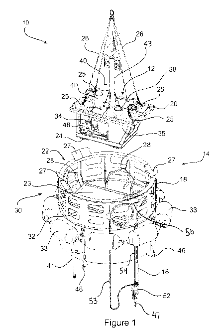
[0034] In Figures 1 to 3, there is shown a support buoy 10 for supporting
subsea equipment
(not shown). The buoy 10 comprises a utilities array 12 contained within a
hull 14. The utilities
array 12 is adapted to provide power and communication services between the
subsea
equipment and the buoy 10. These services are provided by way of an umbilical
16 which is
adapted to transfer such services.
[0035] The hull 14 is provided in two separate components, an outer portion 18
and an inner
portion 20. The outer portion 18 is of a greater diameter than the inner
portion 20. As can be
best seen in Figure 1, the outer portion 18 is substantially cylindrical in
shape with a hollow
interior section 22. The interior has provided therein a cavity 23, adapted to
receive the inner
portion therein, such that the inner portion is substantially contained within
the outer portion 18,
and the outer portion 18 fully surrounds the inner portion 20. Preferably the
outer portion is
filled with foam to aid flotation. An underside of the inner portion 20 is
provided with a series of
bunds 24 to protect the inner portion 20 from impact when being lowered.
[0036] The inner portion 20 is lowered into the outer portion, typically by
way of a crane, and
positioned into the cavity 23. A series of anchor points 25 are provided on a
top side of the inner
portion 18 to allow for the attachments of cables 26 which may be attached to
a crane (not
shown). A series of guidance plates 27 are provided around a perimeter of the
outer portion 18.
These guidance plates 27 are arranged such that the inner portion 18 is guided
towards the
cavity 23 whilst it is lowered into position. Once the inner portion 18 is
fitted into the outer
portion 20, it is retained in that position by a series locking arms 28 which
fold towards the inner
portion 20 to secure its position. Additionally, when the locking arms 28 are
in an open position,
they further act to guide the inner portion 18 towards the cavity 23 as the
inner portion 18 is
lowered into the outer portion 20.
[0037] An upper end 30 of the outer portion 18 is constructed of a light
weight material and
further comprises a number of apertures 32. In the event of impact upon the
buoy 10, the upper
end 30 will deform in order to absorb the energy of the impact, thereby
reducing the shock of
the impact on the remainder of the buoy. Additionally, a series of pneumatic
fenders 33 are
provided around the circumference of the outer portion 20 to further protect
the buoy 10 from
impacts. The utilities array 12 is contained wholly within the inner portion
20.
[0038] The buoy 10 comprises generator unit 34 contained within the hull 14.
The generator
unit 34 is a fuel powered generator capable of providing between 120V and 240V
at continuous
CA 02953155 2016-12-21
WO 2015/196234 PCT/AU2015/000056
7
power. Importantly, the generator unit 34 is capable of being operated at up
to a 30 degree
incline in order to cope with the rocking of the buoy 10 when deployed.
[0039] Fuel for the generator unit 34 is stored in a fuel reservoir 35 which
is contained within the
inner portion 20. The fuel reservoir 35 will typically have a capacity of 250L
and is triple bunded
in order to prevent leakage. The fuel reservoir 35 may be refuelled through a
refuelling point 38
located on the upper side of the inner portion 20. This allows the buoy 10 to
be refuelled
without having to remove the inner portion 20, allowing the refuelling process
to be completed
whilst the buoy 10 is deployed. An air intake and exhaust of the generator
unit 34 are provided
by way of water lock intake and exhaust canisters 40, which are located on the
upper side of the
inner portion 20. The canisters 40 provide an air trap, allowing the buoy to
be submerged and
be operational once it surfaces. These also prevent water getting into the
generator unit 34
during storms or other rough weather conditions. Cooling for the generator
unit 34 is provided
through a water pickup 41 which located on the exterior of the outer portion
18. Operation of
the generator unit 34 is controlled by a number of PLC's (not shown) located
within the utilities
array 12.
[0040] The utilities array 12 further comprises a battery bank 42, which is
charged during
operation of the generator unit 34. The battery bank allows for the operation
of the certain
features of the utilities array 12, without the need for the generator unit 34
to be operating.
[0041] The utilities array 12 is also fitted with additional sensors and data
recording devices (not
shown). These sensors include accelerometers to measure the metocean
conditions and
movement of the buoy 10 during operations. These sensors operate in a feedback
loop with the
PLC's in order to prevent operation of the generator unit during rough ocean
conditions. There
also may be included sensors associated with the generator unit 34, to detect
the temperature
and the fuel status thereof. Data recording devices in the utilities array are
capable of not only
recording data provided by the on board sensors, but are also adapted to
record data recorded
by the subsea equipment.
[0042] The utilities array 12 further comprises a transmissions array (not
shown) which supports
telecommunications and data transmission to and from the buoy 10. The buoy 10
supports
wireless (Wi-Fi), mobile (3G, 4G) and satellite data transmission. An antenna
43 is provided on
an upper surface of the inner portion 20 to support the data transmission of
the transmission
array. The transmission array allows for data from the buoy 10 and the subsea
equipment to be
downloaded remotely from anywhere in the world. It also allows for remote
control of the
generator unit 34 and subsea equipment.
CA 02953155 2016-12-21
WO 2015/196234 PCT/AU2015/000056
8
[0043] The buoy 10 further comprises mooring attachment points 46. The buoy 10
utilises an
established buoy mooring (not shown) to retain the buoy 10 in a desired
location. The buoy
mooring is anchored to a subsea surface in a four point anchor arrangement.
The buoy 10 is
tethered to the mooring by way of the mooring attachments points 46. By
utilising a 3 or 4 point
attachment arrangement, the buoy 10 is prevented from twisting more than 1
degree per metre.
Four anchors (not shown) are provided in a square arrangement 100 metres apart
on the
subsea floor beneath the buoy 10 and are tethered by chains to the mooring
attachments points
46.
[0044] The umbilical 16 is connected to the utilities array 12 by way of a
breakout box (not
shown). If force is appliced to the umbilical 16, the breakout box disconnects
from the utilities
array 12 thereby disconnecting the umbilical 16 from the utilities array 12
without causing
damage.
[0045] The umbilical 16 comprises one or more hybrid cables for both
electricity fibre optics
communications. The umbilical 16 further has triple armouring 47 with a large
breaking load
(for example approximately 440kN) to protect the umbilical and allow for the
retrieval and
deployment of the subsea equipment. The umbilical 16 is adapted to be
disconnected from the
buoy 10 without affecting the seal of the hull 14. It is envisaged that the
umbilical 16 may be
disconnected and dropped to the sea floor to allow the buoy 10 to be
temporarily moved to
another location.
[0046] As best shown in Figures 1 and 3, the umbilical 16 is fed through an
umbilical strain
terminator 52, which progressively removes the triple armouring 47 from the
umbilical 16 to
expose the one or more hybrid cables. The umbilical strain terminator 52 also
provides an
anchoring point to allow the deployment of the umbilical 16. A deployment
chain 53 attaches to
the umbilical strain terminator 52 which can then be in turn attached to a
crane, or other whinch,
to lift the umbilical 16. Also attached to the umbilical strain terminator 52
is a break point chain
54. If the strain on the umbilical 16 is too high, for example during a
storm or in the event of a
watercraft collision, the break point chain 54 will break, triggering the
disconnection of the
umbilical strain terminator 52 from the buoy 10The umbilical is fed through a
cutting point 56,
such that if the umbilical strain terminator 52 is detached form the buoy 10,
then the strain
applied on the umbical 16 will cause the cutting of the umbical 16 at the
cutting point 56.
[0047] Advantageously, the buoy 10 of the present invention is able to provide
support services
to subsea equipment located in offshore locations. This allows for the subsea
equipment to be
operated without the need of a support ship and crew to be on location for an
extended period
of time. Particularly, this allows for the subsea equipment to collect data
for a far greater period
CA 02953155 2016-12-21
WO 2015/196234 PCT/AU2015/000056
9
of time. The utilities array 12 can also be arranged such that the generator
unit 34 may be
started automatically at set intervals. Additionally, by being able to drop
the umbilical 16, the
buoy 10 of the present invention can be moved from one piece of subsea
equipment to another
without the need to retrieve the first piece of equipment.
[0048] Due to its design, the buoy 10 can withstand impacts and can withstand
cyclones with
the ability to be submerged for short periods. With the inclusion of the
inbuilt accelerometers,
the generator unit 34 will automatically stop operation if rough conditions
are experienced by the
buoy 10. In the event that the buoy 10 becomes caught up in a vessel, the
umbilical 16 has a
controlled break point, meaning that the buoy 10 will not be dragged with the
vessel.
[0049] Those skilled in the art will appreciate that the invention described
herein is susceptible
to variations and modifications other than those specifically described. The
invention includes
all such variation and modifications. The invention also includes all of the
steps, features,
formulations and compounds referred to or indicated in the specification,
individually or
collectively and any and all combinations or any two or more of the steps or
features.