Note : Les descriptions sont présentées dans la langue officielle dans laquelle elles ont été soumises.
CA 02953660 2016-12-23
WO 2015/199696
PCT/US2014/044319
METHODS FOR MANUFACTURING ENCAPSULATED GRANULAR
MATERIAL, METHODS FOR DRYING COATING MATERIALS, AND
FLUIDIZED BED DRYERS
Technical Field
The present invention relates to methods for manufacturing encapsulated
granular material, methods for drying coating materials, and fluidized bed
dryers.
Background
Seamless capsules in which medicines are encapsulated in capsules without a
seam have been used in recent years for medical and pharmaceutical products
and the
like (for example, refer to Patent Document 1). Such seamless capsules are
formed,
for example, by encapsulating the contents with a coating material containing
water
using a falling-drop method utilizing a multiplex nozzle and drying the
coating
materials. In the falling-drop method, a double nozzle which includes an inner
discharge port for discharging contents to fill the inside of capsules and an
outer
discharge port for coating materials surrounding the inner discharge port is
used for
example when manufacturing two-layered capsules. By simultaneously dripping
the
contents and water-soluble coating materials such as gelatin respectively from
the
inner discharge port and outer discharge port, the coating materials surround
the outer
boundary of the contents and become spherical due to surface tension. By
dripping
these droplets into auxiliary gelation agents, cooling oil, or the like, the
coating
materials can be solidified while surrounding the content, by taking advantage
of
gelation and/or solidification due to cooling.
Seamless capsules can be formed for example by blow-drying the solidified
coating materials using a rotary drum-type through-flow dryer or a fluidized
bed dryer
(for example, refer to Patent Document 1 Paragraph 110039]).
Prior Art Documents
Patent documents
Patent Document 1: Japanese Patent No. 4,051,075
1
CA 02953660 2016-12-23
WO 2015/199696
PCT/US2014/044319
Summary of the Invention
Problems to be Solved by the Invention
As indicated with arrows in Figure 8, part of the supply of drying air passes
through between a case 102 and a basket 104 in a rotary drum-type through-flow
dryer 101, and the proportion of the drying air that passes through the basket
104 is
low. Therefore, the drying efficiency is very low.
In contrast, when a fluidized bed dryer is used, all of the drying air passes
through the drying room accommodating the capsules, and therefore the drying
efficiency is high. Nevertheless, even when a fluidized bed dryer is used, the
drying
time is still long, and thus a reduction in the drying time is desired. One
possible way
to decrease the drying time would be to supply a large amount of drying air of
high
temperature in a temperature range that would not melt coating materials and
would
provide low humidity. However, if such drying air of high temperature and low
humidity is supplied in a large amount, drying proceeds too rapidly and
deformation
of the coating of the seamless capsules may occur.
The present invention was made in light of the problems discussed above, and
is intended to shorten the drying time for drying seamless capsules without
causing
deformation of the coating when drying encapsulated granular material that is
encapsulated with water-containing coating materials such as gelatin in the
form of a
seamless capsule and using a fluidized bed dryer.
Means for Solving the Problem
The method for manufacturing the encapsulated granular material of the
present invention is directed to a method for manufacturing an encapsulated
granular
material whose contents are encapsulated with coating. The method comprises a
step
of creating encapsulated material by encapsulating the contents with a coating
material that contains water and forms a coating when the water content of the
coating
material is decreased. The method comprises a further step of drying the
coating
material of the encapsulated material by floating and fluidizing the
encapsulated
material using a fluidized bed dryer. The step of drying the coating materials
comprises a first drying step of floating and fluidizing the encapsulated
material using
a fluidized bed dryer while measuring the water content or temperature of gas
exhausted from the dryer after floating and fluidizing the encapsulated
material; and a
second drying step of blowing gas into the dryer while the operating
conditions of the
2
CA 02953660 2016-12-23
WO 2015/199696
PCT/US2014/044319
fluidized bed dryer are set so that the theorisable evaporating water content
AW rises
above that which was present during the first drying step. The second drying
step is
performed after the measured water content is reduced below a prescribed
amount or
the measured temperature is increased.
The method for drying coating materials of the present invention is a method
for drying coating materials of an encapsulated material whose contents are
encapsulated with coating materials that contain water and form a coating when
the
water content decreases. The drying step is carried out by floating and
fluidizing a
number of items of encapsulated material using a fluidized bed dryer. The
method
comprises a first drying step of floating and fluidizing a number of items of
encapsulated material while measuring the water content or temperature of gas
exhausted after floating and fluidizing the encapsulated material using a
fluidized bed
dryer. The second drying step comprises blowing gas into the dryer while the
operating conditions of the fluidized bed dryer are set so that the
theorisable
evaporating water content AW rises above that which was presented during the
first
drying step. The second drying step is performed after the measured water
content
measured is reduced below a prescribed amount or the measured temperature has
increased.
According to the present invention, a shift from a constant-rate drying phase
to
a decreasing-rate drying phase can be identified by measuring the water
content or
temperature of gas exhausted after floating and fluidizing the encapsulated
material
using a fluidized bed dryer. Thereby, the drying time of a decreasing-rate
drying
phase can be shortened, by controlling a drying air supplying apparatus so
that the
theorisable evaporating water content AW rises after the measured water
content is
reduced below a prescribed amount or the measured temperature is increased,
i.e.,
after the shift to a decreasing-rate drying phase. Even if the drying ability
of drying
air is increased in this manner, deformation of the coating material will not
occur
because the amount of water evaporating from the coating material is small
during the
decreasing-rate drying phase.
Preferably, in the method described above, gas blowing by a fluidized bed
dryer is controlled during the first drying step so that AW/Sa, the ratio of
theorisable
evaporating water content AW of the gas blown in by the fluidized bed dryer to
the
total surface area Sa of the encapsulated material, is 10 or below.
3
CA 02953660 2016-12-23
WO 2015/199696
PCT/US2014/044319
Preferably, in the method above, gas blowing by a fluidized bed dryer is
controlled during the first drying step so that AW/Sa, the ratio of
theorisable
evaporating water content AW of the gas blown in by the fluidized bed dryer to
the
total surface area Sa of the encapsulated material, is 7 or below.
According to the present invention of the configurations described above,
coating materials can be dried using drying air with a maximized or maximum
drying
ability in a manner that will not cause deformation of the capsule coating
during a
constant-rate drying phase, and, as a result, the coating materials can be
dried in a
shorter time.
Preferably, in the method above, the theorisable evaporating water content
AW is calculated based on the product of:
the difference between;
an amount of water vapor per unit weight contained in the gas used for
floating and fluidizing the encapsulated material calculated from temperature
te and
the relative humidity Re of the gas before blowing; and
an amount of saturated water vapor per unit weight that can be
contained in the gas exhausted after floating and fluidizing the encapsulated
material
calculated from the temperature of the exhausted gas, the temperature te and
the
relative humidity Re of gas before blowing; and
the weight of the gas used for floating and fluidizing the encapsulated
material
per unit time.
Preferably, in the method described above, the encapsulated granular material
is a soft capsule.
Preferably, in the method described above, the encapsulated granular material
is a seamless capsule.
Preferably, in the method described above, at least one of the following is
performed during the second drying step: raising the temperature of the gas
used for
floating and fluidizing the encapsulated material to a temperature higher than
that
used during the first drying step; reducing the humidity of the gas used for
floating
and fluidizing the encapsulated material to a lower humidity than that used
during the
first drying step; and increasing the volume of gas used for floating and
fluidizing the
encapsulated material to a higher volume than the volume used during the first
drying
step.
4
CA 02953660 2016-12-23
WO 2015/199696
PCT/US2014/044319
The fluidized bed dryer of the present invention is a fluidized bed dryer for
drying coating materials of encapsulated material whose contents are
encapsulated in
coating materials that contain water and form a coating when the water content
decreases. The fluidized bed dryer comprises a measuring means or apparatus
for
measuring a water content or temperature of gas exhausted after floating and
fluidizing the encapsulated material using the fluidized bed dryer; and a
control
means or apparatus, e.g. a controller for controlling at least one of the
temperature,
humidity and volume of gas blown to the encapsulated material in the fluidized
bed
dryer based on the water content measured by the measuring means. The control
means alters at least one of the temperature, humidity and volume of the gas
to be
blown when the measured water content is reduced below a prescribed amount or
the
measured temperature is increased, so that the theorisable evaporating water
content
AW increases when the gas to be blown to the encapsulated material is blown to
encapsulated material in the initial drying state.
Preferably, in the fluidized bed dryer described above, the control means
controls at least one of the temperature, humidity and volume of the gas blown
to the
encapsulated material, so that AW/Sa, the ratio of the theorisable evaporating
water
content AW of the gas blown in by the fluidized bed dryer to the total surface
area Sa
of the encapsulated material, is 10 or below, before altering at least one of
the
temperature, humidity and volume of the gas so that the amount of water
evaporation
from the coating materials increases.
Preferably, in the fluidized bed dryer described above, the control means
controls at least one of the temperature, humidity and volume of the gas blown
to the
encapsulated material, so that AW/Sa, the ratio of the theorisable evaporating
water
content AW of the gas blown in by the fluidized bed dryer to the total surface
area Sa
of the encapsulated material, is 7 or below, before altering at least one of
the
temperature, humidity and volume of the gas so that the amount of water
evaporation
from the coating materials increases.
Preferably, in the fluidized bed dryer described above, the theorisable
evaporating water content AW is calculated based on the product of:
the difference between;
an amount of water vapor per unit weight contained in the gas used for
floating and fluidizing the encapsulated material calculated from the
temperature te
and the relative humidity Re of the gas before blowing; and
CA 02953660 2016-12-23
WO 2015/199696
PCT/US2014/044319
an amount of saturated water vapor per unit weight that can be
contained in the gas exhausted after floating and fluidizing the encapsulated
material
in the fluidized bed dryer calculated from the temperature of the exhausted
gas and
from the temperature t., and the relative humidity Re of the gas before
blowing; and
the weight of the gas used for floating and fluidizing the encapsulated
material
per unit time.
Preferably, in the fluidized bed dryer described above, the encapsulated
granular material is a soft capsule.
Preferably, in the fluidized bed dryer method described above, the
encapsulated granular material is a seamless capsule.
Effects of the Invention
The drying time using a fluidized bed dryer for drying an encapsulated
granular material whose outer boundary is encapsulated with water-soluble
substances
such as gelatin can be shortened due to the present invention.
Brief Explanation of the Drawings
Figure 1 is a cross-sectional view showing the structure of a seamless capsule
manufactured by the manufacturing method of the present embodiment.
Figure 2 is a diagram showing a double nozzle for encapsulating contents with
coating materials.
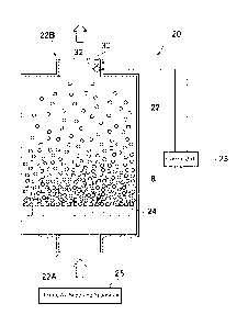
Figure 3 is a diagram showing the structure of a fluidized bed dryer which
may be used in the present invention.
Figure 4 is a graph showing the water content (relative humidity) and
temperature of the exhaust air exhausted when accommodating encapsulated
material
in the drying room and supplying drying air while keeping the temperature,
humidity
and air volume constant using the control unit in the fluidized bed dryer of
Figure 3.
Figure 5 shows a psychrometric chart.
Figure 6 is a photograph showing seamless capsules post drying of Condition
1.
Figure 7 is a photograph showing seamless capsules post drying of Condition
5.
Figure 8 is a diagram showing a rotary-drum type through-flow dryer.
6
CA 02953660 2016-12-23
WO 2015/199696
PCT/US2014/044319
Modes for Carrying out the Invention:
An embodiment of the method for manufacturing encapsulated granular
material of the present invention is explained below in detail, while
referring to the
drawings.
Figure 1 is a cross-sectional view showing the structure of a seamless capsule
manufactured by the manufacturing method of the present invention. As shown in
the
figure, a seamless capsule 1 manufactured by the manufacturing method of the
present invention has a two-layer structure formed by a content 2 whose outer
boundary is encapsulated with seamless coating 4.
Examples for the content 2 include medical and pharmaceutical products,
quasi-drugs, cosmetics, functional foods, health foods, general foods,
chemical
products, and the like. The contents are not limited to liquids such as
lipophilic liquids,
hydrophilic liquids, and surfactants, and thus the present invention can be
applied
even for solids, microcapsules, gels and the like, the present invention can
be applied
by liquefying the solids, microcapsules, gels and the like by heat-melting or
by
suspending or dispersing the materials in a liquid or emulsifying them.
Examples for lipophilic liquids include a combination of vitamin E and a
medium-chain fatty acid triglyceride in which the vitamin E is dissolved, and
the like.
Examples of hydrophilic substances include, for example, combinations of
ingredients
of rhinitis medications, mequitazine, belladonna alkaloid, and anhydrous
caffeine, and
a medium-chain fatty acid triglyceride oil that functions as a dispersion
medium.
Hydrophilic substances may also be made suitable for use as the contents 2 by
dissolving the hydrophilic substances in one or more polyethylene glycols,
which are
hydrophilic oily substances. Examples of suitable surfactants include lecithin
and the
like, and such surfactants may be used as the contents 2 as they are or by
dissolving or
emulsifying them in oily substances.
Coating 4 is formed by drying a coating material containing water. As used
herein, "coating material" refers collectively to the combination of
components that
forms the precursor material that forms a coating when dried to remove water.
For
example, gelatinizers such as gelatin, agar, alginate, carrageenan, pectin,
and gums
such as guar gum, xanthan gum, gum arabic, gellan gum, locust bean gum,
tamarind
gum, and the like, may be used as coating materials. Coating forming agents
such as
starch, cellulose, polyvinyl alcohol, and the like that are conventionally
used together
with the above-mentioned gelatinizers may also be used as part of coating 4.
7
CA 02953660 2016-12-23
WO 2015/199696
PCT/US2014/044319
The gelatinizers may be gelled by use of auxiliary gelation agents such as
potassium ions, sodium ions, calcium ions, and ammonium ions.
Such seamless capsules are manufactured as described below.
Figure 2 is a diagram showing a double nozzle for encapsulating contents with
coating materials. As shown in the figure, a double nozzle 10 comprises an
outer
nozzle 14 from which a coating material 6 is supplied; an inner nozzle 12 from
which
contents placed on the inward side of the outer nozzle 14 are supplied; and a
vibrator
16 which applies vibrations to the outer nozzle 14 and inner nozzle 12. The
tip of the
double nozzle 10 is immersed in a container or a liquid flow pipe (in the
presently
depicted embodiment, a liquid flow pipe) 19 filled with solidifying liquid or
cooling
oil (referred to below as "solidifying liquid") 18. By applying vibration from
the
vibrator 16 to the inner nozzle 12 and outer nozzle 14 or pipes, tubes, or the
solidifying liquid 18 that are connected to the double nozzle 10 while a
content 2 and
the coating material 6 are supplied in the inner nozzle 12 and the outer
nozzle 14
respectively, the content 2 and the coating material 6 are dripped from the
inner
nozzle 12 and the outer nozzle 14 respectively. The dripped coating material 6
then
surrounds the outer boundary of the content 2 due to the surface tension.
Encapsulated
material 8 in which the outer boundary of the content 2 is encapsulated in
this manner
with the coating material 6 is continuously dripped into the liquid flow pipe
19 filled
with the solidifying material 18. By being dripped into the solidifying liquid
18, the
encapsulated material 8 solidifies while the content is enclosed in the
coating material
6. Auxiliary gelation agents such as potassium ions, sodium ions, calcium
ions, and
ammonium ions may be used as component(s) of such a solidifying liquid.
Subsequently, the encapsulated material 8 manufactured in this manner is
located in a fluidized bed dryer, and the coating material 6 that surrounds
the content
2 is dried. Figure 3 is a diagram showing the structure of a fluidized bed
dryer used in
the present embodiment. As shown in the figure, the fluidized bed dryer 20
comprises
an exterior case 22 and a straightening board 24 that regulates the flow of
drying air
placed in the lower part inside the exterior case 22. An inlet 22A into which
drying air
flows is formed at the bottom of the exterior case 22, and an outlet 22B for
exhausting
air that has passed through the exterior case 22 (drying room) is formed at
the top of
exterior case 22.
The fluidized bed dryer 20 further comprises a drying air supplying apparatus
26, a temperature sensor 30 and a humidity sensor 32 attached at the outlet
22B on the
8
CA 02953660 2016-12-23
WO 2015/199696
PCT/US2014/044319
exterior case 22, and a control unit 28 that controls the operation of the
drying air
supplying apparatus 26. The drying air supplying apparatus 26 is connected to
the
control unit 28, and the temperature, humidity and flow rate of drying air
blown from
the drying air supplying apparatus 26 to the encapsulated material 8 located
in the
exterior case 22 may be set through use of the control unit 28.
The drying air supplying apparatus 26 is connected to the inlet 22A of the
exterior case 22 and supplies drying air into the exterior case 22. Drying air
supplied
from the drying air supplying apparatus 26 passes through the inside of the
exterior
case 22 and is exhausted from the outlet 22B. As a result, the coating
material 6 may
be dried as the encapsulated material 8 located in the exterior case 22 is
floated and
fluidized by the drying air.
The temperature sensor 30 and humidity sensor 32, respectively, measure the
temperature and humidity of the exhaust air exhausted from the exterior case
22. The
temperature sensor 30 and humidity sensor 32 are connected to the control unit
28,
and the measured temperature and humidity of the exhaust air are transmitted
to the
control unit 28.
Here, the present inventors conceived that one of the causes of deformation of
coating materials that occurs while drying the coating materials is a
reduction in the
volume associated with rapid water release from the coating materials.
Therefore, the
present inventors examined methods for preventing deformation of coatings by
preventing rapid water release from the coating materials, as explained below.
First, the inventors conceived that rapid water release from the coating
materials may be prevented by altering the temperature, humidity and flow rate
of
drying air according to the drying time when drying coating materials.
Figure 4 is a graph showing the water content (relative humidity) and
temperature of the exhaust air exhausted when the encapsulated material 8 is
located
in the exterior case 22 and drying air is supplied while keeping the
temperature,
humidity and volume constant through the control unit 28 in the fluidized bed
dryer
shown in Figure 3. As shown in the figure, the humidity of exhaust air (solid
line) is
roughly 100% until a given time period has passed from when drying started,
but the
humidity of the exhaust air decreases over time after a certain length of
drying time.
The temperature of the exhaust air (dashed line) is constant at a low level
(wet-bulb
temperature) for a given time length from when drying starts but increases
over time
after the drying time has passed beyond a certain point. The time period from
when
9
CA 02953660 2016-12-23
WO 2015/199696
PCT/US2014/044319
drying started to when the humidity of exhaust air starts decreasing or the
temperature
of the exhaust air starts increasing is called the constant-rate drying phase,
and the
period after the time when the humidity of the exhaust air starts decreasing
or the
temperature of the exhaust air starts increasing is called the decreasing-rate
drying
phase.
During the constant-rate drying phase, the amount of water that migrates
within the coating materials is large enough so that the equilibration state,
in which
water keeps evaporating from the coating materials until the humidity of the
drying
air reaches 100%, continues and the humidity of the exhaust air remains
constant. The
temperature of the exhaust air will be the wet-bulb temperature, the
temperature of the
drying air less the temperature component corresponding to the latent heat of
evaporation.
In contrast, during the decreasing-rate drying phase, the amount of water that
migrates within the coating materials decreases, and therefore the amount of
water
evaporating from the coating surface decreases, the humidity of the exhaust
air
decreases, and the temperature and humidity of the exhaust air begin to
approach the
temperature and humidity of the supplied drying air.
The present inventors originally used to carry out drying with a constant
drying ability throughout the constant-rate drying phase and the decreasing-
rate
drying phase. However, the amount of water evaporating from coating materials
per
given time during the decreasing-rate drying phase is much smaller than the
amount
of water evaporating from coating materials per given time during the constant-
rate
drying phase. In the decreasing-rate drying phase, as the amount of water
evaporating
from the coating surface is decreasing, most of the water has evaporated, and
the
volume has shrunk nearly to the volume at the drying end point. Hence, the
present
inventors conceived that deformation of seamless capsules will not occur even
if the
drying ability of the drying air is raised as in the present invention and
that the drying
time can be shortened by raising the drying ability of drying air during the
decreasing-
rate drying phase to a drying ability that is higher than the drying ability
of the drying
air during the constant-rate drying phase.
Accordingly, using the ratio of the theorisable evaporating water content per
unit time AW of drying air to the total surface area Sa of the capsules as an
index
indicating the amount of water evaporating from the coating materials per unit
time,
the inventors adjusted the temperature, humidity, and volume of the drying air
so that
CA 02953660 2016-12-23
WO 2015/199696
PCT/US2014/044319
the ratio of the theorisable evaporating water content per unit time AW of
drying air
to the total surface area Sa of the capsules during the constant-rate drying
phase is
kept at a fixed value or below and the ratio of the theoris able evaporating
water
content per unit time AW of drying air to the total surface area Sa of the
capsules
during the decreasing-rate drying phase is larger than the ratio of the
theorisable
evaporating water content per unit time AW of drying air to the total surface
area Sa
of capsules during the constant-rate drying phase.
The inventors decided to divide (theorisable evaporating water content per
unit time AW of drying air) by (total surface area Sa of capsules),
considering that the
drying speed of the coating of each capsule has a higher degree of correlation
with the
surface area of a capsule, which is the evaporation surface, than with the
capsule
weight (the total water amount to be vaporized). Here, the total surface area
Sa of the
capsules is the total surface area in the initial drying state, since the
number of
capsules in both the constant-rate drying phase and the decreasing-rate drying
phase
does not change and can be considered constant.
The theorisable evaporating water content AW herein is the maximum amount
of water that can be contained in drying air per unit time, which can be
calculated as
below.
First, saturated water vapor pressure E at temperature t is calculated using
the
formula 1 below.
E = 6.11 * 1 0 (7.5 Inti( 237 .3+t))
Formula 1
Partial water vapor pressure Ep may be calculated using the formula 2 below.
Ep = E * RH I 100
Formula 2
Specific humidity H (kg/kgDA) may be calculated using the formula 3 below,
wherein P (Pa) is atmospheric pressure.
H = 18/29 * Ep l(P - Ep)
Formula 3
11
CA 02953660 2016-12-23
WO 2015/199696
PCT/US2014/044319
Thus, the specific humidity of the drying air Ho may be calculated using the
formula 4 below, wherein the temperature and relative humidity of drying air
are te
( C) and Re (%), respectively, and the atmospheric pressure is 1013.25 Pa.
1/0 = 18/29*6.11*10(7.5*tc1(237 .3+tc))*R /100/
c
(1013.25-6.11*10(7.5*tc1(237 .3+tc))*Rc/100)
Formula 4
Air is able to contain water until the relative humidity is 100%. Therefore,
the
maximum value of the relative humidity of the exhaust air is 100%. The
temperature
of the drying air decreases due to latent heat as the humidity increases. Tw,
the
temperature of such exhaust air whose relative humidity is 100%, may be
calculated,
for example, by using the psychrometric chart in Figure 5 or an approximate
expression based on a psychrometric chart. For example, if drying air having a
temperature of 26 C and a relative humidity of 35% RH (Point A in Figure 5)
incorporates water vapor until the relative humidity reaches 100%, the
temperature of
the exhaust air (Point B in Figure 5) will be 16 C. Alternatively, the
temperature of
the exhaust air may be calculated based on latent heat which may be calculated
based
on the water content of drying air.
Specific humidity of saturated exhaust air Hw may be calculated using the
formula 5 below.
Hw = 18/29*6.11*10(7.5*tw/(237.3 tw))* 1 00/ 1 00/
(1013.25-6.11*10(7.5*tw1(237 .3+tw))*1001100)
Formula 5
The weight of drying air as dry air GO may be calculated as in the formula 6
below, using the volume Vc and the humid volume Vh of drying air at a
temperature
Tc C and a relative humidity Rc%:
GO =Vc / Vh = Vc /(22.4 x (1/ 29 + lic /18) x (273 + Tc)/ 273)
Formula 6
12
CA 02953660 2016-12-23
WO 2015/199696
PCT/US2014/044319
Thus, the amount of water that can be contained in drying air per minute when
the flow rate of drying air is V (m3/min), i.e., the theorisable evaporating
water
content per unit time AW, is the difference between the amount of water vapor
per
unit volume of the gas used for floating and fluidizing the encapsulated
material
before blowing and the amount of saturated water vapor that can be contained
per unit
volume of gas exhausted after floating and fluidizing the encapsulated
material, which
is calculated by the formula 7 below.
AW = (Hw ¨ H o)* GO
Formula 7
Furthermore, the present inventors conceived that the drying time can also be
shortened in the constant-rate drying phase by adjusting the theorisable
evaporating
water content AW, while preventing deformation. Here, the inventors expected
that
deformation of capsules would occur when AW/Sa, the theorisable evaporating
water
content per unit time per unit area of capsules, is high, and conducted the
experiments
described below using the theorisable evaporating water content AW/Sa as an
index.
In these experiments, gelatin with glycerin and sorbitol plasticizers, was
used
as the coating material, and a medium-chain fatty acid triglyceride was used
as the
content. Encapsulated material was created by dripping the content
encapsulated in
gelatin into cooling oil.
In these experiments, seamless capsules were manufactured using a fluidized
bed dryer under Conditions 1-12, in which the total surface area Sa of
capsules
located in a fluidized bed dryer, the temperature te of drying air during the
constant-
rate drying phase and decreasing-rate drying phase, the relative humidity Re
of the
drying air, and the flow rate V of the drying air were varied. Table 1 shows
the total
surface area Sa of capsules, the temperature te of the drying air during the
constant-
rate drying phase and decreasing-rate drying phase, the relative humidity Re
of the
drying air, and the flow rate V of the drying air under the Conditions 1-12.
13
CA 02953660 2016-12-23
WO 2015/199696 PCT/US2014/044319
Tablet
Condition No.: 1 2 3 4 5 6
capsules total number of 15700 15700 27000 40000 40000 40000
capsules N
total weight M (kg) 0.890 0.890 1.553 2.300 2.300
2.300
total surface area 1.044 1.044 1.795 2.659 2.659 2.659
Sa (m2)
total water content 0.435 0.435 0.748 1.108 1.108
1.108
W (kg)
drying drying air 26 26 26 35 26 26
air temperature tc ( C)
(constant drying air relative 8.5 35 8.5 22 35 35
-rate humidity Rc
drying (%RH)
phase) specific humidity 0.0018 0.0073 0.0018 0.0077 0.0073 0.0073
Ho (kgH20/kgDA)
exhaust air 10.7 16 10.7 19.5 16 16
temperature tw
( C)
exhaust air 0.008 0.011
0.008 0.014 0.011 0.011
saturated water
vapor content
(kgH20/kgDA)
air volume V 3.499 3.499 2.651 2.651 4.135 3.499
(m3/min)
theorisable 0.026 0.017
0.019 0.020 0.020 0.017
evaporating water
content AW (H20
kg/min)
drying time (hr) 0.200 0.330 0.580 0.550 0.420
1.250
AW/S a (H20 24.621 15.870 10.846 7.384
7.361 6.229
g/(m2.min))
drying drying air 26 26 26 35 26 26
air temperature tc ( C)
(decreasi drying air relative 8.5 35 8.5 22 35 8.5
ng-rate humidity (%RH)
drying air volume V 3.499 3.499 2.651 2.651 4.135 3.499
phase) (m3/min)
drying time (hr) 2.50 4.90 3.42 2.70 4.58 4.00
total 2.70 5.20 4.00 3.25 5.00 5.25
drying
time (hr)
14
CA 02953660 2016-12-23
WO 2015/199696 PCT/US2014/044319
Table 1 (continued)
Condition No.: 7 8 9 10 11 12
capsules total number of 40000 40000 40000 40000 40000 80000
capsules N
total weight M (kg) 2.300 2.300 2.300 2.300 2.300 2.300
total surface area 2.659 2.659 2.659 2.659 2.659 5.318
Sa (m2)
total water content 1.108 1.108 1.108 1.108 1.108 2.216
W (kg)
drying drying air 26 26 26 26 26 26
air temperature tc ( C)
(constant drying air relative 35 35 35 35 35 35
-rate humidity Rc
drying (%RH)
phase) specific humidity 0.007 0.007 0.007 0.007 0.007 0.007
Ho (kgH20/kgDA)
exhaust air 16 16 16 16 16 16
temperature tw
( C)
exhaust air 0.011 0.011
0.011 0.011 0.011 0.011
saturated water
vapor content
(kgH20/kgDA)
air volume V 3.499 2.651 2.651 2.651 1.590 2.651
(m3/min)
theorisable 0.017 0.013 0.013 0.013 0.008 0.013
evaporating water
content AW (H20
kg/min)
drying time (hr) 1.330 1.200 1.160 1.000 1.670 2.170
AW/Sa (H20 6.229 4.719 4.719 4.719 2.831 2.359
g/(m2.min))
drying drying air 26 26 35 35 26 35
air temperature tc ( C)
(decreasi drying air relative 35 35 22 22 35 22
ng-rate humidity (%RH)
drying air volume V 3.499 2.651 2.651 2.651 1.590 2.651
phase) (m3/min)
drying time (hr) 4.87 5.60 3.59 2.80 5.33 2.83
total 6.20 6.80 4.75 3.80 7.00 5.00
drying
time (hr)
As shown in Table 1, under Conditions 9, 10, and 12, the temperature of the
drying
air during the decreasing-rate drying phase is higher than the temperature
during the constant-
rate drying phase, and the relative humidity of drying air during the
decreasing-rate drying
phase is lower than the relative humidity during the constant-rate drying
phase. Therefore, the
theorisable evaporating water content per unit time AW of the drying air
during the
decreasing-rate drying phase when applied to encapsulated material in the
initial drying state
is higher than AW of the drying air during the constant-rate drying phase
under Conditions 9,
CA 02953660 2016-12-23
WO 2015/199696 PCT/US2014/044319
10, and 12. The theorisable evaporating water content per unit time AW/Sa of
the drying air
during the decreasing-rate drying phase when applied to encapsulated material
in the initial
drying state under Conditions 9, 10, and 12 was equal to the AW/Sa during the
constant-rate
drying phase under Condition 4, which was 7.3844.
Table 2 shows whether deformation such as dimples occurred on the surface of
capsules under Conditions 1-12.
Table 2
Condition No.: 1 2 3 4 5 6
quality post dimples or large large large slight
slight none
drying deformation
out of roundness - 0.981
Condition No.: 7 8 9 10 11 12
quality post dimple or none none none none none none
drying deformation
out of roundness 0.98 0.978 0.983 0.978
0.983
As shown in Table 2, large dimples or deformations occurred on the surface of
seamless capsules under Conditions 1-3. Figure 6 is a photograph showing
seamless capsules
post drying under Condition 1. As shown in figure 6, deformation occurred and
the spherical
shape was lost.
Under Conditions 4-5, dimples were generated on the surface of seamless
capsules.
Figure 7 is a photograph showing seamless capsules post drying of Condition 5.
As shown in
the figure, slight dimples that would not cause issues when using are
generated, while the
spherical shape is not lost.
On the other hand, no dimples or deformation occurred on the surface of the
seamless
capsules made under Conditions 6-12.
According to these results, large dimples or deformations in seamless capsules
can be
prevented by keeping AW/Sa during the constant-rate drying phase at 10 or
below, and
seamless capsules without any dimples or deformation can be manufactured by
keeping
AW/S a during the constant-rate drying phase at 7 or below.
In Condition 4, the drying ability remained unchanged during the constant-rate
drying
phase and decreasing-rate drying phase, and the AW/Sa for the seamless
capsules in the initial
drying state was 7.3844. Slight dimples were generated on seamless capsules
under Condition
4.
In contrast, under Conditions 9, 10, and 12, the AW/Sa for the seamless
capsules in
the initial drying state was, respectively, 4.7188; 4.7188; and 2.3594 during
the constant-rate
drying phase, and the AW/Sa for the seamless capsules in the initial drying
state was changed
16
CA 02953660 2016-12-23
WO 2015/199696
PCT/US2014/044319
to 7.3844 during the decreasing-rate drying phase. No deformation or dimples
occurred on the
surface of the seamless capsules manufactured under Conditions 9, 10, and 12.
According to these results, the drying time of a decreasing-rate drying phase
can be
shortened and the coating can be dried in a short time as a whole without
causing deformation,
by increasing the drying ability of drying air during the decreasing-rate
drying phase to a
drying ability that is higher than the drying ability during the constant-rate
drying phase.
Based on the experimental results, the coating material 6 of the encapsulated
material
8 is dried in a manner explained below in the present embodiment. Drying is
carried out while
measuring the temperature and humidity of the exhaust air exhausted from the
exterior case
22 using the temperature sensor 30 and the humidity sensor 32.
First, control unit 28 controls the drying air supplying apparatus 26 so that
drying air
is blown in at a pre-set temperature, relative humidity, and air velocity.
Preferably, the
temperature, relative humidity, and air velocity of the drying air are set so
that AW/S a
calculated as above is 10 or below, and more preferably, the temperature,
relative humidity,
and air velocity of the drying air are set so that AW/S a is 7 or below. The
coating material 6 is
then dried while floating and fluidizing the encapsulated material by blowing
drying air into
the exterior case 22, while keeping the temperature, relative humidity, and
air velocity
constant (the first drying step). This first drying step corresponds to the
constant-rate drying
phase and the early stage of the decreasing-rate drying phase for the coating
material 6.
Second, after detecting that the humidity of the exhaust air measured by the
humidity
sensor 32 is reduced to or below a prescribed humidity level (for example,
60%), the control
unit 28 controls the operating conditions of the drying air supply apparatus
26 so that the
drying ability of drying air increases. Specifically, the control unit 28
blows drying air at a
temperature, relative humidity, and air velocity that are set so that AW/S a
(here, substantially
AW, since Sa is constant) increases (the second drying step). This drying step
corresponds to
the middle and later stages of the decreasing-rate drying phase for the
coating material 6.
Drying air is supplied until the proportion of water in the coating material 6
reaches a set
point without altering the temperature, relative humidity and air velocity.
Through the processes above, the coating material 6 is dried and the seamless
capsule
1 may be manufactured.
As explained above, once the humidity of the exhaust air measured by the
humidity
sensor 32 is detected to be reduced to or below a prescribed humidity level,
the drying air
supplying apparatus 26 is controlled so that the drying ability of drying air
increases, i.e., so
that the theorisable evaporating water content AW of the drying air when
floating and
fluidizing the encapsulated material 8 of the initial drying state increases.
Thereby, the drying
time of the decreasing-rate drying phase can be shortened. Even if the drying
ability of the
drying air is raised in this manner, deformation of the coating material 6
does not occur
17
CA 02953660 2016-12-23
WO 2015/199696
PCT/US2014/044319
because the amount of water evaporating from the coating material 6 is small
during a
decreasing-rate drying phase.
Furthermore, the control unit 28 controls the drying air supplying apparatus
26 so that
AW/S a is preferably 10 or below and more preferably 7 or below during the
first drying step
(i.e., constant-rate drying phase). Therefore, the coating material 6 can be
dried using drying
air with the maximum drying ability that will not cause deformation during a
constant-rate
drying phase, and the coating material 6 can be dried in a shorter time.
In the embodiment above, once the humidity of the exhaust air measured by the
humidity sensor 32 was detected to be reduced to or below a prescribed
humidity level, the
control was carried out so that the drying ability of drying air increases.
Alternatively, the
control may be carried out so that the drying ability of drying air increases
once the
temperature of exhaust air measured by the temperature sensor 30 is detected
to be raised to
or above a prescribed temperature. Similar effects will be provided by such a
configuration.
Explanation of Symbols
1 seamless capsule
2 content
4 coating
6 coating material
8 encapsulated material
double nozzle
12 inner nozzle
14 outer nozzle
16 vibrator
18 solidifying material
19 container
fluidized bed dryer
22 exterior case
24 straightening board
26 drying air supplying apparatus
28 control unit
temperature sensor
32 humidity sensor
18