Note : Les descriptions sont présentées dans la langue officielle dans laquelle elles ont été soumises.
CA 02955049 2017-01-12
WO 2016/014626 PCT/US2015/041471
FLEXIBLE TUBE CLEANING LANCE POSITIONER FRAME
APPARATUS
BACKGROUND OF THE DISCLOSURE
[0001] The present disclosure is directed to high pressure fluid rotary nozzle
systems. In particular, embodiments of the present disclosure are directed to
an
apparatus for positioning one or more flexible tube cleaning lances in
registry with a
heat exchanger tube sheet.
[0002] Conventional lance positioner frames are heavy rigid frame structures
that
can be assembled adjacent a heat exchanger once the tube sheet flange cover
has
been removed. Alternatively such frame assemblies can be bolted to the tube
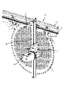
sheet
directly. US Patent Nos. 4095305, 6626195, 6681839, and 7530363 disclose
exemplary rectilinear frames adapted to be positioned adjacent or fastened to
a heat
exchanger tube sheet. Such assemblies are heavy, generally awkward to set up
and
utilize, and most require a substantial amount of space adjacent to or in line
with the
tube sheet which may limit the feasibility of using such assemblies. What is
needed
is an apparatus for precisely positioning one or more cleaning lances in
registry with
a heat exchanger tube sheet that is simple to erect, remains rigid, and takes
up
minimal space adjacent the tube sheet.
SUMMARY OF THE DISCLOSURE
[0003] The present disclosure directly addresses such needs. One embodiment of
a
frame apparatus for holding a flexible lance positioning mechanism adjacent to
and
spaced from a heat exchanger tube sheet in accordance with the present
disclosure
includes an upper guide rail, a lower guide rail, a positioner rail supported
from one
of the upper and lower guide rails and guided by the other of the upper and
lower
guide rails, and a rail clamp assembly fastened to a portion of a tube sheet.
This rail
clamp assembly operably holds one of the upper and lower guide rails in a
fixed
position with respect to the tube sheet. This rail clamp assembly has a flat
plate or
beam member adapted to be fastened to the tube sheet, a base plate spaced from
the flat plate by one or more threaded shafts, and one or more clamp fingers
rotatably fastened to the base plate. The one or more clamp fingers is
operable to
1
CA 02955049 2017-01-12
WO 2016/014626 PCT/US2015/041471
rotate toward the base plate when the base plate is drawn against the flat
plate or
beam member by rotating the threaded shaft.
[0004] In one embodiment the member is an elongated beam having the rail clamp
assembly at a distal end of the beam and a screw clamp assembly at a proximal
end
of the beam. In another embodiment the member is a generally trapezoidal
shaped
plate having a curved bottom edge and a plurality of apertures therethrough
adjacent
the bottom edge for receiving a plurality of bolts to fasten the member to the
tube
sheet. The base plate of the clamp assembly has a pair of spaced apart fingers
rotatably supported therein and a pair of spaced apart threaded shafts beneath
each
of the fingers fastened to the base plate.
[0005] Each one of the fingers engages a ball nose spring plunger in a first
position
permitting a rail to be attached to the assembly and in a second position
permitting
the rail to be translated along the base plate or rotatably adjusted relative
to the base
plate. The threaded shaft is operated to draw the base plate to the beam to
rotate
the one or more fingers to a third position clamping the rail and preventing
translation
and rotation of the rail with respect to the base plate and tube sheet face.
[0006] Further features, advantages and characteristics of the embodiments of
this
disclosure will be apparent from reading the following detailed description
when
taken in conjunction with the drawing figures.
DESCRIPTION OF THE DRAWINGS
[0007] FIG. 1 is a perspective view of a first exemplary embodiment of a
flexible
lance positioner frame apparatus in accordance with the present disclosure
oriented
against and fastened to an exemplary heat exchanger tube sheet.
[0008] FIG. 2 is a perspective view of a second exemplary embodiment of a
flexible
lance positioner device in accordance with the present disclosure oriented
against
and fastened to a heat exchanger tube sheet.
[0009] FIG. 3 is a perspective view of a third exemplary embodiment of a
flexible
lance positioner device in accordance with the present disclosure fastened to
a heat
exchanger tube sheet shown in FIGS. 1 and 2.
2
CA 02955049 2017-01-12
WO 2016/014626 PCT/US2015/041471
[0010] FIG. 4 is a separate perspective view of one of the four clamp arm
assemblies shown in FIG. 3.
[0011] FIG. 5 is an exploded view of the rail clamp assembly of the clamp arm
assembly shown in FIG. 4
[0012] FIG. 6 is a side view of one of the rail clamp assemblies in accordance
with
the present disclosure with the rail clamp assembly in a first detent position
and open
to receive a frame rail therein.
[0013] FIG. 7 is a side view as in FIG. 6 with the rail clamp assembly in a
second
detent position such that the frame rail is retained but remains rotatably and
axially
adjustable relative to the base plate.
[0014] FIG. 8 is a side view as in FIG.6 with the frame rail clamped in a
final fixed
position within the rail clamp assembly such that the frame rail is rotatably
and axially
fixed relative to the base plate.
[0015] FIG. 9 is a separate perspective view of a dual jaw clamp assembly
utilized in
the second exemplary embodiment of the positioner frame apparatus shown in
FIG.
2.
[0016] FIG. 10 is a separate side view of a hook clamp finger utilized in the
clamp
assemblies shown in FIGS. 2 through 9.
DETAILED DESCRIPTION
[0017] A first exemplary frame apparatus 100 is shown in FIG. 1 bolted to a
tube
sheet 102. The tube bundle is not shown in this figure for clarity, but it is
understood
that the tube sheet 102 essentially is the end face of a heat exchanger tube
bundle,
either removed from a heat exchanger or in place. The apparatus 100 has a top
generally horizontal guide rail 104 that is fastened to a common leg of a
rigid Y-
shaped metal support member 106. The other two legs of the support member 106
are bolted to the tube sheet flange that normally secures the heat exchanger
tube
side end cover (not shown). A bottom guide rail 108 is adjustably mounted and
aligned parallel to the top guide rail 104 via a bolt 110 through an arcuate
slot 112 in
a flat bracket 114 that is fastened to the center of the Y- shaped support
member
106 via another bolt 110.
3
CA 02955049 2017-01-12
WO 2016/014626 PCT/US2015/041471
[0018] A positioner support rail 120 is oriented orthogonal to the lower guide
rail
108, i.e. substantially vertically as shown in FIG. 1, and is driven by a
remotely
controlled air motor 122 horizontally along the lower guide rail 108. A
flexible lance
positioner drive assembly 124 is mounted on the positioner support rail 120.
The
position of the drive assembly 124 is changed along the support rail 120 via a
remotely controlled air motor and gear assembly 126 in order to align the
drive
assembly 124 in registry with particular tubes in the tube bundle to be
cleaned. The
flexible lance drive 124 can then insert or withdraw one or more flexible
lances (not
shown) into and out of the tubes to which it is aligned.
[0019] A second exemplary frame apparatus 200 in accordance with the present
disclosure is shown in FIG. 2. The apparatus 200 has an upper generally
horizontal
guide rail 204, a lower guide rail 206, and a positioner support rail 208 that
supports
a flexible lance positioner drive assembly 124 as in the first embodiment
shown in
FIG. 1. The upper guide rail 204 serves to provide mechanical alignment with
rows of
tubes present in the heat exchanger bundle. When so aligned, the drive
assembly
124 can be moved up and down along the support rail 208 to precise positions
in line
adjacent with selected tubes within the tube sheet 202. The lower guide rail
206
does not have to be installed parallel to the upper guide rail 204 as the
lower guide
rail follower carriage 209 can tolerate reasonable rotation within a plane
roughly
parallel to the face of the tube sheet 202. The lower guide rail 206 and lower
guide
rail follower carriage 209 serve to mechanically support the drive assembly
124 in
position and prevent deflection away from the tube sheet 202 generated by jet
thrust,
machine mass or force imparted to the system by the interaction between the
drive
assembly 124, the flexible lance(s)and the heat exchanger tubes.
[0020] Each of the upper and lower guide rails 204 and 206 is fastened to the
tube
sheet 202 via a dual jaw clamp assembly 210 shown in more detail in FIG. 9.
Each
clamp assembly 210 is designed to be fastened to the tube sheet 202 via a bolt
through the center hole 212 or through one of the slots 214 and preferably
another
bolt through the other one of the slots 214. The clamp assembly 210 has a
generally
trapezoidal flat mounting base plate 220 that has a curved base edge 222.
Parallel
to the base edge 222 are the curved slots 214 which sandwich therebetween the
center hole 212 above described. By mounting the base plate 220 to a tube
sheet
202 via bolts, (not shown), with at least one bolt in one of the slots 214,
the
4
CA 02955049 2017-01-12
WO 2016/014626 PCT/US2015/041471
orientation of the base plate 220 may be tilted to facilitate alignment of the
clamp
assembly 210 with respect to a row of tubes penetrating the tube sheet 202.
Alternatively the base plate 220 may be fastened to the tube sheet 202 via a
single
bolt through the center hole 212. In this latter case, the base plate cannot
be slid
along the slot, but can be rotated about the bolt axis to facilitate
alignment.
Preferably, however, at least one bolt in one of the slots 214 should be
utilized along
with another bolt in either the hole 212 or the other slot 214.
[0021] The drive mechanism/air motor 122 is remotely operated to move the
support
rail 208 back and forth along the upper guide rail 204. A follower roller
assembly 209
fastens the lower end of the support rail 208 to the lower guide rail 206.
This
follower roller assembly 209 restricts movement of the support rail 208 away
from
the tube sheet 202 while permitting free movement of the guide rail 208 back
and
forth along the lower guide rail 206. In addition, this follower roller
assembly 209
permits movement of the support rail 208 toward and away from the upper guide
rail
204 while maintaining the support rail 208 in a plane parallel to the tube
sheet 202.
It is to be understood that the above configuration may be reversed, with the
drive
mechanism 122 mounted on the lower guide rail 206 and the follower roller
assembly
209 mounted on the upper guide rail 204.
[0022] The dual clamp assembly 210 operation is included with the description
of
the following frame apparatus 300. FIG. 3 is a perspective view of a third
exemplary
flexible lance positioner frame apparatus 300 in accordance with the present
disclosure. This apparatus 300 is particularly designed to permit complete
installation of the apparatus 300 on a tube sheet 302 of a heat exchanger
without the
need for any hand tools and also permits installation to a tube sheet that
does not
have bolt holes on its peripheral flange.
[0023] Apparatus 300 includes an upper guide rail 304, a lower guide rail 306,
and a
positioner support rail 308. The positioner support rail 308 is moveably
fastened to
both the upper guide rail 304 and to the lower guide rail 306. A drive
mechanism
310 preferably including an air motor 122 is fastened to the upper end of the
positioner support rail 308. This drive mechanism 310 is remotely operated to
move
the support rail 308 back and forth along the upper guide rail 304. A follower
roller
assembly 312 fastens the lower end of the support rail 308 to the lower guide
rail
CA 02955049 2017-01-12
WO 2016/014626 PCT/US2015/041471
306. This follower roller assembly 312 restricts movement of the support rail
308
away from the tube sheet 302 while permitting free movement of the guide rail
308
back and forth along the lower guide rail 306. In addition, this follower
roller
assembly 312 permits movement of the support rail 308 toward and away from the
upper guide rail 304 while maintaining the support rail 308 in a plane
parallel to the
tube sheet 302. It is to be understood that the above configuration may be
reversed,
with the drive mechanism 310 mounted on the lower guide rail 306 and the
follower
roller assembly 312 mounted on the upper guide rail 304.
[0024] Each of the upper guide rails 104, 108, 204, and 304, the lower guide
rails
206, and 306, and the positioner support rail 120, 208 and 308 shown in FIGS.
1-3 is
preferably an aluminum extrusion 316 having, in cross section, a generally
rectangular tube shape having four side walls 318. An end view or cross
section of
one embodiment of this extrusion 316 is visible in FIGS. 6 through 8. Each of
the
four corners of the rail extrusion 316 extends outward to form an axially
extending
external rib 320. Preferably at least one of the side walls 318 of each guide
rail has
a series of spaced closed slots 322 forming essentially a ladder surface that
designed to operably engage with a drive sprocket (not shown) driven by one of
the
air motors 122 or 126 shown in FIGS. 1, 2 and 3.
[0025] The external ribs 320 on each of the rails 316 permit each rail 316 to
be
adjustably and securely held in a secure grip by the clamp mechanisms, either
dual
rail clamp assembly 210 or single rail clamp assembly 350, the operation of
which is
shown in FIGS. 6, 7 and 8.
[0026] As is best shown in FIG. 3, each of the rails 304 and 306 is fastened
securely
to the tube sheet 302 by a pair of rail clamp arm assemblies 325 in accordance
with
the present disclosure. One of the rail clamp arm assemblies 325 is separately
shown in a perspective view in FIG. 4. The rail clamp arm assembly 325 has a
rail
clamp 350 at a distal end of an elongated beam 326 and a screw clamp 328 at
the
proximal end of the beam 326. The beam 326 is preferably an elongated
rectangular
metal plate, and may be made of steel or high strength aluminum.
[0027] The screw clamp 328 includes a pair of cross bolts 330 and 332 that
pass
through smooth axially spaced bores spaced from the proximal end of the beam
326.
The cross bolt 330 is fastened to the beam 326 via a nut 334 tightened against
and
6
CA 02955049 2017-01-12
WO 2016/014626 PCT/US2015/041471
between the head of the bolt 330 and the beam 326. Another nut 336 on the
cross
bolt 330 sets a minimum jaw width position on the cross bolt 330.
[0028] The screw clamp 328 also includes a jaw member 338 that has two bores
therethrough spaced to match the spacing between cross bolts 330 and 332
adjacent one end of the jaw member 338. The jaw member 338 is also an
elongated
metal rectangular plate of steel or high strength aluminum. A caged nut 340 is
fixed
to an outer side of the jaw member 338 over one of the bores so that it is
threaded
onto and captures one end of the cross bolt 332. The other end of the cross
bolt 332
passing through the beam 326 is fixed to a cross bar handle 342. The screw
clamp
328 operates like a bench vice to capture and hold a portion of the heat
exchanger
flange 302 between the jaw member 338 and proximal end of the beam 326.
[0029] The screw clamp 328 is positioned with the beam 326 and jaw member 338
over the edge or rim of the tube sheet flange and bar handle 342 is manually
tightened to draw the beam 326 and jaw member 338 together against the tube
sheet 302. Different thicknesses of tube sheet 302 flanges may be accommodated
by changing the position of nut 336 on the bolt 330 or for considerable
increases in
flange with, using a longer bolt 330 and cross bolt 332. The rail clamp arm
assembly
325 may be positioned anywhere on the rim/flange of the tube sheet 302 so long
as
the screw clamp 328 can gain a secure purchase on the tube sheet 302. The jaw
member 338 and/or the proximal end of the beam 326 may optionally be fit with
locating pins (not shown) to fit within one of the bolt holes around the
rim/flange of
the tube sheet 302 if desired.
[0030] At the opposite end of the beam 326 in the rail clamp arm assembly 325
is a
single rail clamp assembly 350. This rail clamp assembly 350 is separately
shown in
an exploded perspective view in FIG. 5. The distal end 352 of the beam 326 has
a
threaded cross bore 354 therethrough. The distal end 352 also has a pair of
arcuate
slots 356 around and symmetrically spaced from the threaded cross bore 354
along
the beam 326.
[0031] The rail clamp assembly 350 essentially includes the distal end 352 of
the
beam 326, a threaded handle shaft 358, a base plate 360, a hooked clamp finger
362 and a static clamp jaw 364 across a bottom end of the base plate 360. The
base plate 360 is a generally rectangular flat metal plate having a bottom end
to
7
CA 02955049 2017-01-12
WO 2016/014626 PCT/US2015/041471
which is fastened the static clamp jaw 364. Alternatively the static metal
clamp jaw
364 may be integrally formed with the base plate 360. A top end of the base
plate
360 has a cutout recess or rectangular notch 366 sized to receive therein the
hooked
clamp finger 362. This finger 362 is mounted to rotate about an axle screw 368
that
extends across the recess 366 in the top end of the base plate 360.
[0032] The threaded handle shaft 358 preferably has a cylindrical portion 370,
a
threaded portion 372, and a smaller diameter distal threaded end 374. The
cylindrical portion 370 has a cross bore 376 through which a handle bar 378
extends. The handle shaft 358 also preferably has a flat washer 380 around a
shoulder of the threaded portion 372. The threaded portion 372 engages the
threaded bore 354. The smaller diameter threaded distal end 374 passes through
a
bore 382 through the base plate 360 such that the base plate 360 is fastened
securely to the distal end 374 of the handle shaft 358 when the shaft 358 is
assembled through the threaded bore 354 through the beam 326.
[0033] A guide pin or screw 361 is preferably fastened to and extends outward
from
a rear surface of the base plate 360 so as to ride within the slot 356 to
permit the
base plate 360 to be able to rotate through a limited arc about the bore 354
through
the beam 326. This guide pin 361 permits the rail clamp assembly 350 to have a
limited range of adjustment about the distal end of the beam 326.
[0034] A separate side view of the hook clamp finger 362 is shown in FIG. 10.
This
finger 362 is metal plate that resembles a claw hammer with a parallel sided
stem
portion 386 that merges with an upper portion 388 close to a cross bore 390.
The
finger 362 has opposite flat side surfaces 396 and a rear edge 398. The upper
portion 388 has a downwardly extending claw or hook portion 392 and an
opposite
hammerhead portion 394 that projects beyond the rear edge 398 of the parallel
sided
stem portion 386.
[0035] Each side surface 396 has a depression 400 above and preferably
slightly
offset from vertical alignment with the cross bore 390. Another depression 402
is
spaced on an arc from depression 400 from the cross bore 390 and toward the
hook
portion 392. Each of the depressions 400 and 402 is located so as to engage a
ball
nosed spring plunger 404 that projects from a bore through one or both sides
of the
base plate 360 into the recess 366. When the finger 362 is rotated on the axle
368
8
CA 02955049 2017-01-12
WO 2016/014626 PCT/US2015/041471
such that the plunger 404 engages the depression 402, the hammerhead portion
394
extends further beyond the rear of the base plate 360 and the hook or claw 392
is
raised to an install or release position as shown in FIG. 6 below. When the
ball
nosed spring plunger 404 engages the depression 400, the finger 362 rotates on
the
axle 368 such that the hook or claw 392 moves forward with respect to base
plate
360 and down with respect to the static metal clamp jaw 364. This detent
position
permits loose retention of the extruded rail 316 in the assembly as shown in
FIG. 7.
[0036] FIGS. 6-8 illustrate the operation of each of the rail clamp assemblies
350
shown in FIG. 3 and incorporated into the dual rail clamp assemblies 210 shown
in
FIG. 2. FIG. 6 is an end view of a single clamp assembly 350 or dual clamp
assembly 210 shown in an open first position for receiving a rail 316 therein.
It is to
be understood that rail 316 may be any one of rails 104, 108, 204, 206, 304,
306,
208 and 308 described above.
[0037] In the open first position shown in FIG. 6, the clamp assembly 350 is
fully
open. With the finger 362 in the position shown in FIG. 6, the ball nose
spring
plunger 404 engages the depression 402 to hold the finger 362 in an open
position.
The handle 378 is fully threaded into the beam 326 such that washer 380 abuts
against the beam 326. This pushes the base plate 360 laterally away from the
beam
326 to the position shown. In this FIG. 6, a rail 316 is either being placed
into the
assembly 350 or removed therefrom. In the former case, the corner rib 320 is
first
placed into the lower jaw 364 and then the rail 316 is simply rotated
counterclockwise to push the adjacent rib 320 of the rail 316 against the stem
portion
386 of the finger 362. This rotation causes the finger 362 to rotate clockwise
from
the first position until the stem portion 386 of the finger is almost flush
with the
surface of the base plate 360. At the same time, the ball nose spring plunger
404
now engages the depression 400. The user will feel a tactile snap as the
plunger
404 engages the depression 400. This corresponds to the finger 362 position
shown
in FIG. 7. The handle 378 is then rotated counterclockwise to a position shown
in
FIG. 7 to prevent the finger 362 from being returned to the open position
shown in
FIG. 6. With the finger 362 oriented as is shown in FIG. 7, the rail 316 is
securely
retained, but the rail 316 may be axially or rotatably moved within the
assemblies
350 to a desired position.
9
CA 02955049 2017-01-12
WO 2016/014626 PCT/US2015/041471
[0038] FIG. 8 shows the clamp assembly 350 in a rail locked position. The
handle
378 is further turned counterclockwise to pull the base plate 360 fully
against the
beam 326. This causes the hammerhead protrusion 394 on the upper portion 388
of
the finger 362 to draw flush against the beam 326 so that the hook 392 of the
finger
362 clamps the rail 316 against the base plate 360. This rigidly locks the
rail 316
between the jaw 364 and the hook 392 and against the base plate 360.
[0039] The operation of the clamp assembly 210 shown in FIGS 2 and 9 is
essentially the same as just described except that the base plate 224 has two
recesses for two fingers 362, the beam 326 is replaced by the base plate 220,
and
there are two handle shafts 358 drawing the base plate 224 against the plate
220 to
clamp the rail 316 in place. In the case of the clamp assembly 210, two hook
clamp
fingers 362 and all associated parts are installed to a single base plate 222.
Because they are mechanically affixed to the same plate, there is no rotation
permitted between the base plate 224 and the base 220, and therefore only
axial
translation of the rail 316 is permitted when in the retention position shown
in FIG. 7.
[0040] Many changes may be made to the device, which will become apparent to a
reader of this disclosure. For example, the fingers 362 may be shaped
differently
than above described. The rails 316 may not have four ribs 320 and could be
configured with no ribs at all.
[0041] All such changes, alternatives and equivalents in accordance with the
features and benefits described herein, are within the scope of the present
disclosure. Such changes and alternatives may be introduced without departing
from the spirit and broad scope of my invention as defined by the claims below
and
their equivalents.