Note : Les descriptions sont présentées dans la langue officielle dans laquelle elles ont été soumises.
ROBOTICALLY CONTROLLING MECHANICAL ADVANTAGE GRIPPING
TECHNICAL FIELD
[0001] The present disclosure relates to robotics, and more specifically to
robotic surgical
devices and/or systems for performing surgical procedures and methods of use
thereof.
BACKGROUND
[0002] Robotic surgical systems have been used in minimally invasive
medical
procedures.
[0003] Some robotic surgical systems included a console supporting a robot
arm, and at
least one end effector such as a forceps or a grasping tool that was mounted
to the robot arm.
During a medical procedure, the end effector was inserted into a small
incision (via a cannula) or
a natural orifice of a patient to position the end effector at a work site
within the body of the
patient.
[0004] Cables extended from the robot console, through the robot arm, and
connected to
wrist and/or jaw assemblies of the end effector. In some instances, the cables
were actuated by
motors that were controlled by a processing system with a user interface for a
surgeon or
clinician to be able to control the robotic surgical system including the
robot arm, the wrist
assembly and/or the jaw assembly.
1
Date recue / Date received 2021-11-02
CA 02957750 2017-02-09
WO 2016/025134 PCT/US2015/041442
[0005] In some instances, the wrist assembly had multiple degrees of
freedom for
movement of the jaw assembly using several cables. For example, for grasping
or cutting end
effectors, the wrist assembly provided the freedom for movement by allowing
changes to pitch,
yaw, or an opening and closing of the jaw assembly.
[0006] As demand for smaller end effectors increased, device manufacturers
continued to
develop end effectors such as grasping and cutting end effectors having
smaller cross-sectional
areas. These smaller cross-sectional areas reduced the total force that could
be applied between
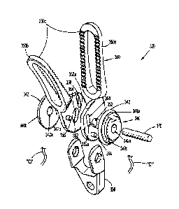
the jaws of the end effector. Additionally, designing end effectors supporting
multiple degrees
of motion required several cables. Each additional cable that was needed
further limited the
ability to reduce the cross sectional areas of these end effectors.
[0007] There is a need for end effectors having small cross-sectional areas
that are able to
provide higher forces between two jaws of the end effectors while providing
multiple degrees of
motion.
SUMMARY
[0008] An end effector of a surgical tool may include a housing having
proximal and
distal ends. The housing may define a longitudinal axis that extends through
the proximal and
distal ends. The end effector may include a jaw support shaft, a pair of jaw
members, an
articulation member, and a pair of cam pulleys.
[0009] The jaw support shaft may define a pivot axis that extends
therethrough. The
pivot axis can be transverse to the longitudinal axis of the housing. In
embodiments, the jaw
support shaft may be mounted to the housing.
2
CA 02957750 2017-02-09
WO 2016/025134 PCT/US2015/041442
[0010] The pair of jaw members may be supported on the jaw support shaft
and may be
pivotable about the pivot axis. Each of the pair ofjaw members may define an
arcuate slot
therethrough. Each arcuate slot may be adapted to receive the jaw support
shaft. The jaw support
shaft may be adapted to slide along the arcuate slots of the pair ofjaw
members to enable the
pair of jaw members to pivot about the pivot axis.
[0011] The articulation member may define a slot therethrough. The slot
may be adapted
to receive the jaw support shaft to support the articulation member between
the pair of jaw
members. The articulation member may include a pair of articulation pins
extending therefrom
and coupled to the pair ofjaw members. In some embodiments, at least a portion
of at least one
of the pair of articulation pins can be positioned proximally of the pivot
axis. In embodiments, at
least a portion of at least one of the pair of articulation pins may be
positioned distally of the
pivot axis. The articulation member may be rotatable about the jaw support
shaft to articulate the
pair of jaw members relative to the longitudinal axis. In some embodiments,
the pivot axis of the
jaw support shaft may be longitudinally offset from the pair of articulation
pins.
[0012] The pair of articulation pins may be adapted to couple to the pair
of jaw members.
Each jaw member of the pair of jaw members may define an articulation pin
opening adapted to
receive one of the pair of articulation pins to couple the articulation member
to the pair ofjaw
members. In some embodiments, the pair of jaw members may be adapted to
articulate relative
to the longitudinal axis of the housing to a yaw angle of about ninety degrees
in response to
rotation of the articulation member about the jaw support shaft. The pair of
jaw members may be
pivotable about the pivot axis while in an articulated position relative to
the longitudinal axis.
3
CA 02957750 2017-02-09
WO 2016/025134 PCT/US2015/041442
[0013] The pair of cam pulleys may be mounted to the housing and coupled
to the pair of
jaw members. The pair of cam pulleys may be rotatable about the pivot axis to
pivot the pair of
jaw members between open and closed conditions. In embodiments, the pair of
jaw members
may be adapted to pivot to a jaw angle of about sixty degrees in response to
rotation of at least
one of the pair of cam pulleys.
[0014] Each cam pulley of the pair of cam pulleys can be coupled to at
least one first
cable and the articulation member can be coupled to at least one second cable.
The at least one
first cable and the at least one second cable may be coupled to at least one
motor so that
actuation of the at least one motor articulates and/or pivots the pair of jaw
members.
[0015] In one aspect of the present disclosure, an end effector for use
and connection to a
robot arm of a robotic surgical system, wherein the end effector may be
controlled by at least one
cable extending from a motor of a control device of the robot surgical system
may be provided.
[0016] According to yet another aspect, a method of actuating an end
effector of a
robotic surgical system may be provided. The method may include rotating a cam
pulley secured
to a pair of jaw members to open or close the pair of jaw members about a
pivot axis; and
rotating an articulation member positioned between the pair of jaw members to
articulate the pair
of jaw members relative to a longitudinal axis of the end effector with a pair
of articulation pins
that extends from the articulation member, wherein at least one of the pair of
articulation pins
may be at least partially longitudinally offset from the pivot axis.
[0017] According to still another aspect, an end effector of a surgical
tool may be
provided. The end effector may include a housing, a jaw support shaft, a pair
of jaw members,
and a pair of cam pulleys.
4
CA 02957750 2017-02-09
WO 2016/025134 PCT/US2015/041442
[0018] Each of the pair of jaw members may define a support shaft slot
therethrough and
may include a pulley pin and a jaw pin extending therefrom. In embodiments,
the support shaft
slot of each of the pair of jaw members may be curvate. Each of the pair of
jaw members may
define a jaw pin slot adapted to receive an opposing one of the jaw pins of
the pair of jaw
members. In embodiments, the jaw pin slot may be curvate.
[0019] The pair of cam pulleys may be mounted to the jaw support shaft and
coupled to
the pair of jaw members. The pair of cam pulleys may be rotatable about the
pivot axis to pivot
the pair of jaw members about the jaw support shaft. Each of the pair of cam
pulleys may include
a pulley pin slot. The pulley pin slot may be adapted to receive the pulley
pin of a respective one
of the pair of jaw members. At least one cable may be secured to the pair of
cam pulleys. The at
least one cable may be movable to rotate at least one of the pair of cam
pulleys to pivot at least
one of the pair of jaw members about the pivot axis.
[0020] In embodiments, at least one first cable may be coupled to a first
one of the pair of
cam pulleys and at least one second cable may be coupled to a second one of
the pair of cam
pulleys. The first one of the pair of cam pulleys and the second one of the
pair of cam pulleys
may be coupled to at least one motor so that actuation of the at least one
motor effectuates at
least one of: (1) an articulating movement or (2) a pivoting movement of the
pair of jaw
members.
[0021] In one aspect, an end effector for use and connection to a robot arm
of a robotic
surgical system may be provided. The end effector may be controlled by at
least one cable
extending from at least one motor of a control device of the robot surgical
system. The end
CA 02957750 2017-02-09
WO 2016/025134 PCT/US2015/041442
effector may include a housing, a jaw support shaft, a pair of jaw members,
and a pair of cam
pulleys.
[0022] The pair of cam pulleys may be rotatable about the pivot axis to
effectuate at least
one of: (1) an articulating movement or (2) a pivoting movement of the pair of
jaw members
about the jaw support shaft.
[0023] In embodiments, the at least one cable may include at least one
first cable that
may be coupled to a first one of the pair of cam pulleys and at least one
second cable that may be
coupled to a second one of the pair of cam pulleys. The first one of the pair
of cam pulleys and
the second one of the pair of cam pulleys are coupled to the at least one
motor.
[0024] Further details and aspects of exemplary embodiments of the present
disclosure
are described in more detail below with reference to the appended figures.
BRIEF DESCRIPTION OF THE DRAWINGS
[0025] The accompanying drawings, which are incorporated in and constitute
a part of
this specification, illustrate embodiments of the disclosure and, together
with a general
description of the disclosure given above, and the detailed description of the
embodiment(s)
given below, serve to explain the principles of the disclosure, wherein:
[0026] FIG. 1A is a schematic illustration of a medical work station and
operating
console in accordance with the present disclosure;
[0027] FIG. 1B is a schematic, perspective view of a motor of a control
device of the
medical work station of FIG. 1A;
6
CA 02957750 2017-02-09
WO 2016/025134 PCT/US2015/041442
[0028] FIG. 2 is a perspective view of an end effector, according to an
embodiment of
the present disclosure, for use in the medical work station of FIG. IA,
illustrating one
embodiment of a jaw assembly thereof in an unarticulated and open condition;
[0029] FIG. 3 is a perspective view, with parts separated, of the jaw
assembly of FIG. 2;
[0030] FIG. 4 is a side view of the end effector of FIG. 2 with portions
of the jaw
assembly removed and/or shown in phantom for clarity, the jaw assembly being
illustrated in an
unarticulated and closed condition;
[0031] FIG. 5 is a side view of the end effector of FIG. 2 with portions
of the jaw
assembly removed and/or shown in phantom for clarity, the jaw assembly being
illustrated in an
articulated and closed condition;
[0032] FIG. 6 is a side view of the end effector of FIG. 2 with portions
of the jaw
assembly removed and/or shown in phantom for clarity, the jaw assembly being
illustrated in
another unarticulated and open condition;
[0033] FIG. 7 is a side view of the end effector of FIG. 2 with portions
of the jaw
assembly removed and/or shown in phantom for clarity, the jaw assembly being
illustrated in an
articulated and open condition;
[0034] FIG. 8 is a perspective view, with parts separated, of another
embodiment of a
jaw assembly; and
[0035] FIG. 9 is a perspective view, with parts separated, of yet another
embodiment of a
jaw assembly.
7
CA 02957750 2017-02-09
WO 2016/025134 PCT/US2015/041442
DETAILED DESCRIPTION
[0036] Robotically controlled end effectors in accordance with the present
disclosure
enable cable driven movement of compact jaw assemblies for increased
mechanical advantage
grasping. The end effectors described herein include an articulation member
that provides
bilateral articulation of the respective jaw assemblies up to approximately
ninety degrees from a
longitudinal axis of the end effector. At least one cam pulley of these end
effectors can be
rotated to position the jaw members thereof in an open condition so that the
jaw members define
a jaw angle up to approximately sixty degrees.
[0037] Embodiments of the presently disclosed end effectors are described
in detail with
reference to the drawings, in which like reference numerals designate
identical or corresponding
elements in each of the several views. As used herein the term "distal" refers
to that portion of
the end effector that is farther from the user, while the term "proximal"
refers to that portion of
the end effector that is closer to the user.
[0038] Referring initially to FIGS. lA and 1B, a medical work station is
shown generally
as work station 1 and generally may include a plurality of robot arms 2, 3; a
control device 4; and
an operating console 5 coupled with control device 4. Operating console 5 may
include a display
device 6, which may be set up in particular to display three-dimensional
images; and manual
input devices 7, 8, by means of which a person (not shown), for example a
surgeon, may be able
to telemanipulate robot arms 2, 3 in a first operating mode, as known in
principle to a person
skilled in the art.
[0039] Each of the robot arms 2, 3 may include a plurality of members,
which are
connected through joints, and an attaching device 9, 11, to which may be
attached, for example,
8
a surgical tool "ST" supporting an end effector 100, in accordance with any
one of several
embodiments disclosed herein, as will be described in greater detail below.
[0040] Robot arms 2, 3 may be driven by electric drives (not shown) that
are connected
to control device 4. Control device 4 (e.g., a computer) may be set up to
activate the drives, in
particular by means of a computer program, in such a way that robot arms 2, 3,
their attaching
devices 9, 11 and thus the surgical tool (including end effector 100) execute
a desired movement
according to a movement defined by means of manual input devices 7, 8. Control
device 4 may
also be set up in such a way that it regulates the movement of robot arms 2, 3
and/or of the
drives.
[0041] Medical work station 1 may be configured for use on a patient 13
lying on a
patient table 12 to be treated in a minimally invasive manner by means of end
effector 100.
Medical work station 1 may also include more than two robot arms 2, 3, the
additional robot
arms likewise being connected to control device 4 and being telemanipulatable
by means of
operating console 5. A medical instrument or surgical tool (including an end
effector 100) may
also be attached to the additional robot arm. Medical work station 1 may
include a database 14,
in particular coupled to with control device 4, in which are stored, for
example, pre-operative
data from living being 13 and/or anatomical atlases.
[0042] For a detailed discussion of the construction and operation of
medical work
station 1, reference may be made to U.S. Patent Publication No. 2012/0116416,
filed on
November 3, 2011, entitled "Medical Workstation".
9
Date recue / Date received 2021-11-02
CA 02957750 2017-02-09
WO 2016/025134 PCT/US2015/041442
[0043] Control device 4 may control a plurality of motors (Motor 1...n)
with each motor
configured to wind-up or let out a length of a cable "C" (FIG. 1B) extending
through each robot
arm to end effector 100 of the surgical tool. In use, as cables "C" are wound-
up and let out,
cables "C" effect operation and/or movement of each end effector 100 of the
surgical tool.
Control device 4 may coordinate the activation of the various motors (Motor
1...n) to coordinate
a winding-up or letting out a length of a respective cable "C" in order to
coordinate an operation
and/or movement of a respective end effector. Although FIG. 1B shows a single
cable "C" that is
wound up or let out by a single motor, in some instances two or more cables or
two ends of a
single cable may be wound up or let out by a single motor. For example, in
some instances, two
cables or cable ends may be coupled in opposite directions to a single motor
so that as the motor
may be activated in a first direction, one of the cables winds up while the
other cable lets out.
Other cable configurations may be used in different embodiments.
[0044] An end effector for connection to robot arms 2, 3 and for
manipulation by control
device 4, is generally designated as 100. As seen in FIG. 2, end effector 100
may include a wrist
assembly 110 and a jaw assembly 120 pivotally connected to wrist assembly 110.
Wrist
assembly 110 may include a wrist housing 112, in the form of a distally
extending clevis,
defining a first longitudinal axis "XI-X1 ." Wrist housing 112 defines a first
pivot axis "A-A"
that is oriented orthogonal to first longitudinal axis "X1-X1." In an
embodiment, first pivot axis
"A-A" may extend through first longitudinal axis "XI-XI." Wrist housing 112,
being in the
form of a clevis, may include a pair of spaced apart, opposed upright supports
112a, 112b
through which first pivot axis "A-A" extends. Each of opposed upright supports
112a, 112b
defines a plurality of openings 112c.
CA 02957750 2017-02-09
WO 2016/025134 PCT/US2015/041442
[0045] Wrist assembly 110 further may include a first support shaft 114a
and a second
support shaft 114b, each of which is secured within, and extends between, a
longitudinally
aligned pair of the plurality of openings 112c of opposed upright supports
112a, 112b. First
support shaft 114a may be disposed at a location along the first longitudinal
axis "XI-XI" that
may be longitudinally spaced apart from second support shaft 114b. Each of
support shaft 114a,
114b supports one or more cam pulleys 116. Each cam pulley 116 defines an
opening 116a
therethrough that receives one of the first and/or second support shafts 114a,
114b. One or more
of cam pulleys 116 can be rotatably mounted to, or fixedly secured to, one of
first and/or second
support shafts 114a, 114b. As can be appreciated, first and/or second support
shafts 114a, 114b
can support any number of cam pulleys 116 having any suitable shape or
dimension.
[0046] Turning now to FIG. 3, one embodiment of jaw assembly 120 may
include a jaw
housing 130, an articulating member 140, a pair of jaw members 150, a pair of
cam pulleys 160,
and a jaw support shaft 170.
[0047] Jaw housing 130, which may be in the form of a clevis, defines a
longitudinal axis
"X2-X2" that extends therethrough. Jaw housing 130 has a body 130a that
defines an opening
132 therethrough adapted and dimensioned to receive second support shaft 114b
to pivotally
connect jaw assembly 120 to wrist assembly 110. In particular, body 130a may
be positionable
on second support shaft 114b between a pair of cam pulleys 116. Body 130a may
include
opposed upright supports 134, 136 that extend distally from body 130a. Opposed
upright
supports 134, 136 are spaced apart and include inner surfaces therebetween in
the form of a
saddle 138. The inner surfaces 138 may define a U-shaped opening 138a adapted
to receive at
least portions of articulating member 140, the pair of jaw members 150, the
pair of cam pulleys
11
CA 02957750 2017-02-09
WO 2016/025134 PCT/US2015/041442
160, and jaw support shaft 170. Each of opposed upright supports 134, 136
defines a shaft
opening 134a therethrough adapted and dimensioned to receive jaw support shaft
170 to enable
support shaft 170 to support articulating member 140, the pair of jaw members
150, and the pair
of cam pulleys 160. Shaft openings 134a of opposed upright supports 134, 136
can be
longitudinally aligned with one another.
[0048] As seen in FIGS. 2 and 3, a second pivot axis "B-B," which extends
through
opposed upright supports 134, 136 (e.g., through shaft openings 134a), can be
oriented
orthogonal to the first pivot axis "A-A" and orthogonal to the first
longitudinal axis "XI-XI." In
some embodiments, the first longitudinal axis "XI-XI" may be parallel with the
second
longitudinal axis "X2-X2" (e.g., jaw assembly 120 may be in a longitudinally
aligned orientation
with respect to first longitudinal axis "Xl-X1"), and second pivot axis "B-B"
extends through
first longitudinal axis "XI-X1."
[0049] With reference again to FIG. 3, articulation member 140 may be
received in U-
shaped opening 138a of saddle 138 and may include a body 142 that has a
triangular
configuration. As can be appreciated, body 142 can have any suitable shape
and/or dimension.
Body 142 may include a bottom surface 142a, a pair of side surfaces 142b that
may be planar,
and a top surface 142c that tapers distally to a peak 142d. An elongate slot
144 may be defined
through body 142 between the pair of side surfaces 142b. Elongate slot 144 may
include a
proximal end 144a and a distal end 144b. A pair of articulation pins 146a,
146b extends from the
pair of side surfaces 142b at a location adjacent proximal end 144a of
elongate slot 144. Each
articulation pin 146a, 146b of the pair of articulation pins 146a, I46b may be
disposed in
mirrored relation with the other of the pair of articulation pins 146a, 146b
relative to elongate
12
CA 02957750 2017-02-09
WO 2016/025134 PCT/US2015/041442
slot 144. Articulation pin 146a of the pair of articulation pins 146a, 146b
can extend laterally
outwardly in a direction opposite articulation pin 146b of the pair of
articulation pins 146a, 146b.
The pair of articulation pins 146a, 146b can be secured on articulation member
140 such that at
least a portion of one or both of the pair of articulation pins 146a, 146b
remains positioned
proximal to a second pivot axis "B-B" (described in greater detail below) of
jaw assembly 120
that may be aligned with a central long axis 170a of jaw support shaft 170
while jaw support
shaft 170 may be positioned within elongate slot 144, including positions at
both proximal and
distal ends 144a, 144b of elongate slot 144.
[0050] With reference to FIGS. 1A, 1B, 2, and 3, one or more cables "C,"
using any
known fastening technique, may be secured to pulleys 160 to enable rotatable
movement of the
pulleys 160 in clockwise and/or counterclockwise directions about second pivot
axis "B-B" to
facilitate bilateral articulation of jaw assembly 120 about wrist assembly 110
relative to first
longitudinal axis "XI-XI" (described in greater detail below). For example, a
single cable "C"
can be at least partially wrapped around (e.g., at least 180 degrees), and/or
secured to, a single
pulley 160 along channel 166. In some instances, instead of a single cable "C"
wrapping around
a pulley 160, distal ends of a first pair of cables such as cables "Cl" and
"C2" can be secured to
different sides of a pulley 160 at any suitable location to allow clockwise
and counterclockwise
rotation of the pulley 160 via the cables. Any of these cables "C," including
cables "Cl" and
"C2" have proximal ends that can extend through robot arm 2 or 3 and which can
be operatively
associated with a respective first motor and/or at least one second motor (not
shown) of control
device 4.
13
CA 02957750 2017-02-09
WO 2016/025134 PCT/US2015/041442
[0051] Referring again to FIG. 3, the pair of jaw members 150 may include a
first jaw
member 150a and a second jaw member 150b. Each of the pair of jaw members 150
has a base
portion 152 and a jaw portion 154 extending distally from base portion 152. An
arcuate slot 156
may be defined through base portion 152 and may be adapted and dimensioned to
receive jaw
support shaft 170 therethrough. Arcuate slot 156 may be adapted and
dimensioned to enable jaw
support shaft 170 to slide between proximal and distal ends 156a, 156b of
arcuate slot 156 as
first and second jaw members 150a, 150b pivot about support shaft 170 relative
to second pivot
axis "B-B." An articulation pin opening 158a and a cam pin opening 158b are
defined through
each base portion 152. Jaw portion 154 can include a plurality of teeth 154a
on a grasping
surface thereof.
[0052] The pair of cam pulleys 160 may include a first cam pulley 160a and
a second
cam pulley 160b, each of which can be substantially disc-shaped. Each of the
pair of cam
pulleys 160 defines a shaft opening 162 therethrough adapted and dimensioned
to receive
support shaft 170. A cam pin 164 extends from each of the pair of cam pulleys
160. Each cam
pin 164 may be received in one of cam pin openings 158b of the pair of jaw
members 150. Each
of the pair of cam pulleys 160 defines one or more channels 166 in an outer
surface thereof. The
one or more channels 166 are adapted and dimensioned to be secured to one or
more cables such
as cables "C3" and/or "C4" to facilitate rotational movement of cam pulleys
160 and pivoting
movement of jaw members 150 between open and closed conditions (described in
greater detail
below.) As can be appreciated, cables "C3" and "C4" can be wrapped around
and/or secured to
one of the pair of cam pulleys 160 using any suitable fastening technique such
as those described
above with respect to cables "Cl" and "C2." Similar to cables "Cl" and "C2,"
cables "C3" and
"C4" have proximal ends that can extend through robot arm 2 or 3 and which can
be operatively
14
CA 02957750 2017-02-09
WO 2016/025134 PCT/US2015/041442
associated with a respective first motor and/or at least one second motor (not
shown) of control
device 4. In addition, any of the presently described cables "C," including
cables "Cl," "C2,"
"C3," and "C4," can be at least partially wound around one or more of cam
pulleys 116. Cam
pulleys 116 can function as cable guides for any of the presently described
cables "C."
[0053] In operation, control device 4 can activate one or more electric
drives or motors
connected thereto to rotate end effector 100 about first longitudinal axis "Xl-
Xl" in either
clockwise or counterclockwise directions to any suitable radial orientation
(e.g., 360 degrees) as
shown by a line designated "a" illustrated in FIG. 4. In order to articulate
the pair of jaw
members 150 about first pivot axis "A-A," while individual jaw members 150a,
150b are in any
radial orientation, the proximal ends of the one or more cables wrapped around
one of the
pulleys 160a or 160b (e.g. cables "Cl" and "C4" or cables "C2" and "C3") may
be drawn in a
proximal direction while the proximal ends of the other cables wrapped around
the other of the
pulleys 160b or 160a may be slackened. The direction of articulation about the
first pivot axis
"A-A" depends on the pulley 160a,b that is selected to have its proximal cable
ends drawn in the
proximal direction.
[0054] Articulation about pivot axis "B-B" may be achieved by drawing the
proximal
ends of cables of each respective pulley 160a and 160b that rotate each of the
pulleys 160a,b in
the same direction (e.g. cables "Cl" and "C2" or cables "C3" and "C4"), while
letting out the
other cable ends. Rotating each of the pulleys 160a,b causes jaw members 150
to rotate via cam
pins 164 on the pulleys 160a,b and articulating pins 146 on the articulating
member 140
interfacing with respective pin openings 158 on the base portion 152 of jaw
members 150. The
position of these pins 164 and 146 and pin openings 158 may be changes or
altered in different
CA 02957750 2017-02-09
WO 2016/025134 PCT/US2015/041442
embodiments. For example, pin 164 may be affixed to base member 152 in a
different location
and a respective pin opening 158 may be provided on the pulley 160. As
articulation member
140 pivots, the pair of articulation pins 146, while positioned in
articulation pin openings 158a of
the pair of jaw members 150, drives the pair of jaw members 150 therewith to
articulate the pair
of jaw members 150 relative to the first longitudinal axis "XI-XI." In
embodiments, the
individual jaw members 150a, 150b of the pair of jaw members 150 can be
articulated in
bilateral directions, namely, two opposed lateral directions. As illustrated
by angle "f3," depicted
in FIG. 5, the pair of jaw members 150 can be articulated in some instances up
to a boundary line
"L" (e.g., maximum yaw angle), which can be up to about a 90 degree angle
relative to the first
longitudinal axis "X1-X1" in each of the bilateral directions (e.g., about 180
degrees in total). In
embodiments, boundary line "L" can be coplanar with first pivot axis "A-A."
[0055] Additionally, in operation, in order to pivot one or both of the
pair of jaw
members 150 of end effector 100 about second pivot axis "B-B" of jaw assembly
120 between a
closed condition (FIG. 4) and an open condition (FIGS. 6 and 7), one of the
proximal ends of
cables "C3" and "C4" are drawn in a proximal direction as a result of an input
from control
device 4 to activate a third motor (not shown), and optionally activate a
fourth motor (not shown)
to let out the other of the proximal ends of cables "C3" and "C4," or vice
versa. Depending on
which one of the proximal ends of cables "C3" and "C4" are drawn in a proximal
direction will
determine which direction of pivot, about second pivot axis "B-B," may be
transmitted to
support cam pulleys 160a, 160b, through cam pins 164, to thus pivot first and
second jaw
members 150a, 150b.
16
CA 02957750 2017-02-09
WO 2016/025134 PCT/US2015/041442
[0056] In embodiments, first jaw member 150a can be pivoted separate and
independent
of second jaw member 150b, and vice versa. Additionally, and/or alternatively,
first and second
jaw members 150a, 150b can be simultaneously pivoted toward and/or away from
one another as
first and second jaw members 150a, 150b pivot between the closed and open
conditions. In
embodiments, first and second jaw members 150a, 150b can be pivoted up to a
maximum jaw
angle "0" of about 60 degrees, as depicted in FIG. 6. As seen in FIGS. 4, 6,
and 7, as first and
second jaw members 150a, 150b move between open and closed conditions,
articulation member
140 slides along arcuate slot 156 between proximal and distal ends 156a, 156b
thereof. For
example, in the closed condition (FIG. 4), jaw support shaft 170 may be
disposed in proximal
end 144a of elongate slot 144 and proximal ends of arcuate slots 156 of the
pair of jaw members
150, while in one of the open conditions (FIG. 6 and FIG. 7) jaw support shaft
170 may be
disposed in distal end 144b of elongate slot 144 and distal ends of arcuate
slots 156 of the pair of
jaw members 150. In this regard, pivoting movement of the pair of jaw members
150 to one of
the open conditions thereof enables the pair of jaw members 150 and the
articulation member
140 to axially translate along first longitudinal axis "XI-XI" in a proximal
direction (toward
wrist assembly 110) relative to line "L," jaw support shaft 170, and/or the
pair of cam pulleys
160, and vice versa with regard to pivoting movement of the pair of jaw
members 150 towards
the closed condition. As can be appreciated, one or more components of end
effector 100 can be
simultaneously (and/or separately/independently), rotated, articulated, and/or
pivoted.
[0057] Turning now to FIG. 8, a jaw assembly for connection to an end
effector of robot
arms 2, 3 and for manipulation by control device 4, in accordance with another
embodiment of
the present disclosure, is generally designated as 220. Jaw assembly 220 may
be substantially
similar to jaw assembly 120 and thus will only be described in detail herein
to the extent
17
CA 02957750 2017-02-09
WO 2016/025134 PCT/US2015/041442
necessary to describe differences in construction and/or operation from those
of jaw assembly
120. In particular, jaw assembly 220 may include a jaw housing 130, an
articulating member
240, a pair of jaw members 250, a pair of cam pulleys 160, and a jaw support
shaft 170.
[0058] Articulating member 240 may include a pair of articulating pins 242
extending
from opposed side surfaces thereof and defines an elongate slot 244
therethrough adapted and
dimensioned to slidably receive jaw support shaft 170. As seen in FIG. 8, each
of the pair of
articulating pins 242 may be positioned distally of elongate slot 244, and
thus, distally of central
long axis 170a of jaw support shaft 170, which as described above, may be
aligned with second
pivot axis "B-B" (see FIG. 2) when coupled to wrist assembly 110.
[0059] The pair of jaw members 250 may include a first jaw member 250a and
a second
jaw member 250b. Each of the pair of jaw members 250 defines an arcuate slot
252
therethrough that may be adapted and dimensioned to receive jaw support shaft
170. Arcuate
slot 252 may be adapted and dimensioned to enable jaw support shaft 170 to
slide between
proximal and distal ends of arcuate slot 252 as first and second jaw members
250a, 250b pivot
about support shaft 170 relative to central long axis 170a of support shaft
170 (e.g., and second
pivot axis "B-B" ¨ see FIG. 2). An articulation pin opening 254 and a cam pin
opening 256 are
defined through each of the pair of jaw members 250. Each articulation pin
opening 254 may be
positioned on one of the pair of jaw members 250 to receive one of
articulation pins 242 of
articulation member 240 and enable articulation member 240 to articulate the
pair of jaw
members 250 relative to first longitudinal axis "X 1 -X 1" similar to that
described above with
respect to articulation member 140. Each cam pin opening 256 may be positioned
on one of the
pair of jaw members 250 to receive one of cam pins 164 of cam pulleys 160 and
enable cam
18
CA 02957750 2017-02-09
WO 2016/025134 PCT/US2015/041442
pulleys 160 to pivot the pair of jaw members 250 between open and closed
conditions similar to
that described above with respect to the pair of jaw members 150.
[0060] Turning now to FIG. 9, a jaw assembly for connection to an end
effector of robot
arms 2, 3 and for manipulation by control device 4, in accordance with yet
another embodiment
of the present disclosure, may be generally designated as 320. Jaw assembly
320 may be
substantially similar to jaw assemblies 120, 220 and thus will only be
described in detail herein
to the extent necessary to describe differences in construction and/or
operation from those of jaw
assemblies 120, 220.
[0061] In general, jaw assembly 320 may include a housing 330, a jaw
support shaft 170,
a pair of cam pulleys 340, and a pair of jaw members 350.
[0062] The pair of cam pulleys 340 may include a first cam pulley 340a and
a second
cam pulley 340b. Each of the pair of cam pulleys 340 may be mounted to the jaw
support shaft
170 and has a body 342 defining a central bore 342a and a pulley pin slot
342b. The central bore
342 of each pulley 340 may be adapted to receive the jaw support shaft 170
therethrough. The
body 342 of each pulley 340 further defines a cable channel 344 that may be
adapted to receive
one or more cables therein, which may be at least partially wrapped around,
and/or secured
to,/within, channel 344. For example, a first cable "Cl" may be wrapped around
first cam pulley
340a and a second cable "C2" may be wrapped around second cam pulley 340b.
Instead of a
single cable wrapping around a pulley 340, in some instances two separate
cables terminating on
the pulley 340 may be used instead. The one or more cables may be movable
(e.g. via a motor ¨
see FIG. 1B) to rotate or pivot one or both of the pair of cam pulleys 340a,
340b about jaw
support shaft 170.
19
CA 02957750 2017-02-09
WO 2016/025134 PCT/US2015/041442
[0063] The pair of jaw members 350 may include a first jaw member 350a and
a second
jaw member 350b. Each of the pair of jaw members 350 defines a support shaft
slot 352 through
a proximal portion thereof and may include a pulley pin 354 and a jaw pin 356
extending from
the proximal portion on opposite side surfaces thereof. The support shaft slot
352 may be
adapted and dimensioned to receive jaw support shaft 170 and enable sliding
movement of jaw
support shaft 170 therein. In embodiments, support shaft slot 352 may be
disposed off-center of
a center of the proximal portion of one or both of the pair of jaw members
350. The support shaft
slot 352 of one or both of the pair of jaw members 350 may be curvate and can
include at least
one nub 352a. Each of the pair of jaw members 350 defines a jaw pin slot 358
adapted to
slidably receive an opposing one of the jaw pins 356 of the pair of jaw
members 350. The jaw
pin slot 358 can be curvate to provide a non-linear relationship between
pulley angle (e.g., a
rotational angle of one or both of the pair of pulleys) and jaw angle (e.g., a
rotational angle of
one or both of the pair of jaw members).
[0064] In embodiments, one or more of slots 352 and/or 358 can be shaped
to dictate a
ratio and motion profile of one or both of the pair of jaw members 150 as one
or both of the pair
of cam pulleys 350 are actuated. One or more of slots 352 and/or 358 can have
any suitable
profile (e.g., elongate, circular, elliptical, c-shaped, s-shaped, etc.) to
accommodate any suitable
relationship (e.g., linear, non-linear) between pulley angle and jaw angle.
[0065] In operation, the one or more cables are actuated to rotate one or
both of the pair
of cam pulleys 340 about jaw support shaft 170 such that jaw pins 356 slide in
jaw pin slots 358
and at least one of the jaw members 350b slidingly pivots about jaw support
shaft 170 via
support shaft slot 352.
CA 02957750 2017-02-09
WO 2016/025134 PCT/US2015/041442
[0066] Additionally, in operation, movement (e.g., pivoting) of one or
both of the pair of
cam pulleys 340 imparts pivoting and/or articulating movement of the pair of
jaw members 350
about jaw support shaft 170, depending upon the direction of rotation (e.g.,
clockwise/counterclockwise) and/or amount of rotational displacement of one or
both of the pair
of the pair of cam pulleys 350. As can be appreciated, the pair of jaw members
350 may be
adapted to pivot between open and closed conditions similar to that described
above with respect
to the pair of jaw members 150. The first and second cam pulleys 350a, 350b
can be rotated in
the same and/or opposite directions with respect to one another to impart the
pivoting and/or
articulating movement of the pair of jaw members 350. In embodiments, the
first and second
cam pulleys 350a, 350b can be rotationally displaced at the same and/or
different amounts to
impart the pivoting and/or articulating movement of the pair of jaw members
350.
[0067] The shape and dimension of support shaft slot 352 may enable the
pair of jaw
members 350 to slidingly pivot/rotate about jaw support shaft 170 so that the
first and second
jaw members 350a, 350b approximate one another (e.g., toward the closed
condition) in
substantially parallel relation. The load distribution along tissue engaging
surfaces 350c of the
pair of jaw members 350 may vary in part depending on the shape of the support
shaft slot 352
and the resultant angle and position of the pair of jaw members 350.
[0068] As can be appreciated, any of the presently described jaw
assemblies provide
increased mechanical advantage with force multiplication features thereof
(e.g., pins, slots,
cables and/or combinations thereof) for improved grasping. In particular,
multiplication of the
pulley angle with respect to the jaw angle amplifies force at tips (e.g.,
distal ends) of the jaw
members for an equivalent, or substantially equivalent, tension applied at a
proximal end of one
21
CA 02957750 2017-02-09
WO 2016/025134 PCT/US2015/041442
or more of the cables. This increased mechanical advantage enables a user to
manipulate thick
and heavy tissue by generating greater grasping force while minimizing tension
in the cables
and/or reducing mechanical stress on various components (e.g., cables,
pulleys, etc.) of the end
effector. In one embodiment, force multiplication features enable the one or
both of pair of jaw
members to open by 40 degrees when one or more of the pulleys rotate by 80
degrees.
[0069] Persons skilled in the art will understand that the structures and
methods
specifically described herein and shown in the accompanying figures are non-
limiting exemplary
embodiments, and that the description, disclosure, and figures should be
construed merely as
exemplary of particular embodiments. The present disclosure is not limited to
the precise
embodiments described, and that various other changes and modifications may be
effected by
one skilled in the art without departing from the scope or spirit of the
disclosure. Additionally,
the elements and features shown or described in connection with certain
embodiments may be
combined with the elements and features of certain other embodiments without
departing from
the scope of the present disclosure, and that such modifications and
variations are also included
within the scope of the present disclosure. Accordingly, the subject matter of
the present
disclosure is not limited by what has been particularly shown and described.
22