Note : Les descriptions sont présentées dans la langue officielle dans laquelle elles ont été soumises.
CA 02957796 2017-02-10
1
TISSUE POSITIONING =VICE
BACKGROUND OF THE INVENTION
Field of the Invention
[0002] This invention relates generally to tissue
positioning devices, and more particularly to devices for
repositioning tissues that have been displaced due to injury
or illness.
Description of the Related Art
[00031 Medical practitioners often see patients with
ailments caused by soft or hard tissue displacements relative
to the surrounding anatomy. Much effort is placed into
repositioning the tissue and keeping It in the correct
location. A common example is a broken bone, where the doctor
repositions the bone and restricts its movement via a cast
until the bones are healed.
[0004] A variety of different devices are used to
reposition tissue, such as casts and splints, screws and
plates, and spacers such as those used in the spine. These
devices work fine for their indicated uses, but may be
inadequate for a heavily articulatable joint such as the
shoulder.
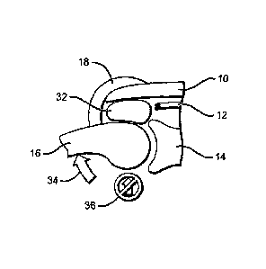
(0003J FIGS. 1-3 describe a
situation that can arise in the
shoulder. FIG. 1 depicts a simplified cross-sectional view of
the shoulder joint. The acromium 10, rotator cuff tendons 12,
the glenoid 14, the humerus 16, and the deltoid muscle 18 are
shown. In a healthy shoulder, the rotator cuff tendons 12 hold
CA 02957796 2017-02-10
2
the head of the humerus 16 in the cup of the glenoid 14, so
that even if muscles such as the deltoid 18 pull on the
humerus, its head remains in the cup of the glenoid.
[0006] However, in FIG. 2, rotator cuff tendons 12 have
been drastically reduced, such that they can no longer hold
the head of the humerus 16 in the glenoid 14 as deltoid muscle
18 pulls on the humerus. FIG. 3 shows that as the person
raises his arm, he utilizes his deltoid muscle 18, which
rotates the humerus 16 in an upward direction 20. Since the
rotator cuff tendons 12 are not holding humerus 16 in place,
its head tends to lift (24) out of the cup of glenoid 14,
creating a very painful movement for the patient and impairing
the capacity for activities above shoulder level.
[0007] The most common methods of treatment for this
condition are lengthy physical therapy, partial or total
shoulder replacement surgery, reverse total shoulder
arthoplasty, or doing nothing, in which case the patient
continues to experience pain and loss of strength.
SUMMARY OF THE INVENTION
[0008] The present invention is directed to a tissue
positioning device that addresses the issues noted above, in
that it intervenes with minimal inconvenience to the patient,
while allowing the performance of normal activities with
reduced pain and increased strength.
[0009] The device consists of a biocompatible member having
a size and shape suitable for placement within a space
adjacent to a tissue to be positioned; the tissue, which may
be hard or soft, forms a portion of an articulatable joint.
Once placed within the space, the member acts to maintain the
tissue in a desired position. The member may be a spacer
having a defined shape, or a bladder capable of receiving and
being at least partially expanded by a filler material.
CA 02957796 2017-02-10
3
[0010] When configured as a spacer, the member may be rigid
or flexible, and has a size and shape suitable for placement
within a space adjacent to a particular tissue. The spacer can
be made from any of a number of different materials, such as
silicone rubber and/or ultra high molecular weight
polyethylene (UHMWPE), as well as super-elastic or shape-
memory materials capable of being compressed for insertion
into the space, and then reverting to a preformed shape.
[0011] When the member is a bladder, the bladder has an
associated .deflated state and is capable of receiving and
being at least partially expanded by a filler material; a
valve is provided by which a filler material can be delivered.
The bladder is capable of insertion into the space adjacent to
the tissue when in its deflated state, and acts to maintain
the tissue in a desired position when at least partially
expanded by the delivery of filler material.
[0012] The bladder may be arranged such that it continues
to expand as long as additional filler material is delivered,
or to only expand up to a predetermined limit. The bladder can
made in whole or part from a variety of materials, including,
for example, silicone rubber, cross-linked polyethylene (PE),
polyester (PET), metal, woven Kevlar, UHMWPE, stainless steel,
and Nitinol. The filler material can be any of a number of
substances, including liquids, gases, a curable liquid such as
bone cement or urethane foam, or even a spring.
[0013] The present tissue positioning device may include an
attachment means by which the member can be secured to one or
more tissues such that it is maintained in a desired spatial
location. Suitable attachment means include a tab affixed to
or molded as part of the member, with the tab having a suture
embedded within it or containing a hole through which a suture
may be threaded. The bladder might also be arranged to
CA 02957796 2017-02-10
4
accommodate one or more attachment means such as bone anchors
that can be inserted into adjacent hard or soft tissue.
[0014] These and other features, aspects, and advantages of
the present invention will become better understood with
reference to the following description and claims.
BRIEF DESCRIPTION OF THE DRAWINGS
[0015] FIGs. 1-3 are cross-sectional views of a shoulder
joint which illustrate a typical tissue displacement condition
which may be addressed by the present invention.
[0016] FIG. 4 is a cross-sectional view of a shoulder joint
which illustrates the placement of a bladder-type tissue
positioning device within a space adjacent to a tissue to be
positioned.
(0017] FIGs. 5 and 6 are cross-sectional views of a
shoulder joint which illustrate how expanding the bladder of
FIG. 4 acts to maintain the tissue in a desired position.
[0016] FIGs. 7a and 7b are cross-sectional views of a
bladder and valve.
[0019] FIG. 8 is a cross-sectional view of a bladder which
uses a spring as a filler material.
[0020] FIG. 9 is a cross-sectional view of a bladder
illustrating several possible attachment means.
[0021] FIG. 10 is a cross-sectional view of a bladder
having a non-uniform thickness.
[0022] FIG. 11 is a cross-sectional view of a bladder in
which a portion of the bladder comprises a reinforced
material.
[0023] FIG. 12 is a cross-sectional view of a bladder to
which a secondary plate has been affixed.
[0024] FIG. 13 is a cross-sectional view of a bladder
composed of two or more different materials.
CA 02957796 2017-02-10
[0025] FIG. 14 is a cross-sectional views of a shoulder
joint which illustrates the placement of a spacer-type tissue
positioning device within a space adjacent to a tissue to be
positioned.
[0026] FIGS. 15a-15c are plan and sectional views of one
possible embodiment of a spacer-type tissue positioning
device.
DETAILED DESCRIPTION OF THE INVENTION
[0027] The present tissue positioning device consists of a
biocompatible member having a size and shape suitable for
placement within a space adjacent to a tissue to be
positioned. The tissue, which may be hard (such as bone, etc.)
or soft (such as muscle or tendon), forms a portion of an
articulatable joint. Once deployed within the space, the
member acts to maintain the tissue in a desired position. The
use of the device within a shoulder joint is described below,
but the device may also be used to address injuries within
other articulating joints.
[0028] A simplified cross-sectional view of a shoulder
joint which includes a tissue positioning device in accordance
with the present invention is shown in FIG. 4. The acromium
10, rotator cuff tendons 12, the glenoid 14, the humerus 16,
and the deltoid muscle 18 are shown. In a healthy shoulder,
the rotator cuff tendons 12 hold the head of humerus 16 in the
cup of glenoid 14, so that even if muscles such as deltoid 18
pull on the humerus, its head remains in the cup of the
glenoid.
[0029] Here, however, due to illness or injury, rotator
cuff tendons 12 have been significantly reduced such that they
no longer act to hold the head of humerus 16 in the cup of
glenoid 14. As noted above, this results in the head tending
to lift out of the cup of the glenoid, creating a very painful
CA 02957796 2017-02-10
6
movement for the patient and limiting function above shoulder
level.
[0030] The tissue positioning device is placed within a
space adjacent to a tissue to be positioned. Here, the
shortened rotator cuff tendons 12 leave an open space 30
adjacent to the tissue to be positioned, which in this example
is humerus 16. The device 32 is placed within space 30,
between acromium 10, humerus 16 and deltoid 18, preferably via
an arthroscopic port (skin or cannula) with the aid of a
scope, or through a larger skin incision with direct
visualization.
[0031] Device 32 may be in the form of a spacer which has a
generally defined shape when in place within the space, or a
bladder which can be at least partially expanded when in,place
within the space. A bladder-type tissue positioning device is
discussed first.
[0032] The method by which a bladder-type device might be
used is illustrated in FIGS. 5 and 6. In FIG. 5, bladder 32 is
shown in an expanded state, with the patient's arm hanging
straight down. In FIG. 6, the patient lifts (34) his arm and
humerus 16 with the aid of deltoid 18. Previously, this motion
tended to cause the head of humerus 16 to lift out of the cup
of glenoid 14. Now, however, there is no upward translation
(36), because expanded bladder 32 places a downward force on
the head of humerus 16, with the aid of backing from acromium
10. This bladder can also be attached to one or multiple
structures such as the glenoid or acromium, as discussed
below.
[0033] Depending on the specific application, bladder 32
might be made to be expandable, expandable up to a
predetermined limit, or not expandable at all if its fit
within the space is proper without expansion. In the latter
case, the bladder becomes more like a defined-sized spacer.
CA 02957796 2017-02-10
7
One advantage of using a bladder which is expandable is that
the bladder can be placed in the shoulder via a small portal,
and then expanded to a much larger size once positioned within
the joint - thus minimizing patient trauma due to inserting a
large fixed-size device.
[0034] Various details for possible bladder-type
embodiments are illustrated in the cross-sectional views shown
in FIGs. 7 to 13. In FIG. 7a, tissue positioning device 40
includes a bladder 32 and a valve 34 by which a filler
material can be delivered into the bladder. Many different
types of valves could be employed, including, for example, a
needle-piercable rubber type or a spring-loaded ball type. The
valve may be integral to the bladder, as shown in FIG. 7a, or
tethered to the bladder via a communicating tube 42 as
illustrated in FIG. 7b. The valve preferably enables bladder
32 to be easily filled, and then allow no leakage of the
filler material. The valve may be a one-way valve which only
allows filler material to be added to the bladder, or a two-
way valve which would also allow for removal of the material
from inside bladder 32, in order to deflate the bladder as
required. The valve is preferably positioned just below the
skin such that it can be easily accessed using, for example, a
syringe.
[0035] The bladder cross-section shown in FIGs. 7a and 7b
is slightly ovoid, but the shape and size can be almost
anything that properly matches the anatomy in need of repair
and which fits within the available space.
[0036] Bladder 32 is expanded by way of a filler material
44 delivered via valve 34. The filler material can be one
substance or a combination of many different substances. The
filler material's properties must allow for adequate expansion
of bladder 32, and must adequately hold the head of humerus 16
in place during manipulation. Examples of suitable filler
CA 02957796 2017-02-10
8
materials include air or any other gas, silicone, saline or
any other liquid, a gel such as hyaluronic acid, and cured
(reacting) substances such as bone cement or urethane foams.
[0037] As shown in FIG. 8, filler material 44 might also
take the form of a spring. Such a spring can be compressed
while the bladder is being positioned, and allowed to expand
once in place. The spring can be made of any appropriate metal
or plastic material, such as Nitinol. The spring might also be
a super-elastic or shape memory material capable of being
compressed for insertion into the space, and then reverting to
a preformed shape. For example, the spring could be made from
a shape memory material that is temperature activated so that
it expands once the device warms to body temperature. The
spring could be made to be expandable in one, two or three
dimensions, as needed.
[0038] The present tissue positioning device may include an
attachment means by which the member can be secured to one or
more anatomical structures such that it is maintained in a
desired spatial location. Various possible attachment means
are illustrated in FIG. 9. For example, tabs 50 can be affixed
to or molded as part of member 52, which can be either a
bladder or defined-shape spacer. The tab may have a suture 54
embedded within it, or contain a hole 56 through which a
suture may be threaded; the suture could then be tied to, for
example, a bone anchor, or directly to other hard or soft
tissue (not shown) as appropriate.
[0039] Another possibility is to provide a tab 57 to which
an anchor device 58 such as a bone anchor or tack has been
affixed, or through which an anchor device can be routed. The
anchor device or devices would then be attached to appropriate
hard or soft tissue as needed.
[0040] Various possibilities related to the composition of
the bladder are addressed in FIGS. 10-13. In the case of the
CA 02957796 2017-02-10
9
shoulder joint, there may be concern with wear on the side of
the bladder that contacts the moving humeral head, or with
retaining the general bladder structure. As such, a bladder
with a uniform wall thickness and composition may have to be
modified. One possible modification is illustrated in the
cross-sectional view of bladder 60 in FIG. 10. Here, the side
of the bladder which rubs against the humeral head will be
thickened (62) to create a more durable wall.
[0041] Another possibility is shown in FIG. 11, in which at
least a portion of the bladder 70 comprises a reinforced
material 72, to reduce the degradation of the bladder due to
its contact with the tissue to be positioned. A reinforced
material could also be used to strengthen the attachment tabs
referred to above. This material could be a non-easily abraded
material such as a woven Kevlar, UHMWPE, stainless steel,
Nitinol, etc. The reinforced material might also be in the
form of a mesh affixed to the side of bladder 70, which
contacts the tissue to be positioned and thereby protects the
bladder.
[0042] In FIG. 12, a secondary plate 80 is affixed to the
bottom of a bladder 82 to act as a buffer against abrasion.
The plate's material, as with any of the materials that
contact the tissue to be positioned, may have a lubricious
quality such as UHMWPE. A thin layer of Nitinol which can be
unfurled in the joint may also work as a buffer layer.
[0043] Another possibility is shown in FIG. 13, in which
the member 90 is made from two or more different materials.
For instance, the portion 92 that contacts the humeral head
may be a hard lubricious plastic, with an expandable rubber
bladder portion 94 overmolded onto portion 92 which can be
properly filled to occupy the space in question. Portion 92
may also contain a molded-in lubricant, such as silicone oil,
to help minimize wear. One consideration in choosing the
CA 02957796 2017-02-10
material(s) for this embodiment, as with all previously
discussed embodiments, is the need to minimize wear on the
tissue being positioned.
[0044] The material for the bladder can be flexible (e.g.,
silicone rubber) or relatively non-expanding (e.g., cross-
linked PE). The bladder could also be made of metal, in the
form of a bellows, for example, which can be inflated to the
desired size. Other possible bladder materials include, but
are not limited to, polyester (PET), metal, woven Kevlar,
ultra high molecular weight polyethylene (UHMWPE), stainless
steel, and Nitinol.
[0045] A tissue positioning device in accordance with the
present invention may be either a bladder-type as described
abOve, or a spacer-type, in which the member has a generally
defined shape when in place within the space and acts to
maintain a particular tissue in a desired position.
[0046] A cross-sectional view of a spacer-type tissue
positioning device as might be used within a shoulder joint is
shown in FIG. 14. As before, device 100 is placed within a
space created by the degradation of rotator cuff tendons 12.
Once in place, device 100 acts to maintain a particular tissue
in a desired position - here, spacer 100 acts to maintain the
head of humerus 16 in the cup of glenoid 14.
[0047] Device 100 can be rigid or flexible, or some
portions may be rigid and others flexible, as needed. The
device can be made from a wide variety of materials, such as
silicone rubber and/or UHMWPE. A molded-in lubricant might
also be used, to reduce friction between the spacer and the
tissue being positioned. The device might also be made from a
composite material, such that different portions of the member
have different physical characteristics - for example, the
spacer might be designed such that the surface that contacts
the humerus is relatively hard, while the surface that
CA 02957796 2017-02-10
11
contacts the acromium is relatively soft. Some or all of a
spacer-type tissue positioning device might also be made from
a super-elastic or shape-memory material capable of being
compressed for insertion into the space, and then reverting to
a preformed shape.
(00413] As with bladder-type embodiments, the spacer may
include one or more attachment means by which it can be
secured to nearby tissues or anchor devices. For example, tabs
102 can be affixed to or molded as part of member 100; the tab
could have a suture embedded within it, or contain a hole
through which a suture may be threaded. An anchor device (not
shown) such as a bone anchor or tack might also be affixed to
or routed through one or more tabs. The sutures or anchor
devices would then be attached to appropriate hard or soft
tissue as needed.
(0049] The device is preferably designed to have a size and
shape suitable for placement within a given space and for
positioning a particular tissue. For example, a spacer-type
device designed to maintain the head of humerus 16 in the cup
of glenoid 14 may have a cup-like recess within the surface of
the spacer that contacts the humerus. This is illustrated in
FIGs. 15a. (plan view), 15b (cut along section line A-A), and
15c (cut along section line B-B); here, the surface which
contacts the acromium 10 is generally rounded, while the
opposite 'surface includes a recessed space 104 to assist in
maintaining the humeral head in the proper position.
(0050] In practice, it may be necessary to insert one or
more trial devices, to make sure that the proper it is
achieved or the proper bladder or spacer is used. A measuring
forceps might be employed to obtain the size of the space in
which the device is to be placed, in order to choose the
correct device size.
CA 02957796 2017-02-10
12
The scope of the claims should not be limited by the
preferred embodiments set forth in the examples, but should
be given the broadest interpretation consistent with the
description as a whole