Note : Les descriptions sont présentées dans la langue officielle dans laquelle elles ont été soumises.
CA 02958006 2017-02-14
TITLE:
CONTINUOUS CARBON FIBER SUCKER ROD AND METHOD OF
MANUFACTURE
CROSS-REFERENCE TO RELATED APPLICATIONS:
[0001] This application claims priority of United States Provisional Patent
Application
serial no. 62/297,470 filed February 19, 2016.
TECHNICAL FIELD:
[0002] The present disclosure is related to the field of sucker rod
engineering and
design, in particular, composite sucker rod assemblies for use in down-hole
vertical lift
oil extraction.
BACKGROUND:
[0003] Sucker rods for use with vertical lift rod pumps, actuated by surface
units (also
referred to as surface units, rocking horse or pump jacks), are traditionally
made from
individual lengths of steel rod sections that are connected together by
threaded
couplings. The individual sucker rods are typically 25 feet, 30 feet or 37.5
feet in length
and are connected together with couplings to form a sucker rod string. A
typical sucker
rod string is from 700 to 10,000 feet or more in length. The sucker rod string
connects
the vertical lift surface device to the down-hole pump unit. The design length
of the
traditional sucker rod is for service convenience. Work-over derrick rigs are
brought into
position above the well to pull the string and access the down-hole pump for
service.
The height of the work-over rig derrick determines the individual segment
length of a
sucker rod that can be pulled one at a time until the entire sucker rod string
is pulled out
of the well. The process to incrementally pull each sucker rod in order to
access the
down-hole pump for service requires noteworthy time, manpower and expense.
1
26035172_1INATDOCS
CA 02958006 2017-02-14
[0004] Fiberglass sucker rods the same lengths as steel sucker rods have also
been
used. Carbon fiber sucker rods as described in U.S. Provisional Application
No.
62/003,437 and U.S. Provisional Application No. 61/903,194 (both of these
applications
are incorporated by reference in their entirety into this application)
describe light-weight,
low-stretch and corrosion resistance properties compared to steel and
fiberglass rods.
[0005] Continuous steel sucker rod strings in a variety of forms have also
been
developed. One perceived advantage of continuous steel sucker rods is the
elimination
of the many threaded coupling joints that can fatigue and break on
conventional sucker
rod strings. Another advantage of continuous sucker rods is rapid deployment
and
removal from the well bore. However, continuous steel sucker rod strings are
still
heavy, subject to stress corrosion cracking and require large specialized
spools and
techniques to coil the product for transport, installation and service. A
continuous
carbon fiber sucker rod would be attractive to the user because of its
lightweight, high
strength, low stretch and corrosion resistance provided it could be reasonably
coiled
without damage. To be practical, a continuous length of sucker rod must be
coiled to a
diameter that can be easily transported over highways and narrow roads to
deliver it to
the well site.
[0006] A simple round monolithic pultruded carbon fiber rod could be made in a
suitably
long length from 1,000 to 10,000 feet for vertical lift oil well applications
as a continuous
length rod. The challenges to make a practical and effective continuous sucker
are
associated with the terminations and coiling. A continuous length carbon fiber
rod for
the application would need to be made in various sizes from 1/2 inch diameter
to 1/4 inch
diameter to be suitable to be used in the top 60% or more of the sucker rod
string.
2
26035172_1INATDOCS
CA 02958006 2017-02-14
Monolithic pultruded carbon fiber rods in these diameters are very stiff in
terms of
bending. Considerable stress must be applied to coil such a product and the
resultant
strain can cause failure in the unidirectional composite due to the low inter-
laminar
strength associated with these materials. The end result is the coiled
diameter must be
unreasonably large (hence not easily transported) to manage the stress and
strain
energy and not cause damage to the carbon fiber rod. One early attempt at a
continuous carbon fiber sucker rod utilized a pultruded rectangular strap
configuration
(approximately 3/16 inch thick by 1 and 1/4 inch wide in cross section) that
could be
coiled in a reasonably small diameter. While convenient to coil, this product
did not gain
wide acceptance for other reasons primarily the strength of the terminations.
Other
attempts at a continuous carbon fiber sucker rod have utilized an oval cross
section for
the pultruded rod such that it can be coiled in a slightly smaller diameter
than a round
rod. Even an oval cross section suitable for the sucker rod application has
considerable
strain when coiled at a reasonable diameter that can be damaging to the
composite. A
secondary related but still important criterion for a continuous carbon fiber
sucker rod is
the termination required at each end. The termination must be as close to the
strength
of the mid-span of the rod as possible to be usable. A strong and reliable
termination is
difficult to make on a monolithic round or oval pultruded carbon fiber rod
because the
adhesively bonded terminus is only attached to the outer surface of the
monolithic cross
section rod and not to the individual fibers or strands that make up the
carbon fiber rod.
[0007] It is, therefore, desirable to provide a continuous carbon fiber sucker
rod that
overcomes the shortcomings of the prior art.
3
26035172_11 NATDOCS
CA 02958006 2017-02-14
SUMMARY:
[0008] A continuous carbon fiber sucker rod assembly and its method of
manufacture
are provided.
[0009] Broadly stated, in some embodiments, a method can be provided for
manufacturing a length of rod, the method comprising the steps of: drawing a
plurality of
pultruded carbon fiber rods through a collector die to organize the plurality
of pultruded
carbon fiber rods into a predetermined cross-section shape; then drawing the
plurality of
pultruded carbon fiber rods through an extrusion die; and encapsulating the
plurality of
pultruded carbon fiber rods in a jacket of heated thermoplastic polymer by
extruding the
heated thermoplastic polymer about the plurality of pultruded carbon fiber
rods through
the extrusion die.
[0010] Broadly stated, in some embodiments, the method can further comprise
the step
of spooling the encapsulated plurality of pultruded carbon fiber rods.
[0011] Broadly stated, in some embodiments, the method can further comprise
the step
of cooling the encapsulated plurality of rods after exiting the extrusion die.
[0012] Broadly stated, in some embodiments, the method can further comprise
the step
of fitting an end fitting cone onto at least one end of the length of rod, the
end fitting
cone further comprising a coupling pin.
[0013] Broadly stated, in some embodiments, a system can be provided for
manufacturing a length of rod, the system comprising: at least one spools for
providing
a supply of a plurality of pultruded carbon fiber rods; a collector die for
organizing the
plurality of pultruded carbon fiber rods into a predetermined cross-section
shape; an
extrusion die configured for encapsulating the organized plurality of
pultruded carbon
4
26035172_1 NATDOCS
CA 02958006 2017-02-14
fiber rods with heated thermoplastic polymer to form the length of rod; and a
puller unit
configured for pulling the encapsulated plurality of pultruded carbon fiber
rods from the
at least one spool through the collector die and the extrusion die.
[0014] Broadly stated, in some embodiments, the system can further comprise a
take-up
spool for spooling the length of rod.
[0015] Broadly stated, in some embodiments, the system can further comprise a
cooling
trough configured for cooling the length of rod after exiting the extrusion
die.
[0016] Broadly stated, in some embodiments, the system can further comprise
means
for fitting an end fitting cone onto at least one end of the length of rod,
the end fitting
cone further comprising a coupling pin.
[0017] Broadly stated, in some embodiments, a length of rod can be
manufactured
using the method or the system as set forth above.
[0018] Broadly stated, in some embodiments, the length of rod can further
comprise an
end fitting cone fitted onto at least one end of the length of rod, the end
fitting cone
further comprising a coupling pin.
[0019] Broadly stated, in some embodiments, one or more of the pultruded
carbon fiber
rods can comprise a composition of carbon fiber and epoxy.
[0020] Broadly stated, in some embodiments, the composition can further
comprise one
or more from a group comprising of fiberglass, phenolic resin, vinyl ester
resin,
polyester resin, benzoxyzene resin and cyanurate ester resin.
[0021] Broadly stated, in some embodiments, the thermoplastic polymer can
comprise
one or more of a group comprising of high density polyethylene,
polyetherimide,
polyphenylenesulfide and polyetheretherketone.
26035172_11 NATDOCS
CA 02958006 2017-02-14
BRIEF DESCRIPTION OF THE DRAWINGS:
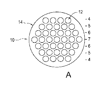
[0022] Figure 1A is a side elevation cross-section view depicting a round
carbon fiber
sucker rod jacketed by an extruded polymer jacket and comprising 37 each 3.3
mm
pultruded fiber rods.
[0023] Figure 1B is a side elevation cross-section view depicting a round
carbon fiber
sucker rod jacketed by an extruded polymer jacket and comprising 30 each 3.3
mm
pultruded fiber rods.
[0024] Figure 10 is a side elevation cross-section view depicting an oval
carbon fiber
sucker rod jacketed by an extruded polymer jacket and comprising 29 each 3.3
mm
pultruded fiber rods.
[0025] Figure 10 is a side elevation cross-section view depicting a polygonal
carbon
fiber sucker rod jacketed by an extruded polymer jacket and comprising 37 each
3.3
mm pultruded fiber rods.
[0026] Figure 1E is a side elevation cross-section view depicting a polygonal
carbon
fiber sucker rod jacketed by an extruded polymer tube drawn down onto 37 each
3.3
mm pultruded fiber rods.
[0027] Figure 2 is a side elevation view depicting a system carrying out a
continuous
extrusion process, comprising strand spools, collector plate, cross head
extruder, water
chill trough downstream of the hot extrusion die, a caterpillar puller device
and take up
spool.
[0028] Figure 3 is a side elevation view depicting one embodiment of a
terminus end
fitting and a short length of rod exiting the end fitting.
6
26035172_1INATDOCS
CA 02958006 2017-02-14
DETAILED DESCRIPTION OF EMBODIMENTS:
[0029] In some embodiments, a continuous sucker rod assembly can be provided,
comprising of a plurality of parallel carbon fiber and epoxy composite
strength elements,
referred to as "strands" to create a light weight, corrosion and fatigue
resistant sucker
rod assembly. While carbon fiber/epoxy composite strands are uniquely suited
for the
sucker rod application, other high strength fibers and matrix resins can be
also used in
the manner described herein. The individual pultruded strands, in some
embodiments,
can be 2 to 3 millimeters ("mm") in cross-section when made from carbon fiber
and
epoxy resin although smaller and larger diameter strands can be employed
depending
on the application. The number of strands bundled together can determine the
strength
and stiffness of the continuous sucker rod. The individual strands can be held
together
by encapsulating the strands in a thermoplastic polymer, such as High Density
Polyethylene ("HDPE"), Polyetherimide ("PEI"), Polyphenylenesulfide ("PPS"),
Polyetheretherketone ("PEEK") or any other suitable thermoplastic polymers for
down-
hole use, as well known to those skilled in the art.
[0030] In some embodiments, a method to encapsulate the bundle of pultruded
carbon
fiber strands can comprise the steps of running the bundle of strands through
a cross-
head extruder to form a polymer jacket over and around the bundled strands. By
this
method, long lengths of bundled rod on the order of 1,000 to 12,000 feet in
length can
be practically encapsulated to be handle-able and coil-able.
[0031] In some embodiments, the function of the thermoplastic encapsulation
can be
three-fold. First, it can provide a means of holding the bundle of parallel
composite
strands together. Second, it can allow the composite strands to twist a small
amount
7
26035172_11 NATDOCS
CA 02958006 2017-02-14
when the sucker rod is coiled. Third, it can provide a wear-resistant
encapsulation of
the strength elements when they rub against the inner wall of the oil well
tubing as the
surface unit moves the rod up and down to actuate the down-hole pump.
[0032] When a carbon fiber sucker rod made in this manner is coiled, the
bundled high
modulus strands, which are parallel when encapsulated, can progressively twist
since
the thermoplastic encapsulation is an unreinforced and lower modulus material.
The
amount of twist can be very small at any specific location along the length of
the sucker
rod. However, the twist over a long length of sucker rod can be significant
because it
progressively develops as the sucker rod is coiled. The twist can be
automatically and
naturally removed as the sucker rod is deployed off the spool due to the
elastic
properties of the encapsulation polymer. This is in contrast to a monolithic
pultruded
composite rod wherein the outer fibers are put in extreme tension and the
inner fibers
are put in extreme compression when the rod is coiled and the resin matrix is
too stiff to
allow twist when coiling. Additionally, there is significant inter-laminar
shear stress
when a monolithic composite rod is coiled. This results in significant strain
energy and
potential damage to the composite.
[0033] In some embodiments, a carbon fiber rod can be manufactured in the
following
manner. The carbon fiber/epoxy composite strands can first be pultruded.
Carbon fiber
and epoxy can be used in some embodiments, but other high-strength fibers such
as
fiberglass and matrix resins such as phenolic, vinyl ester, polyester resin,
benzoxyzene,
cyanurate ester, amongst others well known to those skilled in the art, can be
used in
combination with the fiber to make the strands. In some embodiments, the
strands can
be pultruded in multiple streams at lengths of 2,000 to 12,000 feet, the
length
8
26035172_1INATDOCS
CA 02958006 2017-02-14
dependent only on the length of the carbon fiber spool and coiled on
individual spools
after pultrusion. Because of the small size of the individual strands, they
can be coiled
on conventional cable spools as small as 18 inches in diameter when the rods
are in the
2 to 3 mm diameter range.
[0034] After pultrusion, the strands can be individually unspooled and brought
together
into a parallel bundle using collector plates. There can be a generally round
natural
nesting geometry to the bundle since it is made of a plurality of parallel
strands that are
typically round. For example, a bundle of 37 pultruded rods (12) of 3.3 mm
diameter
can form sucker rod (10) having a polygon cross-section shape approximately
1/4 inches
round, as shown in Figure 1A, wherein pultruded rods (12) can be encapsulated
in
extruded HDPE jacket (14). Other naturally generally round bundles, meeting
the
strength and stiffness requirements of typical oil wells, can use 14, 19 or 30
strands of
pultruded rods (12) to form sucker rod (10) encapsulated in jacket (14),
although other
combinations can be used. Figure 1 B shows a bundle comprising 30 pultruded
rods
(12) encapsulated in jacket (14) to form sucker rod (10). The bundled
configuration can
also be tailored to create a generally oval cross section that is more easily
coiled.
Figure 1C shows an oval bundle comprising 29 pultruded rods (12) encapsulated
in
jacket (14) to form sucker rod (10). In some embodiments, sucker rod (10) can
be
formed as a bundle with a polygonal cross-section shape. As an example, Figure
1D
shows a polygonal bundle comprising 37 pultruded rods (12) encapsulated in
jacket (14)
to form sucker rod (10). In this example, sucker rod (10) comprises a 6-sided
polygonal
cross-section shape although it is obvious to those skilled in the art that
sucker rod (10)
can comprise a polygonal cross-section shape of any number of sides.
9
26035172_11NATDOCS
CA 02958006 2017-02-14
[0035] In some embodiments, the composite strands can be run through a cross-
head
screw extrusion machine die. Referring to Figure 2, in some embodiments, a
plurality of
pultruded rods (12) can be drawn from spool (16) (which can include up to 37
separate
4 foot diameter spools, each containing up to 10,000 feet of 3.3 mm diameter
pultruded
carbon rod), and drawn through die (18). In some embodiments, die (18) can be
perfectly round in cross section even though the bundle of strands may be a
polygon.
Thermoplastic polymers such as HDPE, PEI, PPS or PEEK can be introduced to
extrusion die machine (20) in pellet form, which can be stored in pellet
hopper (22) for
feeding into die machine (20). In some embodiments, extrusion die machine (20)
can
melt and pressure the thermoplastic pellets into extrusion die machine (20) as
rods (12)
are pulled by traction unit (26) just downstream of extrusion die machine
(20). In some
embodiments, extrusion die machine (20) can be configured to form a sucker rod
having
a round cross-section shape, as shown in Figures 1A and 1B. In some
embodiments,
extrusion die machine (20) can be configured to form a sucker rod having an
oval cross-
section shape, as shown in Figure 10. In some embodiments, die (20) can be
configured to form a sucker rod having a polygonal cross-section shape, as
shown in
Figure 10.
[0036] In other embodiments, an HDPE tube can be co-extruded and continuously
drawn down onto the outside of rods (12) as HDPE tube (15) cools (as well
known to
those skilled in the art), wherein the drawn down HDPE tube (15) can comprise
a
"leather-like" outer surface once it has been drawn down onto rods (12) to
form sucker
rod (10), as shown in Figure 1E.
26035172_1INATDOCS
CA 02958006 2017-02-14
[0037] In some embodiments, traction unit (26) can comprise a dual caterpillar
tractor
belt mechanism. In other embodiments, traction unit (26) can comprise
reciprocating
gripper pullers as used in pultrusion machines. The feed rate of thermoplastic
polymer
to fully encapsulate the bundle of carbon fiber strands can be proportional to
the speed
in which the strands are pulled through the extrusion die. Composite strands
can be
drawn from their respective supply spools as the product is pulled through the
collector
plates and the extrusion die in a continuous manner. In some embodiments,
water chill
bath (24) can be placed between hot extrusion die machine (20) and puller
system (26)
to cool finished sucker rod (10) product exiting die machine (20), to be
spooled onto
take up spool (28) for transport to a well site.
[0038] A short length of exposed strands (with no extruded jacket) can be left
at the
beginning and the end of the continuous length of sucker rod to facilitate
affixing the
terminus as described in U.S. Provisional Application No. 62/003,437 and U.S.
Provisional Application No. 61/903,194, which are incorporated into this
application by
reference in their entirety. Referring to Figure 3, as an example, sucker rod
(10) can be
fitted with end fitting cone (30) using the techniques as described in these
applications,
wherein cone (30) can further comprise wrench flats (32) and threaded coupling
pin
(34). Wrench flats (32) enable the use of a wrench to engage flats (32) for
threading
coupling pin (34) into an adjoining coupler as well known to those skilled in
the art (not
shown) for coupling to another length of sucker rod (10) (not shown). The
resultant
product can then be a continuous long length of carbon fiber sucker rod (10)
on the
order of 1,000 to 12,000 feet in length, or more.
11
26035172_11NATDOCS
CA 02958006 2017-02-14
[0039] While the assemblies and methods described herein can be used as a
continuous composite sucker rod, one skilled in the art will immediately
recognize that
such assemblies and methods can be used for making any long length of
composite
cable that needs to be stored in a reasonable diameter without damage due to
coiling.
[0040] Although a few embodiments have been shown and described, it will be
appreciated by those skilled in the art that various changes and modifications
can be
made to these embodiments without changing or departing from their scope,
intent or
functionality. The terms and expressions used in the preceding specification
have been
used herein as terms of description and not of limitation, and there is no
intention in the
use of such terms and expressions of excluding equivalents of the features
shown and
described or portions thereof, it being recognized that the invention is
defined and
limited only by the claims that follow.
12
26035172_11NATDOCS