Note : Les descriptions sont présentées dans la langue officielle dans laquelle elles ont été soumises.
CA 02959725 2017-03-01
WO 2016/036798 PCT/US2015/048051
TITLE
AUTOMATIC PARKING BRAKE FOR BODY MOUNTED BRAKE CYLINDER
CROSS-REFERENCE TO RELATED APPLICATIONS
[0001] The present application claims priority to U.S. Provisional
Application No.
62/044696, filed on September 2, 2014.
BACKGROUND OF THE INVENTION
1. FIELD OF THE INVENTION
[0002] The present invention relates to rail car braking systems and,
more
particularly, to an automatic parking brake that may be used with body mounted
brake
cylinders.
2. DESCRIPTION OF THE RELATED ART
[0003] Most rail vehicles have a manually-operated parking brake that
applies the
wheel brakes. Unfortunately, this requires that an operator manually apply the
brake on each
rail car in a train. As a result, an automatic parking brake, such as that
disclosed in U.S.
Patent No. 7,163,090, has been developed that will retain the braking system
of any rail car
equipped with the brake in the brakes applied position if brake pipe pressure
is removed from
a locking mechanism position about the shaft of the brake cylinder. Body mount
brake
cylinders are typically constructed with a hollow rod affixed to the piston
and apply the brake
force to the brake rigging by means of a push rod inside the hollow rod. This
arrangement
accommodates angular misalignment of the push rod as the connected brake lever
operates
through an arc, and decouples the manual hand brake from the body mount
cylinder when the
cylinder is released and the hand brake applies. In this condition, the hand
brake acts on the
same brake rigging as the body mount brake cylinder. In the hand brake applied
position, the
rigging pulls the body mount brake push rod independent of the brake piston,
allowing the
brake piston to remain in the released position, and decouples the influence
of the body
mount brake cylinder return spring from the hand brake application.
Accordingly, there is a
need for an automatic parking brake that can be used with body mounted braking
systems
while still using a hollow rod, or the same functionality as a hollow rod, so
that the piston rod
can still accommodates angular misalignment as the connected brake lever
operates through
an arc.
BRIEF SUMMARY OF THE INVENTION
[0004] The present invention comprises an automatic parking brake
configured for
use with a body-mounted brake cylinder so that the push rod connected to the
braking system
1
CA 02959725 2017-03-01
WO 2016/036798 PCT/US2015/048051
can still pivot relative to the piston as the lever of the braking system
moves through an arc as
the brakes are applied and released.
[0005] In one example, the body mounted brake cylinder has a piston
positioned in
the brake cylinder that is moveable in response to the application of pressure
to a port
between a first position and a second position. A piston/push rod is
positioned in abutting
relation to the piston for longitudinal movement therewith and for pivoting of
the piston rod
as the piston moves between the first and second positions. A threaded shaft
is coupled to the
piston and encloses the piston rod. An automatic parking brake locking
mechanism coupled
to the threaded shaft for preventing movement of the threaded shaft in
response to an
application of brake pipe pressure to the automatic parking brake locking
mechanism. The
automatic parking brake locking mechanism comprises a rotatable locking nut
positioned
around the threaded shaft and a locking sleeve that is moveable between a
locked position,
where the locking sleeve engages the locking nut and prevents from the nut
from rotating,
and a released position, where the locking sleeve is disengages from the
locking nut and the
locking nut is free to rotate. The automatic parking brake locking mechanism
further
comprises a spring providing a force biasing the locking nut into the locked
position and
wherein the application of brake pipe pressure will bias the locking sleeve
into the released
position if the application of brake pipe pressure exceeds the force of the
spring.
[0006] In another example, the body mounted brake cylinder comprises a
piston
positioned in the brake cylinder and moveable in response to the application
of pressure to a
port between a first position and a second position. A threaded shaft is
coupled at a first end
to the piston and a piston rod is connected to a second end of the threaded
shaft for pivotal
movement relative thereto as the piston moves between the first and second
positions. An
automatic parking brake locking mechanism is coupled to the threaded shaft for
preventing
movement of the threaded shaft in response to an application of brake pipe
pressure to the
automatic parking brake locking mechanism. The automatic parking brake locking
mechanism has a rotatable locking nut positioned around the threaded shaft and
a locking
sleeve that is moveable between a locked position, where the locking sleeve
engages the
locking nut and prevents from the nut from rotating, and a released position,
where the
locking sleeve is disengages from the locking nut and the locking nut is free
to rotate. The
automatic parking brake locking mechanism also has a spring providing a force
biasing the
locking nut into the locked position and the application of brake pipe
pressure will bias the
locking sleeve into the released position if the application of brake pipe
pressure exceeds the
force of the spring.
2
CA 02959725 2017-03-01
WO 2016/036798 PCT/US2015/048051
[0007] In a further example, the body mounted brake cylinder has a piston
positioned
in the brake cylinder and moveable in response to the application of pressure
to a port
between a first position and a second position. A piston rod is positioned in
abutting relation
to the piston for longitudinal movement therewith and for pivoting of the
piston rod as the
piston moves between the first and second positions. A central shaft is
coupled to the piston
and encloses the piston rod. A plurality of threaded shafts are positioned
equidistantly about
the central shaft and coupled to the piston for movement therewith. A
corresponding
plurality of automatic parking brake locking mechanisms are coupled to the
plurality of
threaded shafts for preventing movement of the plurality of threaded shafts.
The automatic
parking brake locking mechanism has a rotatable locking nut positioned around
the threaded
shaft and a locking sleeve that is moveable between a locked position, where
the locking
sleeve engages the locking nut and prevents from the nut from rotating, and a
released
position, where the locking sleeve is disengages from the locking nut and the
locking nut is
free to rotate. The automatic parking brake locking mechanism also has a
spring providing a
force biasing the locking nut into the locked position and wherein the
application of brake
pipe pressure causes a biasing of the locking sleeve into the released
position. A brake pipe
pressure activing assembly is used for biasing the locking sleeve into the
released position,
and the brake pipe pressure activing assembly includes a second piston
moveable between a
first position and a second position in response to the application brake pipe
pressure to a face
of the piston. In one embodiment, the brake pipe pressure activing assembly
comprises a
plurality of cams, each of which is associated with each of the plurality of
the automatic
parking brake locking mechanisms and the second piston is interconnected to
the plurality of
cams so that movement of the second piston between the first position and the
second
position causes movement of each of the plurality of cams into each of the
locking sleeves of
the plurality of automatic parking brake locking mechanisms such that each of
the
corresponding locking sleeves are moved into the unlocked positions. In
another
embodiment, the brake pipe pressure activing assembly comprises a plurality of
conduits
extending from the second piston to each of the plurality of the automatic
parking brake
locking mechanisms. As a result, movement of the second piston between the
first position
and the second position causes pressure to be applied through the plurality of
conduits to the
locking sleeves of the plurality of automatic parking brake locking mechanisms
such that
each of the corresponding locking sleeves are moved into the unlocked
positions.
3
CA 02959725 2017-03-01
WO 2016/036798 PCT/US2015/048051
BRIEF DESCRIPTION OF THE SEVERAL VIEWS OF THE DRAWING(S)
[0008] The present invention will be more fully understood and
appreciated by
reading the following Detailed Description in conjunction with the
accompanying drawings,
in which:
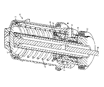
[0009] Fig. 1 is a perspective view of an automatic parking brake for a
body mounted
brake cylinder;
[0010] Fig. 2 is a cross-section of an automatic parking brake for a body
mounted
brake cylinder;
[0011] Fig. 3 is a perspective view of another automatic parking brake
for a body
mounted brake cylinder
[0012] Fig. 4 is a cross-section of the automatic parking brake for a
body mounted
brake cylinder seen in Fig. 3;
[0013] Fig. 5 is a perspective view of a further automatic parking brake
for a body
mounted brake cylinder;
[0014] Fig. 6 is a cross-section of the automatic parking brake for a
body mounted
brake cylinder see in Fig. 5;
[0015] Fig. 7 is a perspective view of the automatic parking brake for a
body mounted
brake cylinder seen in Figs. 5 and 6;
[0016] Fig. 8 is a perspective view of an additional automatic parking
brake for a
body mounted brake cylinder;
[0017] Fig. 9 is a cross-section of the automatic parking brake for a
body mounted
brake cylinder seen in Fig. 8;
[0018] Fig. 10 is a perspective view of the automatic parking brake for a
body
mounted brake cylinder seen in Figs. 8 and 9; and
[0019] Fig. 11 is a perspective view of the exterior of the automatic
parking brake for
a body mounted brake cylinder seen in Figs. 5 through 10.
DETAILED DESCRIPTION OF THE INVENTION
[0020] Referring now to the drawings, wherein like reference numerals
refer to like
parts throughout, there is seen in Figs. 1 and 2 a first embodiment of an
automatic parking
brake 10 interconnected to the non-pressure head of a body mounted brake
cylinder 12.
Brake cylinder 12 includes a piston 16 that moves in response to pneumatic
pressure applied
to an inlet 18, such as a source of brake cylinder pressure. A spring 20
biases piston 16 into a
brakes released position, and pressure applied to inlet 18 moves piston 16
into the brakes
applied position. A piston rod 14 is pushably coupled to the piston 16 at one
end and is
4
CA 02959725 2017-03-01
WO 2016/036798 PCT/US2015/048051
connected to the braking system at the other end to apply the brakes of a rail
car. A threaded
shaft 22 having a hollow cavity is also coupled to piston 16 and extends
axially around piston
rod 14 for movement therewith. Piston rod 14 connected to piston 16 such that
piston rod 14
is free to pivot relative to piston 16 within the bounds of the inside of
threaded shaft 22 to
accommodate angular misalignment of piston rod 14 as the brake lever of the
braking system
to which piston rod 14 in connected operates through an arc.
[0021] Threaded shaft 22 is selectively locked and unlocked by the action
of a
locking nut 24 positioned between two thrust bearings 26 and 28 and threaded
to shaft 22 via
high helix threads, and a locking sleeve 30 that is rotationally fixed but
free to move into and
out of engagement with locking nut 24. When engaged with nut 24, locking
sleeve 30
prevents nut 24 from rotating, and thereby locking shaft 22 in place. When
sleeve 30 is
disengaged from nut 24, nut 24 is free to rotate, thereby allowing shaft 22 to
translate
between the brakes applied and brakes released position. Sleeve 30 is biased
into
engagement with nut 24 and a pressure port 32, which is preferably connected
to a source of
brake pipe pressure, allows pressure to be applied directly to sleeve 30 to
move it out of
engagement with nut 24. As a result, the removal of brake pipe pressure after
the application
of brake cylinder pressure will automatically lock brake cylinder 12 in the
brakes applied
position, and the restoration of brake pipe pressure will release automatic
parking brake 10.
A pin 34 may be positioned between a shoulder 34 of sleeve 30 and nut 24 and,
more
particularly, in a groove formed in shaft 22, to prevent rotation of sleeve 30
about shaft 22. A
protective boot 36 may be positioned about the end of shaft 22 to protect
against outside
elements.
[0022] There is seen in Figs. 3 and 4 another embodiment of an automatic
parking
brake 110 interconnected to the non-pressure head of a body mounted brake
cylinder 112.
Brake cylinder 112 includes a piston 116 that moves in response to pneumatic
pressure
applied to an inlet 118, such as a source of brake cylinder pressure. A spring
120 biases
piston 116 into a brakes released position, and pressure applied to inlet 118
moves piston 116
into the brakes applied position. A threaded shaft 122 is coupled to the
piston 116 at one end
and is interconnected to the braking system at the other end via a connecting
rod 140 that is
connected to threaded shaft 122 by a ball joint 142. The push rod (not shown)
of a
conventional braking system may be positioned over connecting rod 140.
Threaded shaft 122
is selectively locked and unlocked by the action of a locking nut 124
positioned between two
thrust bearings 126 and 128 and threaded to shaft 120 via high helix threads,
and a locking
sleeve 130 that is rotationally fixed but free to move into and out of
engagement with locking
CA 02959725 2017-03-01
WO 2016/036798 PCT/US2015/048051
nut 124. When engaged with nut 124, locking sleeve 130 prevents nut 124 from
rotating, and
thereby locking shaft 120 in place. When sleeve 130 is disengaged from nut
124, nut 124 is
free to rotate, thereby allowing shaft 120 to translate between the brakes
applied and brakes
released position. Sleeve 130 is biased into engagement with nut 124 and a
pressure port
132, which is preferably connected to a source of brake pipe pressure.
Pressure port 132
allows pressure to be applied directed to sleeve 130 to move it out of
engagement with nut
124. As a result, the removal of brake pipe pressure after the application of
brake cylinder
pressure will automatically lock brake cylinder 112 in the brakes applied
position, and the
restoration of brake pipe pressure will release automatic parking brake 110. A
pair of pins
134 may positioned between a shoulder 134 of sleeve 130 and nut 124. A
protective boot
may be is positioned about shaft 122 to protect against outside elements.
[0023] There is seen in Figs. 5 through 7, another embodiment of an
automatic
parking brake 210 for a body mounted brake cylinder 212 having a pair of
locking assemblies
240 oriented symmetrically about the centerline of the push rod, thereby
preventing the piston
from tipping when the brake force is applied through locking assemblies 240.
Although a
configuration with two locking assemblies 240 is disclosed, any number greater
than one
could be utilized, provided that the locking assemblies 240 are oriented
symmetrically about
centerline of the push rod. Brake cylinder 212 includes a piston 216 that
moves in response
to pneumatic pressure applied to an inlet 218, such as a source of brake
cylinder pressure. A
spring 220 biases piston 216 into a brakes released position, and pressure
applied to inlet 218
moves piston 216 into the brakes applied position. A piston rod 214 is coupled
to the piston
216 at one end and is interconnected to the braking system at the other end.
[0024] Each locking assembly 240 comprises a threaded shaft 222 coupled
to piston
216 and positioned in parallel with piston rod 214. Threaded shaft 222 is
selectively locked
and unlocked by the action of a locking nut 224 that is threaded to shaft 222
via high helix
threads. A locking sleeve 230 is positioned proximately to locking nut 224 and
is rotationally
fixed but free to move axially into and out of engagement with locking nut
224. Locking nut
224 is held in place by a bushing 226 and a thrust bearing 228. Locking sleeve
230 is biased
into engagement with each locking nut 224 by a spring 232. When engaged with
nut 224,
locking sleeve 230 prevents nut 224 from rotating, and thereby locking shaft
222 in place.
When each sleeve 230 is disengaged from each nut 224, each nut 224 is free to
rotate, thereby
allowing each shaft 222 to translate between the brakes applied and brakes
released position.
Pins 234 may be used to prevent rotation of sleeve 230. Each locking assembly
240 may be
6
CA 02959725 2017-03-01
WO 2016/036798 PCT/US2015/048051
protected by a boot 256 positioned in covering relation to the cover 258
enclosing spring 232
in the non-pressure head 254 of brake cylinder 214.
[0025] The pair of locking assemblies 240 are interconnected to each
other by an
activating assembly 242 comprising a piston 244 having a tapered edge 246 in
contact with a
pair of pins 248 so that translation of piston 244 from a non-pressurized
position to a
pressurized position caused pins 248 move linearly outwardly as the tapered
edge 246
gradually pushes against pins 248. Pins 248 extend outwardly from tapered edge
246 of
piston 244 into contact with a pair of cams 250. Each cam 250 is mechanically
interconnected to each locking sleeve 230 of each locking assembly 240 by a
shoulder 252 on
the opposing end of cam 250 so that, when rotated, engages a corresponding
shoulder 254 on
locking sleeve 230 and moves locking sleeve 230 axially out of engagement with
locking nut
224. As a result, the linear movement of pins 248 in response to the movement
of piston 244
will cause cams 250 to rotate and the rotation of cams 250 will force locking
sleeves 230 to
move out of engagement with locking nuts 224. Thus, when a source of pressure
is applied
to or removed from a pressure port 262 associated with the face 260 of piston
244, such as
brake pipe pressure, locking assemblies 240 are unlocked or locked,
respectively. A manual
piston knob 264 may be coupled to piston 244 to allow for a manual application
or release of
locking assemblies 240.
[0026] There is seen in Figs. 8 through 10, another embodiment of an
automatic
parking brake 310 for a body mounted brake cylinder 312 having a pair of
locking assemblies
340. Brake cylinder 312 includes a piston 316 that moves in response to
pneumatic pressure
applied to an inlet 318, such as a source of brake cylinder pressure. A spring
320 biases
piston 316 into a brakes released position, and pressure applied to inlet 318
moves piston 316
into the brakes applied position. A piston rod 314 is coupled to the piston
316 at one end and
is interconnected to the braking system at the other end.
[0027] Each locking assembly 340 comprises a threaded shaft 322 coupled
to piston
316 and positioned in parallel with piston rod 314. Threaded shaft 322 is
selectively locked
and unlocked by the action of a locking nut 324 that is threaded to shaft 322
via high helix
threads. A locking sleeve 330 is positioned proximately to locking nut 324 and
is rotationally
fixed but free to move axially into and out of engagement with locking nut
324. Locking nut
324 is held in place by a bushing 326 and a thrust bearing 328. Locking sleeve
330 is biased
into engagement with each locking nut 324 by a spring 332 into a locked
position. When
engaged with nut 324, locking sleeve 330 prevents nut 324 from rotating, and
thereby locking
shaft 322 in place. When each sleeve 230 is disengaged from each nut 224, each
nut 224 is
7
CA 02959725 2017-03-01
WO 2016/036798 PCT/US2015/048051
free to rotate, thereby allowing each shaft 222 to translate between the
brakes applied and
brakes released position. Each locking assembly 340 may be protected by a boot
356
positioned in covering relation to the cover 358 enclosing spring 332 in the
non-pressure head
354 of brake cylinder 314. Pins 334 may be used to prevent rotation of sleeve
330.
[0028] The pair of locking assemblies 340 are interconnected to each
other by an
activating assembly 342 comprising a piston 344 that can selectively apply
pressure via a pair
of conduits 346 directly to locking sleeves 330 to move them out of engagement
with the
corresponding locking nuts 324. Piston 344 is preferably biased so that no
pressure is
supplied to locking sleeves 330 and may be automatically actuated, such as by
connecting a
source of brake pipe pressure, or by providing a manual point of connection to
the face 360 of
piston 344. Referring to Fig. 10, piston 344 may include a manual release nut
350 that, when
rotating, will withdraw piston 344 so that pressure is applied to locking
sleeve 330 to move
into the disengaged position relative to locking nut 324 so that brake piston
316 may return to
the brakes released position. Piston 344 may include one or more 0-rings 352
to seal piston
344 within the non-pressure head 354 of brake cylinder 314. Fig. 11 shows the
outer
structure of a brake cylinder according to Figs. 5 through 7, or 8 through 10.
8