Sélection de la langue

Search

Sommaire du brevet 2961339 

Énoncé de désistement de responsabilité concernant l'information provenant de tiers

Une partie des informations de ce site Web a été fournie par des sources externes. Le gouvernement du Canada n'assume aucune responsabilité concernant la précision, l'actualité ou la fiabilité des informations fournies par les sources externes. Les utilisateurs qui désirent employer cette information devraient consulter directement la source des informations. Le contenu fourni par les sources externes n'est pas assujetti aux exigences sur les langues officielles, la protection des renseignements personnels et l'accessibilité.

Disponibilité de l'Abrégé et des Revendications

L'apparition de différences dans le texte et l'image des Revendications et de l'Abrégé dépend du moment auquel le document est publié. Les textes des Revendications et de l'Abrégé sont affichés :

  • lorsque la demande peut être examinée par le public;
  • lorsque le brevet est émis (délivrance).
(12) Brevet: (11) CA 2961339
(54) Titre français: DISPOSITIF DE VERROUILLAGE EN ARCEAU DOTE D'ELEMENTS ANTI-ROTATION
(54) Titre anglais: HOOP LOCK WITH ANTI-ROTATION FEATURES
Statut: Accordé et délivré
Données bibliographiques
(51) Classification internationale des brevets (CIB):
  • E05B 67/22 (2006.01)
(72) Inventeurs :
  • KINDSTRAND, DANIEL HUGH (Etats-Unis d'Amérique)
  • KUMAR, HASSAN CHARAN (Inde)
  • RAMAKRISHNA, MANJUNATHA (Inde)
  • MILLER, DAVID BRUCE (Etats-Unis d'Amérique)
(73) Titulaires :
  • SCHLAGE LOCK COMPANY LLC
(71) Demandeurs :
  • SCHLAGE LOCK COMPANY LLC (Etats-Unis d'Amérique)
(74) Agent: FASKEN MARTINEAU DUMOULIN LLP
(74) Co-agent:
(45) Délivré: 2019-08-27
(86) Date de dépôt PCT: 2015-08-24
(87) Mise à la disponibilité du public: 2016-02-25
Requête d'examen: 2017-03-14
Licence disponible: S.O.
Cédé au domaine public: S.O.
(25) Langue des documents déposés: Anglais

Traité de coopération en matière de brevets (PCT): Oui
(86) Numéro de la demande PCT: PCT/US2015/046572
(87) Numéro de publication internationale PCT: US2015046572
(85) Entrée nationale: 2017-03-14

(30) Données de priorité de la demande:
Numéro de la demande Pays / territoire Date
62/040,929 (Etats-Unis d'Amérique) 2014-08-22

Abrégés

Abrégé français

Un cerceau verrou comprenant une manille et une barre transversale, la manille comportant une paire de pattes s'étendant à partir d'une partie corps, et chacune des pattes comportant un pied comprenant une pointe ayant une section transversale non circulaire. La barre transversale comprend un boîtier comportant une paire d'ouvertures de réception de pied et une paire d'ouvertures de réception de pointe sensiblement alignées sur les ouvertures de réception de pied. Les ouvertures de réception de pointe sont conçues pour entrer en prise d'accouplement avec les pointes de telle sorte que les pointes soient accouplées rotatives au boîtier.


Abrégé anglais

A hoop lock including a shackle and a crossbar, with the shackle having a pair of legs extending from a body portion, and each of the legs having a foot including a tip with a non- circular cross-section. The cross-bar includes a housing having a pair of foot-receiving openings and a pair of tip-receiving openings substantially aligned with foot-receiving openings. The tip- receiving openings are configured to matingly engage the tips such that the tips are rotationally coupled to the housing.

Revendications

Note : Les revendications sont présentées dans la langue officielle dans laquelle elles ont été soumises.


WHAT IS CLAIMED IS:
1. An apparatus, comprising:
a shackle comprising:
a body portion;
a first leg extending from the body portion and including a first foot; and
a second leg extending from the body portion and including a second foot
arranged parallel to the first foot; and
wherein each foot comprises:
a distal tip portion having a non-circular outer cross-section including a
pair of parallel engagement surfaces connected by a pair of arcuate surfaces;
a cylindrical portion having a circular outer cross section; and
a groove defined in the cylindrical portion; and
a cross bar comprising:
a tubular housing including:
an internal cavity;
a pair of foot-receiving openings sized and configured to receive the
cylindrical portions of the first and second feet;
a pair of tip-receiving openings aligned with the pair of foot-receiving
openings and sized and configured to receive the distal tip portions of the
first and second feet;
and
a lock mechanism including a pair of deadbolts positioned in the housing, the
lock
mechanism having a locked state in which each deadbolt is engaged with the
groove of a
corresponding one of the feet and retains the corresponding foot within the
housing, and an
unlocked state in which the deadbolts do not prevent removal of the feet from
the housing.
2. The apparatus of claim 1, wherein the pair of parallel engagement
surfaces are
arranged substantially parallel to a depth dimension of the groove.
3. The apparatus of claim 1, wherein the pair of parallel engagement
surfaces are
arranged substantially perpendicular to a depth dimension of the groove.
9

4. The apparatus of claim 1, wherein the shackle is substantially U-shaped.
5. The apparatus of claim 1, wherein the lock mechanism comprises at least
one of a
key-operable lock cylinder and a combination lock mechanism.
6. The apparatus of claim 1, wherein the pair of engagement surfaces
extends from a
first of the arcuate surfaces to a second of the arcuate surfaces.
7. The apparatus of claim 1, wherein the pair of engagement surfaces are
offset from
a center point of the distal tip portion by substantially the same distance.
8. The apparatus of claim 1, wherein each of the tip-receiving openings has
a
geometry corresponding to the non-circular cross-section of the distal tip
portion.
9. The apparatus of claim 1, wherein each of the tip-receiving openings is
sized and
configured to matingly engage each of the distal tip portions of the first and
second feet.
10. The apparatus of claim 1, wherein the distal tip portions of the first
and second
feet are mirror images of one another.
11 The apparatus of claim 1, wherein the tip-receiving openings are
mirror images of
one another.
12. An apparatus, comprising:
a shackle comprising a pair of legs having equal lengths, each leg including a
foot portion
having an outer cross-section and defining a groove;
a tubular cross-bar extending in a longitudinal direction, the cross-bar
including a pair of
openings, each of the openings sized and shaped to receive the foot portion of
a corresponding
one of the legs, the cross-bar including an internal cavity in communication
with the openings,
wherein the openings are offset from one another in the longitudinal
direction, and wherein each
of the openings has an inner cross-section corresponding to the outer cross-
section of the foot
portion of the corresponding leg; and

a lock mechanism positioned in the internal cavity of the cross-bar and
including a pair of
deadbolts, the lock mechanism having a locked state in which each deadbolt is
engaged with the
groove of a corresponding one of foot portions and retains the corresponding
foot portion in
engagement with the cross-bar, and an unlocked state in which the deadbolts do
not prevent
removal of the foot portion from the cross-bar; and
wherein the outer cross-section of each foot portion and the inner cross-
section of each
opening in the cross-bar includes a pair of straight portions and a pair of
curved portions
connecting the pair of straight portions.
13. The apparatus of claim 12, wherein each of the curved portions has a
first end and
a second end, one of the straight portions connects the first ends of the
curved portions, and the
other of the straight portions connects the second ends of the curved
portions.
14. The apparatus of claim 12, wherein the pair of straight portions are
arranged
parallel with one another.
15. An apparatus, comprising:
a shackle comprising:
a body portion;
a first leg extending from the body portion and including a first foot; and
a second leg extending from the body portion and including a second foot;
wherein each foot comprises:
a tip portion having a non-circular outer cross-section; and
a groove; and
a tubular housing extending in a longitudinal direction and including:
an internal cavity;
a pair of first openings offset from one another in the longitudinal direction
and sized
and configured to receive the first and second feet; and
a pair of second openings offset from one another in the longitudinal
direction and
sized and configured to receive the tip portions of the first and second feet,
each of the second
openings having a non-circular inner cross section corresponding to the non-
circular outer cross
11

section of the tip portions;
wherein the first and second feet extend through the pair of first openings
such that
the tip portions are received in the second openings; and
a lock mechanism including a pair of deadbolts positioned in the housing, the
lock
mechanism having a locked state in which each deadbolt is engaged with the
groove of a
corresponding one of the feet and retains the corresponding foot within the
housing, and an
unlocked state in which the deadbolts do not prevent removal of the feet from
the housing.
16. The apparatus of claim 15, wherein the non-circular outer cross-section
of each tip
portion comprises an arcuate segment and at least one additional segment.
17. The apparatus of claim 16, wherein the at least one additional segment
comprises at
least one straight segment.
18. The apparatus of claim 17, wherein the at least one straight segment
comprises a first
straight segment and a second straight segment.
19. The apparatus of claim 18, wherein the non-circular outer cross-section
of each tip
portion further comprises a second arcuate segment, wherein the first straight
segment and the
second straight segment connect the arcuate segment and the second arcuate
segment.
20. The apparatus of claim 18, wherein the first straight segment and the
second straight
segment are angled relative to one another.
21. The apparatus of claim 18, wherein the first straight segment and the
second straight
segment meet at a vertex.
22. The apparatus of claim 16, wherein the at least one additional segment
is at least one
curved segment.
12

23. The apparatus of claim 15, wherein the outer cross-section of each tip
portion is
crescent-shaped.
24. The apparatus of claim 15, wherein the outer cross-section of each tip
portion is D-
shaped.
25. The apparatus of claim 15, wherein each foot further comprises a
cylindrical portion
having a circular outer cross-section; and
wherein the cylindrical portions of the feet are received in the pair of first
openings.
26. An apparatus, comprising:
a shackle comprising a pair of legs, each leg including a foot portion
defining a groove and
a tip having an outer cross-section;
a tubular cross-bar extending in a longitudinal direction, the cross-bar
including a pair of
first openings and a pair of second openings, the cross-bar including an
internal cavity in
communication with the openings, wherein the first openings are offset from
one another in the
longitudinal direction and the legs extend through the first openings, wherein
the second openings
are offset from one another in the longitudinal direction and the tip of each
foot portion is received
in a corresponding and respective one of the second openings, and wherein each
of the second
openings has an inner cross-section corresponding to the outer cross-section
of the tip of the
corresponding leg; and
a lock mechanism positioned in the internal cavity of the cross-bar and
including a pair of
deadbolts, the lock mechanism having a locked state in which each deadbolt is
engaged with the
groove of a corresponding one of foot portions and retains the corresponding
foot portion in
engagement with the cross-bar, the lock mechanism having an unlocked state in
which the deadbolts
do not prevent removal of the foot portion from the cross-bar; and
wherein the outer cross-section of each tip and the inner cross-section of
each second
opening in the cross-bar has a non-circular shape.
27. The apparatus of claim 26, wherein each of the second openings in the
cross-bar has
13

a size and shape corresponding to the outer cross-section of the corresponding
tip.
28. The apparatus of claim 27, wherein the outer cross-section of each tip
portion is
either crescent-shaped or D-shaped.
29. An apparatus, comprising:
a shackle comprising a pair of feet, each foot including a tip portion having
a non-circular
outer cross-section;
a cross-bar extending along a longitudinal axis, the cross-bar comprising:
an internal cavity extending along the longitudinal axis;
a pair of first openings, wherein the pair of first openings are
longitudinally offset
from one another; and
a pair of second openings, wherein the pair of second openings are
longitudinally
offset from one another and are positioned diametrically opposite the pair of
first openings, wherein
each of the second openings has a non-circular inner cross-section
corresponding to the non-circular
outer cross-section such that the second openings are sized and shaped to
matingly receive the tip
portions of the feet; and
a lock mechanism positioned in the internal cavity and comprising a pair of
deadbolts, the
lock mechanism having a locking state in which the deadbolts prevent removal
of the feet from the
cross-bar, the locking mechanism having an unlocked state in which the
deadbolts do not prevent
removal of the feet from the cross-bar;
wherein the non-circular outer cross-section of each tip portion is either
crescent-shaped or
D-shaped; and
wherein the pair of feet are operable to extend through the pair of first
openings such that the
tip portions are received in the second openings.
14

Description

Note : Les descriptions sont présentées dans la langue officielle dans laquelle elles ont été soumises.


HOOP LOCK WITH ANTI-ROTATION FEATURES
[0001] TECHNICAL FIELD
[0002] The present invention generally relates to hoop locks, and more
particularly, but not
exclusively, to hoop locks having a removable shackle.
BACKGROUND
[0003] Hoop locks are commonly used to secure a portable object such as a
bicycle to a
stationary object such as a rack. These types of hoop locks are sometimes
referred to as shackle
locks, U-locks, or bicycle locks. Some locks of this type have certain
limitations, such as those
relating to resistance to tampering and attack. Therefore, a need remains for
further
improvements and developments in this area of technology.
SUMMARY
[0004] An exemplary hoop lock includes a shackle and a crossbar. The
shackle includes a pair
of legs extending from a body portion. Each of the legs includes a foot
comprising a tip with a
non-circular cross-section. The cross-bar comprises a housing including a pair
of foot-receiving
openings, and a pair of tip-receiving openings aligned with the foot-receiving
openings. The tip-
receiving openings are configured to matingly engage the tips such that the
tips are rotationally
coupled to the housing. Further embodiments, forms, features, and aspects of
the present
application shall become apparent from the description and figures provided
herewith.
1
CA 2961339 2018-07-23

CA 02961339 2017-03-14
WO 2016/029212 PCT/US2015/046572
BRIEF DESCRIPTION OF THE FIGURES
[0005] FIG. 1 is a cross-sectional illustration of a hoop lock including a
shackle according to one
embodiment.
[0006] FIG. 2 is a perspective illustration of a portion of the hoop lock
illustrated in FIG. 1.
[0007] FIG. 3 is a perspective illustration of a distal end portion or foot
of the shackle illustrated
in FIG. 1.
[0008] FIG. 4 is an end view of the distal tip of the foot illustrated in
FIG. 3.
[0009] FIG. 5 is a perspective illustration of a distal end portion or foot
of a shackle according to
another embodiment.
[0010] FIG. 6 is an end view of the distal tip of the foot illustrated in
FIG. 5.
[0011] FIG. 7 is a perspective illustration of a distal end portion or foot
of a shackle according to
another embodiment.
[0012] FIG. 8 is an end view of the distal tip of the foot illustrated in
FIG. 7.
[0013] FIG. 9 is a perspective illustration of a distal end portion or foot
of a shackle according to
another embodiment.
[0014] FIG. 10 is an end view of the distal tip of the foot illustrated in
FIG. 9.
[0015] FIG. 11 is a perspective illustration of a distal end portion or
foot of a shackle according
to another embodiment.
[0016] FIG. 12 is an end view of the distal tip of the foot illustrated in
FIG. 11.
[0017] FIGS. 13a and 13b respectively illustrate an end view and a side
view of a distal tip of the
foot of a shackle according to another embodiment.
[0018] FIGS. 14a and 14b respectively illustrate an end view and a side
view of a distal tip of the
foot of a shackle according to another embodiment.
[0019] FIGS. 15a and 15b respectively illustrate an end view and a side
view of a distal tip of the
foot of a shackle according to another embodiment.
[0020] FIGS. 16a and 16b respectively illustrate an end view and a side
view of a distal tip of the
foot of a shackle according to another embodiment.
2

CA 02961339 2017-03-14
WO 2016/029212 PCT/US2015/046572
DETAILED DESCRIPTION OF ILLUSTRATIVE EMBODIMENTS
[0021] For the purposes of promoting an understanding of the principles of
the invention,
reference will now be made to the embodiments illustrated in the drawings and
specific language
will be used to describe the same. It will nevertheless be understood that no
limitation on the
scope of the invention is hereby intended. Any alterations and further
modifications in the
described embodiments, and any further applications of the principles of the
invention as
described herein are contemplated as would normally occur to one skilled in
the art to which the
invention relates.
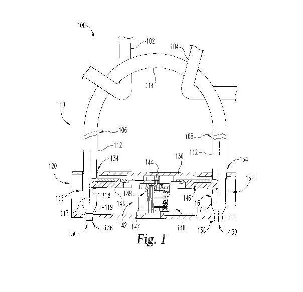
[0022] With reference to FIGS. 1 and 2, a hoop lock 100 according to one
embodiment generally
comprises a shackle 110 and a crossbar 120, which includes a housing 130 and a
locking
mechanism 140. As described in further detail below, the shackle 110 and
crossbar 120 are
separable, and the locking mechanism 140 is configured to selectively secure
the crossbar 120 to
the shackle 110. The lock 100 may be used to secure a first object 102 to a
second object 104
such as, for example, to prevent unauthorized separation or theft of the
objects 102, 104.
[0023] The illustrative shackle 110 includes a pair of legs 112 extending
from opposite ends of a
central body 114. In the illustrated form, the legs 112 are arranged
substantially parallel to one
another, and the central body 114 is curved or arcuate-shaped such that the
shackle 110 is
substantially U-shaped. However, it is also contemplated that the shackle 110
may take on
another shape or configuration. For example, the central body 114 may be
substantially
rectilinear, or portions of the legs 112 may be obliquely offset from one
another.
[0024] Each of the legs 112 comprises a foot 116, and the feet 116 are
arranged substantially
parallel to one another. Each foot 116 includes cylindrical portion 117, a
groove 118 formed in
the cylindrical portion 117, and a tip 150. One or both of the legs 112 may
include a
frusto conical tapered portion 119 connecting the cylindrical portion 117 to
the corresponding tip
150. When the shackle 110 is coupled to the crossbar 120, each foot 116 is
positioned in the
housing 130. While other geometries are contemplated, the illustrated legs
112, feet 116, and
tapered portions 119 each have a substantially circular cross-section. Each of
the tips 150,
however, has a non-circular cross-section, as will be illustrated and
described in further detail
below.
[0025] The exemplary housing 130 is configured as a tube defining an
internal cavity 132 in
which the locking mechanism 140 is positioned and seated. The housing 130
includes a pair of
3

CA 02961339 2017-03-14
WO 2016/029212 PCT/US2015/046572
foot-receiving openings 134 and a pair of tip-receiving openings 136 aligned
with the foot-
receiving openings 136. The foot-receiving openings 134 are sized and
configured to receive the
feet 116, and the tip-receiving openings 136 are sized and configured to
receive the tips 150. As
illustrated in FIG. 2, when the shackle 110 is coupled to the crossbar 120,
the tips 150 are
positioned or seated in the tip-receiving openings 136.
[0026] The locking mechanism 140 is configured to secure the shackle 110 to
the crossbar 120
in a locked state, and to permit separation of the shackle 110 and the
crossbar 120 in an unlocked
state. The illustrative locking mechanism 140 generally includes a lock
cylinder 142, a cam 144
connected to the lock cylinder 142, and a pair of deadbolts 146 engaged with
the cam 144. The
lock cylinder 142 includes a shell 147 coupled to the housing 130, and a
spindle 148 which is
rotatable with respect to the shell 147 upon insertion of a proper key 149
(FIG. 2). The cam 144
is rotationally coupled with the spindle 148, and is configured to extend and
retract the deadbolts
146 in response to rotation of the spindle 148. While the illustrated lock
mechanism 140
includes a key-operable lock cylinder 142, it is also contemplated that other
forms of lock
mechanism may be utilized. For example, in certain embodiments, the lock
mechanism 140 may
include a combination lock mechanism in addition to or in lieu of the lock
cylinder 142.
[0027] In FIG. 1, the deadbolts 146 are positioned in an extended position
and are engaged with
the feet 116. More specifically, the end of each deadbolt 146 is received in
the groove 118 of
one of the feet 116. With the deadbolts 146 engaged with the feet 116, the
shackle 110 cannot be
removed from the crossbar 120, thereby defining the locked state. When the key
149 is inserted
and the spindle 148 is rotated, the cam 144 retracts the deadbolts 146 to a
retracted position. In
the retracted position, the deadbolts 146 do not engage the feet 116, and the
shackle 110 can be
separated from the crossbar 120, thereby defining the unlocked state.
[0028] With additional reference to FIGS. 3 and 4, each tip 150 extends
from a base 151 to an
end surface 152. The base 151 is defined by the terminus of the tapered
portion 119, and is
substantially circular about a center point 153. As illustrated in FIG. 4,
each tip 150 has a non-
circular cross-sectional geometry, and each tip-receiving opening 136 has a
geometry
corresponding to that of the tip 150. In the illustrated form, the tip 150
includes a flat
engagement surface 154 and a curved or arcuate side surface 156 which defines
a segment of a
circle formed about the center point 153. The engagement surface 154 may, for
example, define
a 45 angle with respect to two perpendicular radii of the arcuate surface
156. While the
4

CA 02961339 2017-03-14
WO 2016/029212 PCT/US2015/046572
illustrated engagement surface 154 is obliquely offset with respect to a depth
dimension of the
groove 118, it is also contemplated that the engagement surface 154 may be
arranged parallel or
perpendicular to the depth dimension of the groove 118.
[0029] During manufacture, the tip 150 may initially be configured as a
substantially cylindrical
tip extending from the circular base 151. The engagement surface 154 may be
formed by milling
or machining away a portion of the cylindrical tip. For example, a milling bit
may be passed
along a straight line offset from and arranged parallel to a diameter of the
base 151.
[0030] With specific reference to FIGS. 2 and 4, when the shackle 110 is
coupled to the crossbar
120, the non-circular tips 150 are received in the tip-receiving openings 136.
The tip-receiving
openings 136 are configured to receive and matingly engage the tips 150 such
that the tips 150
are rotationally coupled to the housing 130. Each of the tip-receiving
openings 136 may have a
geometry corresponding to the non-circular cross-section of the tip 150. As
illustrated in FIG. 4,
each tip-receiving opening 136 includes a flat engagement edge 137
corresponding to the flat
engagement surface 154, and a curved or arcuate edge 138 corresponding to the
curved or
arcuate side surface 156. The tip-receiving openings 136 and the tips 150 may
be configured
such that each tip-receiving opening 136 is capable of receiving each of the
tips 150, thereby
enabling the shackle 110 to be coupled to the crossbar 120 in either of two
orientations. For
example, the tip-receiving openings 136 may be mirror images of one another,
and the tips 150
may likewise be mirror images of one another.
[0031] A common form of attempting to defeat a hoop lock (such as the lock
100) is to cut
through one of the legs 112, as depicted by the cut 106 illustrated in FIG. 1.
Once the leg 112 is
cut, the attacker manually rotates the uncut leg 112, using the central body
114 as a lever arm. If
the central body 114 is sufficiently rotated, a gap forms at the cut 106,
thereby allowing one or
both of the objects 102, 104 to be removed from the shackle 110 through the
gap. While the
deadbolts of conventional hoop locks resist rotation of the legs, it has been
found that certain
conventional systems remain susceptible to the above-described type of cut
attack.
[0032] With the shackle 110 coupled to the crossbar 120 as described above,
engagement
between the tip-receiving openings 136 and the tips 150 rotationally couples
the feet 116 to the
housing 130. As a result, the crossbar 120 substantially prevents rotation of
the legs 112, thereby
preventing formation of the above-described gap. The term "substantially" as
used herein may
be applied to modify a quantitative representation which could permissibly
vary without

CA 02961339 2017-03-14
WO 2016/029212 PCT/US2015/046572
resulting in a change in the basic function to which it relates. For example,
with the tip 150
engaged with the tip-receiving opening 136, the leg 116 may permissibly be
capable of slight
rotation if the above-described gap formation is prevented. With the legs 112
unable to rotate,
the attacker must make a second cut 108 in the shackle 110 such that a portion
of the shackle 110
can be removed to form a gap through which the objects 102, 104 can be passed.
[0033] FIGS. 5-10 depict tip-receiving openings and feet including tips
according to other
embodiments. The tip-receiving openings, feet, and tips are shaped and
configured substantially
similar to the tip-receiving openings 136, feet 116 and tips 150. Unless
indicated otherwise,
similar reference characters are used to indicate similar elements and
features. In the interest of
conciseness, the following descriptions focus primarily on features that are
different than those
described above with regard to the tip-receiving openings 136, feet 116 and
tips 150.
[0034] With reference to FIGS. 5 and 6, a tip 250 according to one
embodiment includes a
curved or arcuate side surface 256 and a concave arcuate engagement surface
254. The tip-
receiving opening 236 has a geometry corresponding to that of the tip 250, and
includes a convex
engagement edge 237 corresponding to the concave engagement surface 254. In
the illustrated
form, the arcuate engagement surface 254 has an arc radius greater than that
of the arcuate side
surface 256. In other embodiments, the arc radius of the concave engagement
surface 254 may
be equal to or less than that of the arcuate side surface 256. Additionally,
while the exemplary
engagement surface 254 is formed on the opposite side of the center point 253
as the groove 218,
it is also contemplated that the engagement surface may be oriented and
arranged in another
manner.
[0035] During manufacture, the tip 250 may begin as a substantially
cylindrical tip having a
circular cross-section corresponding to that of the base 251, and the
engagement surface 254 may
be formed by milling or machining away a portion of the cylindrical tip. For
example, a milling
bit may be passed along a straight line toward the center point 253 such that
the engagement
surface 254 has a radius of curvature corresponding to the radius of the
milling bit.
[0036] With reference to FIGS. 7 and 8, a tip 350 according to another
embodiment includes a
convex engagement surface 354 which has an arc radius greater than that of the
arcuate side
surface 356. The tip-receiving opening 336 is defined, in part, by a concave
engagement edge
337 corresponding to the convex engagement surface 354.
6

CA 02961339 2017-03-14
WO 2016/029212 PCT/US2015/046572
[0037] With reference to FIGS. 9 and 10, a tip 450 according to another
embodiment includes a
pair of flat engagement surfaces 454 that join or intersect one another at a
vertex 455. The tip-
receiving opening 436 likewise includes a pair of engagement edges 437 joining
one another at a
vertex. While the illustrated engagement surfaces 454 are arranged
substantially perpendicular
to one another, it is also contemplated that the engagement surfaces 454 may
be offset from one
another at an oblique angle. In such forms, the engagement edges 437 may be
offset from one
another at a substantially equivalent oblique angle.
[0038] With reference to FIGS. 11 and 12, a tip 550 according to another
embodiment includes a
pair of engagement surfaces 554 and a pair of curved or arcuate side surfaces
556 connecting the
engagement surfaces 554. The tip-receiving opening 536 likewise includes a
pair of flat
engagement edges 537 and a pair of arcuate edges 538 connecting the engagement
edges 537. In
the illustrated form, the engagement surfaces 554 are obliquely offset from
one another. In other
embodiments, two or more flat engagement surfaces may be arranged parallel
with or
perpendicular to one another, and at least some of the flat engagement
surfaces may be formed
adjacent the curved or arcuate side surfaces.
[0039] FIGS. 13-16 depict feet including tips according to further
embodiments. Each of the
feet is configured substantially similar to the feet 116, and each of the tips
is configured
substantially similar to the tips 150. Unless indicated otherwise, similar
reference characters are
used to indicate similar elements and features. In the interest of
conciseness, the following
descriptions focus primarily on features that are different than those
described above with regard
to the feet 116 and tips 150. While not specifically illustrated, it should be
understood that a tip-
receiving opening in each of the embodiments described hereinafter may have a
shape
corresponding to that of the tip.
[0040] With reference to FIGS. 13a and 13b, a tip 650 according to another
embodiment
includes four flat engagement surfaces 654. Each of the engagement surfaces
654 is arranged
either parallel or perpendicular to a depth dimension of the groove 618 such
that the face 652 is
substantially square-shaped. Additionally, the tip 650 is positioned and
arranged generally
concentric with the foot 616, and the greatest dimension of the face 652 is
less than the diameter
of the foot 616.
[0041] With reference to FIGS. 14a and 14b, a tip 750 according to another
embodiment
includes four flat engagement surfaces 754. Each of the engagement surfaces
754 is angularly
7

CA 02961339 2017-03-14
WO 2016/029212 PCT/US2015/046572
offset, for example, by about 45 with respect to a depth dimension of the
groove 718, thereby
resulting in a face 752 that is diamond-shaped. Additionally, the greatest
dimension of the face
752 is substantially equal to the diameter of the foot 716 such that the
diamond-shaped face 752
is circumscribed by the circular cross-section of the foot 716.
[0042] With reference to FIGS. 15a and 15b, a tip 850 according to another
embodiment
includes four flat engagement surfaces 854. Each of the engagement surfaces
854 is arranged
either parallel or perpendicular to a depth dimension of the groove 818 such
that the face 852 is
substantially square-shaped. Additionally, the greatest dimension of the face
852 is substantially
equal to the diameter of the foot 816 such that the square-shaped face 852 is
circumscribed by
the circular cross-section of the foot 816.
[0043] With reference to FIGS. 16a and 16b, a tip 950 according to another
embodiment
includes a pair of parallel engagement surfaces 952 connected by a pair of
curved or arcuate
surfaces 954. In the illustrated form, the engagement surfaces 952 are
arranged substantially
parallel to the depth dimension of the groove 918. In other embodiments, the
engagement
surfaces 952 may be arranged substantially perpendicular to or obliquely
offset with respect to
the depth dimension of the groove 918.
[0044] While the invention has been illustrated and described in detail in
the drawings and
foregoing description, the same is to be considered as illustrative and not
restrictive in character,
it being understood that only the preferred embodiments have been shown and
described and that
all changes and modifications that come within the spirit of the inventions
are desired to be
protected.
[0045] It should be understood that while the use of words such as
preferable, preferably,
preferred or more preferred utilized in the description above indicate that
the feature so described
may be more desirable, it nonetheless may not be necessary and embodiments
lacking the same
may be contemplated as within the scope of the invention, the scope being
defined by the claims
that follow. In reading the claims, it is intended that when words such as
"a," "an," "at least
one," or "at least one portion" are used there is no intention to limit the
claim to only one item
unless specifically stated to the contrary in the claim. When the language "at
least a portion"
and/or "a portion" is used the item can include a portion and/or the entire
item unless specifically
stated to the contrary.
8

Dessin représentatif
Une figure unique qui représente un dessin illustrant l'invention.
États administratifs

2024-08-01 : Dans le cadre de la transition vers les Brevets de nouvelle génération (BNG), la base de données sur les brevets canadiens (BDBC) contient désormais un Historique d'événement plus détaillé, qui reproduit le Journal des événements de notre nouvelle solution interne.

Veuillez noter que les événements débutant par « Inactive : » se réfèrent à des événements qui ne sont plus utilisés dans notre nouvelle solution interne.

Pour une meilleure compréhension de l'état de la demande ou brevet qui figure sur cette page, la rubrique Mise en garde , et les descriptions de Brevet , Historique d'événement , Taxes périodiques et Historique des paiements devraient être consultées.

Historique d'événement

Description Date
Requête pour le changement d'adresse ou de mode de correspondance reçue 2020-01-17
Représentant commun nommé 2019-10-30
Accordé par délivrance 2019-08-27
Inactive : Page couverture publiée 2019-08-26
Requête pour le changement d'adresse ou de mode de correspondance reçue 2019-08-14
Inactive : Lettre officielle 2019-07-19
Un avis d'acceptation est envoyé 2019-07-19
Inactive : Approuvée aux fins d'acceptation (AFA) 2019-07-05
Inactive : Q2 réussi 2019-07-05
Lettre envoyée 2019-06-28
Préoctroi 2019-06-19
Retirer de l'acceptation 2019-06-19
Taxe finale payée et demande rétablie 2019-06-19
Inactive : Taxe finale reçue 2019-06-19
Requête en rétablissement reçue 2019-06-19
Modification reçue - modification volontaire 2019-06-19
Réputée abandonnée - les conditions pour l'octroi - jugée non conforme 2019-04-17
Lettre envoyée 2018-10-17
Un avis d'acceptation est envoyé 2018-10-17
Inactive : Q2 réussi 2018-10-15
Inactive : Approuvée aux fins d'acceptation (AFA) 2018-10-15
Modification reçue - modification volontaire 2018-07-23
Inactive : Dem. de l'examinateur par.30(2) Règles 2018-02-01
Inactive : Rapport - Aucun CQ 2018-01-29
Inactive : Page couverture publiée 2017-08-17
Modification reçue - modification volontaire 2017-05-19
Inactive : Acc. récept. de l'entrée phase nat. - RE 2017-03-29
Lettre envoyée 2017-03-28
Inactive : CIB en 1re position 2017-03-23
Inactive : CIB attribuée 2017-03-23
Demande reçue - PCT 2017-03-23
Exigences pour l'entrée dans la phase nationale - jugée conforme 2017-03-14
Exigences pour une requête d'examen - jugée conforme 2017-03-14
Toutes les exigences pour l'examen - jugée conforme 2017-03-14
Demande publiée (accessible au public) 2016-02-25

Historique d'abandonnement

Date d'abandonnement Raison Date de rétablissement
2019-06-19
2019-04-17

Taxes périodiques

Le dernier paiement a été reçu le 2019-07-23

Avis : Si le paiement en totalité n'a pas été reçu au plus tard à la date indiquée, une taxe supplémentaire peut être imposée, soit une des taxes suivantes :

  • taxe de rétablissement ;
  • taxe pour paiement en souffrance ; ou
  • taxe additionnelle pour le renversement d'une péremption réputée.

Les taxes sur les brevets sont ajustées au 1er janvier de chaque année. Les montants ci-dessus sont les montants actuels s'ils sont reçus au plus tard le 31 décembre de l'année en cours.
Veuillez vous référer à la page web des taxes sur les brevets de l'OPIC pour voir tous les montants actuels des taxes.

Historique des taxes

Type de taxes Anniversaire Échéance Date payée
Rétablissement (phase nationale) 2017-03-14
Taxe nationale de base - générale 2017-03-14
Requête d'examen - générale 2017-03-14
TM (demande, 2e anniv.) - générale 02 2017-08-24 2017-03-14
TM (demande, 3e anniv.) - générale 03 2018-08-24 2018-07-25
Taxe finale - générale 2019-06-19
Rétablissement 2019-06-19
TM (demande, 4e anniv.) - générale 04 2019-08-26 2019-07-23
TM (brevet, 5e anniv.) - générale 2020-08-24 2020-07-21
TM (brevet, 6e anniv.) - générale 2021-08-24 2021-07-21
TM (brevet, 7e anniv.) - générale 2022-08-24 2022-07-21
TM (brevet, 8e anniv.) - générale 2023-08-24 2023-07-21
Titulaires au dossier

Les titulaires actuels et antérieures au dossier sont affichés en ordre alphabétique.

Titulaires actuels au dossier
SCHLAGE LOCK COMPANY LLC
Titulaires antérieures au dossier
DANIEL HUGH KINDSTRAND
DAVID BRUCE MILLER
HASSAN CHARAN KUMAR
MANJUNATHA RAMAKRISHNA
Les propriétaires antérieurs qui ne figurent pas dans la liste des « Propriétaires au dossier » apparaîtront dans d'autres documents au dossier.
Documents

Pour visionner les fichiers sélectionnés, entrer le code reCAPTCHA :


Pour visualiser une image, cliquer sur un lien dans la colonne description du document (Temporairement non-disponible). Pour télécharger l'image (les images), cliquer l'une ou plusieurs cases à cocher dans la première colonne et ensuite cliquer sur le bouton "Télécharger sélection en format PDF (archive Zip)" ou le bouton "Télécharger sélection (en un fichier PDF fusionné)".

Liste des documents de brevet publiés et non publiés sur la BDBC .

Si vous avez des difficultés à accéder au contenu, veuillez communiquer avec le Centre de services à la clientèle au 1-866-997-1936, ou envoyer un courriel au Centre de service à la clientèle de l'OPIC.

({010=Tous les documents, 020=Au moment du dépôt, 030=Au moment de la mise à la disponibilité du public, 040=À la délivrance, 050=Examen, 060=Correspondance reçue, 070=Divers, 080=Correspondance envoyée, 090=Paiement})


Description du
Document 
Date
(aaaa-mm-jj) 
Nombre de pages   Taille de l'image (Ko) 
Description 2017-03-13 8 444
Revendications 2017-03-13 4 122
Dessins 2017-03-13 9 110
Abrégé 2017-03-13 2 70
Dessin représentatif 2017-03-13 1 15
Revendications 2017-05-18 3 103
Description 2018-07-22 8 447
Revendications 2018-07-22 3 103
Revendications 2019-06-18 6 244
Accusé de réception de la requête d'examen 2017-03-27 1 187
Avis d'entree dans la phase nationale 2017-03-28 1 231
Avis du commissaire - Demande jugée acceptable 2018-10-16 1 163
Courtoisie - Lettre d'abandon (AA) 2019-05-28 1 167
Avis de retablissement 2019-06-27 1 168
Modification / réponse à un rapport 2018-07-22 10 382
Rapport de recherche internationale 2017-03-13 9 524
Demande d'entrée en phase nationale 2017-03-13 4 120
Modification / réponse à un rapport 2017-05-18 7 236
Demande de l'examinateur 2018-01-31 3 210
Rétablissement / Modification / réponse à un rapport 2019-06-18 10 355
Taxe finale 2019-06-18 2 53
Courtoisie - Lettre du bureau 2019-07-18 1 54