Note : Les descriptions sont présentées dans la langue officielle dans laquelle elles ont été soumises.
CA 02962357 2017-03-21
WO 2016/048159 PCT/N02015/050168
Vending machine
The invention relates to a vending machine for selling or dispensing products
or samples to a user.
Background of the invention
Current vending machines are usually bulky. This kind of vending machines are
usually
permanently installed at places such as train stations, subway stations etc.
The different and
separated compartments of this kind of vending machines are filled with
different products. The
vending machine is programmed accordingly, such that an article is delivered
from a certain
compartment depending on a choice made by a user/customer. Due to their size,
the places of
installation are limited for such vending machines. Also, the range of
products is limited to the
ones the vending machine can deal with from a mechanical point of view.
Examples of such vending machines are described in Norwegian patent 311908 B
and European
patent application 2 634 755 A, both of which disclose vending machines with
mechanisms for
dispensing and delivery of products involving relatively intricate mechanisms
for, respectively,
display of products, dispensing of product to a chamber or drawer, and access
to the chamber or
drawer for removal of the product. These features make the machines bulky,
heavy, and limited
to products that are consistent with the capablities of the dispensing
mechanisms.
Thus, there is a need for a vending machine providing more flexibility with
respect to places of
installation and range of products.
Summary of the invention
The invention provides a vending machine which addresses the above mentioned
need, and the
vending machine and method for operating a vending machine according to the
independent
claims may provide an improvement in flexibility with respect to installation
places and product
range. Further advantageous developments are subject of the dependent claims.
A vending machine for selling or dispensing products or items to a user in
accordance with the
principles of the invention may include a container for storing and displaying
the products. The
container may have a transparent portion making the products visible from
outside the container,
and an aperture for removing one or more products by hand. An aperture access
enabling device
1
CA 02962357 2017-03-21
WO 2016/048159 PCT/N02015/050168
may selectively enable or prevent access through the aperture into the
container. Finally, a
recognition module for recognizing each of the products in the container, may
include at least one
module selected from the group consisting of: a camera based object
recognition module, and a
weight recognition module. The aperture gives direct access to the products.
In particular, the recognition module may be a processor or a part of the
processor together with
operating software. The vending machine according to this embodiment can
provide high
flexibility with respect to placement and products. The fact that the user can
pick the products
himself makes it possible to omitting complex and expensive means for
dispensing the products,
resulting in a lightweight vending machine which is compact and cost
efficient. It provides a high
flexibility with respect to the products that can be delivered, because the
products do not have to
fit inside product specific compartments or dispensing mechanisms. The
recognition module
supports this flexibility as it can recognize a large variety of products and
it is easily adaptable to
new products by simply supplying the recognition module with a comparison
sample of the new
product. The compact size and less complex design of the vending machine also
provide an
advantageous marketing platform.
According to one aspect of the invention, the vending machine can be provided
with at least one
camera, wherein the recognition module comprises at least a camera based
object recognition
module which is operatively connected with the camera. The camera based object
recognition
module is adapted to recognize products by comparing output data from the
camera, including at
least one of a shape, a color and an imprint, with data stored in a sample
storage in the memory
of or accessible to the recognition module. In this manner reliable
recognition can be provided
while at the same time avoiding the necessity of preparing the sold products
by arranging them in
separate containers, tagging them or employing other physical means of
distinguishing one
product from another.
According to another aspect of the invention the vending machine may further
comprise a
network communication device for operatively connecting the vending machine
with a remote
server. The communication with the remote server may make it easy to centrally
change the
prices of the products because the server can provide the vending machines
with current prices. It
can also be centrally determined which vending machines need to be refilled
when the vending
machines communicate the remaining products to the server, etc. Also, the
communication
device may be wireless, further facilitating flexible placement of the vending
machine, because it
reduces the need for installation of cables.
2
CA 02962357 2017-03-21
WO 2016/048159 PCT/N02015/050168
In one embodiment of the invention, the vending machine has only a single
aperture for removing
one or more products. Having only a single aperture reduces complexity of the
device and ensures
that all products are leaving the vending machine through the same aperture
such that the
recognition may be focused to this one aperture.
According to one aspect, the aperture access enabling device is a piston which
closes the aperture
by telescopically extending out from a cylindrical guidance towards or into
the aperture and
which opens the aperture by telescopically retracting from its extended state.
The piston as
aperture access enabling device provides a robust closing mechanism for the
vending machine, it
is big enough to allow the integration of a camera, and it has an attractive
appearance.
According to yet another aspect of the invention, the aperture access enabling
device may
comprise a light barrier device for selectively establishing one or more light
beams as a light
barrier and for detecting an interruption of at least one of this one or more
light beams, and an
alarm device for outputting an alarm signal if such an interruption is
detected. In embodiments
including this aspect, the number of moving parts are reduced which lead to
lower manufacturing
cost and less maintenance.
According to another aspect of the invention, a vending machine according to
the invention may
include a user interface by means of which a user is identifiable. The
identification of the user may
facilitate various payment solutions and discourage theft of products, because
it may make it
possible to determine who took what from the machine. It also enables user
data acquisition for
marketing purposes and for providing the user with additional benefits, such
as personalized
coupons. Further, the user identification ensures a quick purchase of products
without requiring
cash money.
A user interface may include at least one of a touch screen, a tablet
computer, a keyboard, a card
reader, a camera, a fingerprint reader and a user communication device for
communicating with a
mobile device operated by the user. Such a user interface may be adapted to
identify the user by
means of face recognition, which allows a very quick recognition without the
user being required
to enter a password etc.
According to yet another aspect of the invention, the entire space inside the
container, which
space is adapted for storing the products, may be a single undivided space.
While it is possible to
3
CA 02962357 2017-03-21
WO 2016/048159 PCT/N02015/050168
divide the container into a plurality of spaces for separation or sorting of
the different products or
items that are stored inside, this is not necessary. As a consequence,
refilling the machine can be
done in an easy and fast manner, because the products may simply be dumped
into the container
while the lid is removed. The undivided space does not require stacking of
products in a certain
manner or to stick each product into a specific place. It also provides
flexibility with respect to the
range of products, because the size and shape of the products is of less
relevance compared to
the vending machines with mechanisms for holding and dispensing individual
items.
According to another aspect of the invention, a method for operating a vending
machine for
selling or dispensing products to a user, is provided.Tthe vending machine may
comprise a
container for storing and displaying the products, the container having a
transparent portion
making the products visible from outside the container, and an aperture for
removing one or
more products by hand, wherein the aperture gives direct access to the
products. Such a method
may include operating an aperture access enabling device for selectively
enabling or preventing
access through the aperture into the container, recognizing the products in
the container when
removed from the container by means of at least one recognition method
selected from the
group consisting of: a camera based object recognition, and a weight
recognition.
In embodiments where the recognition method includes camera based recognition,
the camera
based object recognition module may recognize the products by comparing output
data from the
camera with data stored in a memory of the vending machine. The data stored in
this memory
may include at least one of a shape, a color and an imprint representative of
the respective
products the machine is configured to recognize. This product recognition
enables reliable
recognition without making it necessary to tag the products with
identification means (e.g. RFID
tags) or selectively dispensing products from separate compartments.
According to another aspect of the invention, a user of the vending machine
may be identified by
at least one identification method selected from the group consisting of:
facial recognition, finger
print recognition, recognition of a mobile device associated with the user,
login via password,
login via credit card, login via smart card. A mobile device, e.g. a
smartphone or cellphone, may
for example be associated with a user by means of the SIM card installed in
the device and its
association with the user's subscription with a telecom operator, by means of
a digital certificate
installed on the mobile device, or by means of software installed on the
mobile device and
configured to represent the user when interacting with networked services.
4
CA 02962357 2017-03-21
WO 2016/048159 PCT/N02015/050168
According to a further aspect of the invention, data collecting data related
to the environment of
the vending machine, the user and the sold products, and combining these data,
thus enabling
multiple possibilities of using these data for marketing purposes.
In another aspect the method includes tracking the eyes of the user and/or
people passing by the
vending machine. Having this kind of information available enables analysis of
the attractiveness
of packaging, advertisement, products, design etc. Thus, it would give
feedback for marketing
purposes which could be used for improving marketing, improving placement of
the machine etc.
In yet another aspect, the method includes dispensing or delivering coupons
from the vending
machine which are personalized to the user. The coupons may be delivered as
physical printouts
from a printer attached to the machine, or electronically in the form of a
message sent to a
mobile device associated with the user, e.g. in the form of an SMS message, a
message internal to
a specific app, an e-mail message, or by similar means. The coupon may also be
dispensed only to
an online account of the user to be stored there and accessed when the user
wants to use the
coupon. The user interaction of the vending machine enables the vending
machine to react on a
purchase process with the dispensing of these personalized coupons, which may
be positive for
satisfying the users.
A method of performing a transaction, e.g. a sale, in a vending machine
according to the invention
may include such steps as receiving data from the user interface, the input
identifying a user,
enabling access through the aperture, upon removal of a product from the
container, receiving
data from the at least one sensor representative of or including the at least
one characteristic,
issuing a request for confirmation of acceptance of the transaction to the
user interface, and upon
receiving input from the user interface representing the identified user's
acceptance, performing
the transaction and preventing access through the aperture.
The user interface may include at least one device chosen from the group
consisting of: a camera,
a touch screen, a card reader, a user communication device, and an NEC reader,
and the data
identifying a user may be an image of the user's face, a username and
password, data read from a
credit card or a smart card, data received from a mobile device associated
with the user, data
read from an NEC tag associated with the user or data.
In some embodiments of the invention, the aperture access enabling device
logically closes the
aperture by activating a detector mechanism which is capable of issuing an
alarm when detecting
5
CA 02962357 2017-03-21
WO 2016/048159 PCT/N02015/050168
that an object is entered through the aperture, for example when a person
sticks his hand in
through the aperture without prior identification. In other embodiments, the
aperture access
enabling device physically closes the aperture by activating an actuator that
moves a door into a
position which partly or fully blocks the aperture. In the latter case, the
door may be one of the
top of a cylinder or piston which telescopically moves toward the aperture, a
hinged door which
turns on the hinges into a closed position, and a lid which slides or rotates
into a closed position.
An iris valve would be a non-limiting example of the latter.
The at least one sensor may be chosen from the group consisting of: a weight
sensor, a camera,
and an RFID reader. The characteristic may then be a weight, an image
representative of an
outline, and image representative of a color, an image representative of an
imprint, and data read
from an RFID tag attached to the product. Any combination of these are, of
course, included.
The request for confirmation of acceptance may, for example, be chosen from
the group
consisting of: a text shown on a display which is part of the user interface,
a text which is
transmitted over the user interface to a mobile device associated with the
identified user.
The input from the user interface may include at least one of credit card
information from a card
reader, mobile payment information from a mobile device associated with the
identified user,
information identifying a debit account associated with the identified user,
and information
confirming the identified user's acceptance to receive one or more messages
from a set of
messages stored remotely.
The input from the user interface may also include information confirming the
identified user's
acceptance to receive one or more messages. The messages may be chosen from a
subset of the
set of messages. The subset may, for example, be messages that are selectable
based on criteria
associated with the detected at least one characteristic, which is the same as
being associated
with an identified product or group of products. The message may be a coupon
or some other
form of advertisement, but it could equally well be a message related to the
use of the product, a
receipt associated with the transaction etc.
Finally, the processor may also be programmed to perform a payment method.
Such a method
may include processing the data representative of the detected at least one
characteristic to
determine the type of product based on comparisons with stored data
representative of
characteristic features of the types of products stored in the container,
including with the request
6
CA 02962357 2017-03-21
WO 2016/048159 PCT/N02015/050168
for acceptance a price of the identified product, and include with the
performance of the
transaction a request that an amount corresponding to the price be transferred
from an account
associated with the identified user to an account associated with a vendor.
Brief description of the drawings
Fig. 1 is a three-dimensional view of the vending machine according
to an embodiment
of the present invention;
Fig. 2 shows the vending machine of Fig. 1 in a three-dimensional view from
a different
perspective;
Fig. 3 shows a schematic cross-sectional view along a plane which is
parallel to a side
wall of a container of the vending machine of Fig. 1;
Fig. 4 shows a three-dimensional view from above into a container of
the vending
machine of Fig. 1;
Figs. 5a, 5b show a display holder holding a tablet computer as user
interface of the vending
machine;
Fig. 6 shows schematically the communication ability of the vending
machine with a
remote server;
Fig. 7 schematically shows a block diagram of a control scheme of the
vending machine
according to an embodiment of the present invention;
Fig. 8 shows another embodiment of the vending machine according to
the present
invention;
Fig. 9 shows a further embodiment of the vending machine according to
the present
invention;
Fig. 10 shows yet another embodiment of the vending machine according
to the present
invention, and
Fig. 11 illustrates an exemplary method that can be performed by the
vending machine
operating in accordance with the principles of the invention.
Detailed description of preferred embodiments
The following discloses example methods, apparatus, systems, and articles of
manufacture
including, among other components, firmware and/or software executed on
hardware. It should,
however, be noted that the embodiments described are intended to be
illustrative and should not
7
CA 02962357 2017-03-21
WO 2016/048159 PCT/N02015/050168
be considered as limiting. For example, it is contemplated that any or all of
these hardware,
firmware, and/or software components could be embodied exclusively in
hardware, exclusively in
firmware, exclusively in software, or in any combination of hardware,
firmware, and/or software,
except, of course, that certain components by necessity must have a physical
implementation in
order to interact with other physical objects. Accordingly, while the
following describes example
methods, apparatus, systems, and articles of manufacture, the examples
provided are not the
only ways to implement such methods, apparatus, systems, and articles of
manufacture. In
particular, certain features and aspects that are described in combination
herein do not all have
to be present in all embodiments of the invention except to the extent they
interact to provide
specific functionality. For the sake of brevity and efficiency of disclosure
of the invention,
however, no attempt is made to describe every permutation and combination of
subsets of
features in distinct exemplary embodiments. Those with skill in the art will
understand how
various features may be combined dependent on the set of features and
capabilities a particular
embodiment should provide.
The present invention is directed to a vending machine for selling or
dispensing products such as
chocolate bars, beverage cans, beauty articles, snacks, product samples etc.
from a closeable
container. The users who would like to obtain one or more of these products
are identified and
the vending machine opens. The user can then pick the desired product himself
by hand. The
vending machine recognizes automatically which product was removed and bills
it automatically
to the account of the user. Due to the compact size of the vending machine, it
can be placed at
many places such as entrances of shops, in offices and waiting rooms.
It should be noted that in more general terms the machine is configured to
perform a transaction
that includes the delivery of an item to a user. The transaction does not have
to be a sale, but for
the sake of efficiency of explanation, the following exemplary embodiments
will primarily be
described as involving sale of items. Except to the extent that payment
solutions are explicitly
described, each sale is intended to be an example of a transaction, and does
not necessarily have
to involve transfer of funds.
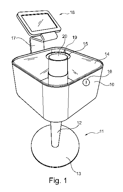
Fig. 1 is a three-dimensional view of a vending machine according to an
embodiment of the
present invention. The main body of the vending machine is formed by a
container 10 which is
box-shaped with rounded corners. The containers outer dimensions may in
particular be 50cm x
50cm with a height of 25cm. This size facilitates placement even in confined
spaces, it is user
friendly and provides sufficient capacity for many use cases. However, other
dimensions are
8
CA 02962357 2017-03-21
WO 2016/048159 PCT/N02015/050168
possible and consistent with the principles of the invention, but in order to
provide the vending
machine with a compact size which fits at a large number of places, the size
should be no larger
than 100cm x 100cm with a height of 50cm. The container 10 is carried by a
stand 11 attached to
the container 10. The container 10 may be formed of aluminum, white
polycarbonate or acrylate
polymer. The stand 11 in the embodiment illustrated in Fig. 1 comprises a pole
12 and a round
ground plate 13, but other configurations may be contemplated. The upper side
of the container
is covered with a removable lid 14 which form-fits into an upper opening of
the container 10.
The lid 14 is transparent and may be formed of polycarbonate or acrylic glass.
The lid 14 is curved
outwardly such that its height is in particular between 40 and 50mm, e.g.
44mm. An aperture 15
10 is formed centrally in the lid 14 and should be dimensioned large enough
for a user to reach inside
the container 10 by hand, in particular the diameter of the aperture 15 may be
16cm, but could
also be in the range of 15cm to 30cm depending on whether the vending machine
is provided
with a cooling function, and the size of the products (e.g. for newspapers or
books, the aperture
may be larger). The aperture is shown as a circular opening, but other shapes
may be
contemplated.
A lock 16 may be provided for locking and unlocking the lid 14 to/from the
container 10. The
illustrated lock 16 is of rather schematic nature and illustrated as a
mechanical lock, but the
invention may also be implemented with an electro-mechanical lock which is
operable by means
of a wireless key, by a processor, or a specific code entered via a user
interface. The processor and
the user interface will be described in further detail below. On a back side
of the container 10, a
display holder 17 may be attached, and the display holder 17 may hold a user
interface 18, for
example in the form of a tablet computer. If the display holder 17 is needed
depends on the kind
of user interface 18 used in a particular embodiment. Instead of or in
addition to the tablet
computer shown in the drawing, the user interface 18 could comprise a user
communication
device 63 for communicating with a cell phone or a tablet computer belonging
to the user, for
connecting to some other mobile device, or it may be a card reader or NFC
reader for reading a
smart or credit card of the user. If the user interface 18 is a user
communication device 63
without a display at the vending machine, the display holder 17 may not be
necessary. The user
communication device 63 may by a radio transmitter/receiver. Instead
information may be
displayed on the mobile device of the user.
In the embodiment illustrated in Fig. 1, the inside of the container 10
includes an aperture access
enabling device 19 or closing device in form of a piston 20 which closes the
aperture 15 when
telescopically extended out of the upper end of the pole 12 and which opens
the aperture 15
9
CA 02962357 2017-03-21
WO 2016/048159 PCT/N02015/050168
when telescopically retracted. Thus, the upper portion of the pole 12 may form
a cylinder which is
guiding the piston 20, namely the cylindrical outer side of the piston 20 is
guided by the cylindrical
inner side of the pole 12. Alternatively, there may be provided a separate
cylinder for guiding the
piston 20, which cylinder is attached to the container 10 or the pole 12. The
upper end of the
piston 20 reaches into or approximates the aperture 15 and is dimensioned
smaller than the
aperture 15, e.g. has a smaller diameter, but it should also be dimensioned
large enough to avoid
that products stored in the container can be removed in a closed state. If the
vending machine is
provided with a cooling function, then it might be desirable to avoid a gap in
between the
aperture 15 and the piston 20 or to keep it small.
Fig. 2 shows the vending machine according to an embodiment of the present
invention in a
three-dimensional view from a different perspective.
Fig. 3 shows a schematic cross-sectional view along a plane which is parallel
to a side wall of the
container 10 and between this side wall and the piston 20. The lid 14 is not
shown in Fig. 3. The
container 10 comprises four side walls 21 which are unitarily and
monolithically formed and
provided with rounded corners in a top view. A bottom cover 22 is provided.
The bottom cover 22
may have the same shape as the lid 14, and it may be made from the same
material as the lid 14.
In some embodiments the central aperture may have a different size which is
adapted to the pole
12 to pass through the bottom cover.
The bottom cover 22 may be removable in order to provide easy access to the
inside for
maintenance and repair purposes and lockable to the container 10 in a similar
manner as the lid
14. Alternatively, the bottom cover 22 may be attached to the lower inner edge
of the container
10 by adhesive. Also, the bottom cover 22 can be attached to the pole 12 or a
base plate 23. The
base plate 23 is either formed unitarily and monolithically with the side
walls 21 or attached
thereto with known means (e.g. adhesive, screws, snap-fit connections). The
base plate 23 can be
attached to a flange 25 of the pole 12 (e.g. adhesive, screws, snap-fit
connections). The base plate
23 is carrying weight sensors 24 which are attached thereto. The number of the
weight sensors 24
may be four wherein each of the sensors is positioned in a corner area of the
base plate 23. Also
other numbers of weight sensors are possible such as three, or more than four.
On the underside
of the base plate 23 there is provided a controller 26 managing the
communication and operation
of the vending machine. In order to be able to do so, the controller 26 may be
supplied with
electrical power from an external source by means of a conventional power
cable. Alternatively,
an internal power source, for example rechargeable batteries, may be provided.
The controller 26
CA 02962357 2017-03-21
WO 2016/048159 PCT/N02015/050168
may be connected to an actuator 27, a camera 28, the weight sensors 24 and the
user interface
18. The controller 26 may basically be a personal computer including a
processor and internal
memory which stores necessary software and/or firmware components as well as
data.
Alternatively, the controller may be an application specific integrated
circuit (ASIC), a field-
programmable gate array (FPGA) or some other device configured or adapted
specifically for the
purposes of the present invention, but a generic computer device may provide
more flexibility
with respect to hardware (e.g. CPU power, memory and other components) and
software changes
(e.g. Linux, Windows) and high compatibility regarding the connected devices
such as the camera
28. The controller 26 may provide the mentioned components (actuator, camera,
weight sensors)
with power by means of a cable and exchange data by means of a cable. The
controller 26 may
also communicate wirelessly with the components for exchanging data.
The actuator 27 is an actuator which can extend and retract telescopically,
wherein one end of
the actuator 27 is mounted to the pole 12 and the other end is mounted to the
piston 20. In other
words, a piston of the actuator 27 can telescopically extended from a cylinder
of the actuator 27
and retracted into the cylinder of the actuator 27, which in turn
telescopically moves the piston
20. The actuator 27 may be a low voltage actuator operable with for example 12
or 24V, which
can be provided via, or under control of, the controller 26. One example of
such an actuator 27 is
the actuator LA22 from LINAK . Regarding placement, the actuator 27 can be
positioned entirely
or partly inside the pole 12, which is holding the container 10. For operating
the actuator, the
controller 26 includes an actuator driving unit 29 which regulates e.g. the
current which the
actuator 27 is provided with. The driving unit 29 is operating the actuator 27
such that it shows
characteristics like a soft start and a soft stop. One example for such an
actuator driving unit 29
may be the TR-EM-208 from LINAK .
On top of the weight sensors 24 there is placed a product plate 32 which is
arranged such that it
can freely move up and down along the longitudinal direction of the pole 12.
Inside the container
10 and on the product plate 32, different products can be placed.This is
illustrated in the example
of Fig. 3 as a chocolate bar 30 and a beverage can 31. The product plate 32
and the weight
sensors 24 are optional. The invention also includes embodiments without
these, wherein in such
a case, the products 30, 31 can be placed on the base plate 23 directly.
The camera 28 can be used both as deterrent against theft and for recognition
of the products 30,
31 while the products 30, 31 are stored in the container 10 (the removed
product is then the one
which is not present anymore after the purchasing process) or during removal
from the container
11
CA 02962357 2017-03-21
WO 2016/048159 PCT/N02015/050168
10. Product recognition will be described in further detail below. The camera
28 may be mounted
inside the container 10 as illustrated in Fig. 3, in the upper end of the
piston 20 (in particular in
the upper surface of the piston 20), or in the curved part of the display
holder 17 (underneath the
tablet computer and directed towards the aperture). In Fig. 3, the camera 28
is positioned such
that its angle of view can capture all of the products within the container
10. At least one camera
28 is necessary for visual recognition of products, but there could also be
provided more than one
camera 28. Having more cameras 28 may make the recognition of products more
reliable and the
overall angle of view wider, but may make an image processing more complex and
slower. In the
illustrated embodiment of Fig. 3, the camera 28 is provided within the
container 10. However, as
already mentioned, it would also be possible to attach the camera outside the
container, namely
mount it to the display holder 17, e.g. underneath the user interface 18 shown
in Fig. 1, such that
the camera is primarily directed towards the aperture 15 in order to capture
images of the
products while they are removed from the container 10 through the aperture 15.
The camera 28
can also be integrated into the upper surface of the piston 20 and directed
upwards, which would
have the benefit that the products which are removed through the aperture 15
necessarily pass
by in between the aperture 15 and the retracted piston 20 and would thus also
pass by the
upwardly arranged camera. This in turn would have the advantage that the
camera is capturing
the removed product from underneath (and on an opposite side to the hand of
the user) making
it unlikely that the hand of the user is covering the product to an extent
which would negatively
influence the product recognition.
The inside of the container 10 below the lid 14 and above the plane which is
adapted to carry the
products 30, 31 (the product plate 32 or the base plate 23) is free of
dividing walls. Thus, a single
continuous space is provided for storing the products 30, 31. This provides
the benefit that the
products 30, 31 can have any shape or size as long as they fit into the
container 10 and through
the aperture 15. Also, the products do not have to have a stable outer shell
(e.g. a beverage can),
but could be soft or flexible (e.g. a scarf or a softball). Due to omitting
compartments or dividing
walls within the container 10, the products 30, 31 do not have to be sorted or
carefully stacked
within a specific compartment. Many prior art vending machines require sorting
of specific
products in assigned compartments and some even require to stick the products
into certain
positions of a spiral which dispenses the products upon request. With the
present invention, if for
example softballs or golfballs are sold, refilling the vending machine simply
requires removal of
the lid 14 and the softballs can be dumped into the container 10 until it is
full, which allows a very
easy handling.
12
CA 02962357 2017-03-21
WO 2016/048159 PCT/N02015/050168
Fig. 4 shows a three-dimensional view from above into the container 10. This
Figure shows the
already described base plate 23 with the weight sensors 24 mounted thereon in
all four corners
and the attachment of the base plate 23 to the flange 25 of the pole 12 by
means of screws. The
product plate 32 is not illustrated in Fig. 4.
Figs. 5a and 5b show the display holder 17 holding a tablet computer 33 as
user interface 18. Fig.
5a shows basically a front view of the straightened display holder 17. As
illustrated, the display
holder 17 comprises a band-shaped leg 34 at the upper end of which a casing 35
is attached or
monolithically formed with. The casing 35 is adapted to encase a tablet
computer 33. Fig. 5b is a
side view of the display holder 17 in a final shape. The leg 34 comprises
(when attached to the
container 10) in an area above the lid 14 a 900 curvature towards the aperture
15 and at a
position at the lower end of the casing 35 a 1450 curvature backwards.
Reference numeral 36
indicates a cover for closing the casing 35 on the back side which may be
lockable. The display
holder 17 is made of acrylate polymer or polycarbonate. The display holder 17
could also be made
of metal and bent into the shape as shown in Fig. 5b. Necessary cables 37 can
be guided inside
the display holder 17 through appropriate passages. The display holder 17 may
be attached to the
inside of the container 10, wherein for this purpose, the lid 14 may be
provided with an
appropriate recess. This way of attachment hides power cables and data cables
leading to the
controller and other components. Optionally, there may be provided a card
reader 49 at the user
interface 18, which is operatively connected to the user interface 18 (e.g.
plugged into a tablet
computer). The card reader 49 may be adapted to read payment cards (e.g.
credit cards) or smart
cards by way of magnetic stripes while the cards are swiped through the card
reader 49, it may be
adapted to read a chip of the cards while the cards are inserted into the card
reader 49, or the
card reader 49 may be an NFC reader. The card reader 49 may also be capable of
reading an ID
card of the user by scanning the ID card or by reading chip integrated into
the ID card. A smart
card may be a card provided by the vending machine manufacturer or the vending
machine
operator which is adapted to identify a user.
While the embodiments described above include a number of aspects consistent
with the
principles of the invention, many alternatives may be contemplated. For
example, while the
controller 26 is described as a computer controlling the sensors and the
actuator, while the user
interface 18 is described as a tablet computer which controls the display,
communication with the
user interface for user identification and payment handling, as well as
network communication,
which will be described in further detail below, it will be realized that
these two computers could
13
CA 02962357 2017-03-21
WO 2016/048159 PCT/N02015/050168
be combined into one, or they could be configured such that tasks were shared
between them in
a different manner than described above.
It will also be understood by those with skill in the art that the overall
shape of the device can be
different (for example circular, or even ball shaped like a globe). Also, the
aperture may have a
different position in the lid, and the closing mechanism can, for example, be
in the form of a door
that is hinged or a plate that is moved, or slides, parallel to the lid in
order to open and close the
aperture. In trusted environments it may even be contemplated that the
aperture access enabling
device 19 or closing device initiates an alarm that sounds if a user reaches
inside the machine
without first logging in or otherwise identifying themselves. The alarm may,
for example, be
operatively connected with one or more light sources (e.g. lasers) and
corresponding light
detectors configured such that the light from a light source will be prevented
from reaching its
corresponding light sensor if a hand is inserted into the machine. After
identification of a user, the
alarm may be disabled until a transaction has been completed.
The number of weight sensors required may also be reduced, even as low as to
only one, provided
that the product plate 32 can move freely and exert the same pressure onto the
weight sensor
irrespective of where in the machine a product is positioned.
Finally, it will also be understood that while compartments for separating
different types of
products have been described as unnecessary, the use of some sort of
compartmentalization or
subdivision of the space inside the machine is not inconsistent with the
principles of the
invention.
Fig. 6 shows schematically the communication ability of the vending machine
with a remote
server 38. For this purpose, the server 38 is connected to the internet and
accessible by a plurality
of vending machines via the internet. The vending machine establishes the
connection to the
internet (and thus to the server 38), by a network communication device 39
which may be
included in the controller 26 or which may be included in the user interface
18, e.g. the
communication interface of a tablet computer. The network communication device
39 and the
user communication device 63 (Fig. 3) could be separate devices or the same
device depending on
the chosen kind of wireless communication (e.g. Wi-Fi, Bluetooth). The network
communication
device 39 may establish wireless communication 41 to a mobile communications
network used by
mobile phones, or establish wireless communication 41 to a Wi-Fi router 40
which is connected to
the internet. The network communication device 39 could also establish such a
communication in
14
CA 02962357 2017-03-21
WO 2016/048159 PCT/N02015/050168
form or a wired communication. The communication with the remote server 38
allows central and
server controlled pricing such that the prices of certain products can be
changed centrally by
means of the server 38 instead of changing these data at each of the vending
machines. Further,
the server 38 can provide the vending machines centrally with product
information, e.g. product
information that is given to the user or product information that relate to
the purchasing process,
such as data saved in a sample storage, which will be described in further
detail below. The server
38 can further receive the inventory status of the vending machines such that
it can be centrally
determined when a vending machine needs to be refilled without spending time
checking each
vending machine regularly. Further, it enables central logging of sales,
including the number
already sold of each individual product.
Fig. 7 shows a block diagram of a control scheme of the vending machine
according to an
embodiment of the present invention. Box 26 schematically illustrates the
controller. The
controller 26 may be running an operating system such as Windows or Linux and
may be
supported by Java. A user 42 may identify himself via the user interface 18
which can be the
user's own mobile device, such as a mobile phone or a tablet computer (e.g.
based on Android,
Windows or i0S), or it can be a device attached or integral to the vending
machine, such as a
touch screen, a keyboard, a tablet computer or a combination of these. The
identification can also
be conducted by a combination of the above, for example via a cloud service
47, e.g. Twilio or Link
Mobility. In such a case the cloud service 47 is a SMS-service which might be
used for
authorization in the login process. For example, when the user logs in on the
touchscreen he
enters his phone number, and cloud service 47 will send a SMS to that number
with an
authorizing code, and the user enters that code for authorization. It is used
as a two-way
authorization process. In case of the user interface 18 being the users own
mobile device, there
may be provided application software 43 which can be installed on the mobile
device and which
manages the communication between the mobile device of the user 42 and the
vending machine.
It is also possible to recognize the user 42 by means of face recognition
using a camera of the user
interface 18 (e.g. the tablet computer 33). Yet another alternative is to use
a fingerprint reader
installed as part of the vending machine or on the user's own mobile device.
Thus, a user 42
identifies himself at the vending machine before a transaction process using
his own mobile
device (e.g. the user's personal phone's NFC), or in case of the user
interface 18 being provided at
the vending machine by entering a pin code, by inserting a smart card or his
credit card into the
card reader 49, or e.g. by face or fingerprint recognition. The user interface
18 may communicate
with the controller 26 and other components such as the camera 28, the weight
sensors 24
wireless (e.g. Wi-Fi or Bluetooth), i.e. communication between user interface
and sensors is
CA 02962357 2017-03-21
WO 2016/048159 PCT/N02015/050168
wireless. The controller 26 (or, optionally, the user interface device)
verifies the identification by
communicating with the remote server 38. After the approved identification,
the controller 26
opens the aperture access enabling device 19 by means of the driving unit 29
which retracts the
piston 20 into its opened position. The user 42 can then reach with his hand
through the aperture
15 into the container 10 and remove one or more of the products 30, 31.
According to some embodiments, the controller may include a sample storage 44
which stores
sample descriptions consisting of pictures with drawn outlines of the products
30, 31 to be sold.
The sample image files stored in the sample storage 44 provide outlines and
imprint images from
different angles of the product. The sample files could be created for example
by providing an
imaginary sphere around the product which sphere is divided by a grid such as
the longitude and
latitude of the earth which grid lines are provided for example in intervals
of 10 (or any other
interval). Then from the angle of every intersection point of these grid lines
an image is taken and
from this image, an outline of the product and the imprint is saved. Thus, the
sample storage 44 is
also a database providing a comparison basis for a product recognition
executed by a recognition
module 45. The recognition module 45 executes recognition software 46 such as
SendSight SDK.
The modules mentioned here, can be hardware or hardware-software combinations.
In order to
recognize the products in the container 10 or in the vicinity of the aperture
15, the recognition
module 45, in particular camera based object recognition module 60, receive
image information
from the camera 28 which can be a fixedly installed camera or which can be a
controllable camera
which can be moved (e.g. moved up, down, left and right) as directed by
control signals from the
controller 26, in order to enlarge the angle of view of the camera. The object
recognition module
60 is adapted to recognize each of the products stored in the container 10 by
comparing the
image data from the sample storage 44 by means of the recognition software 46.
In particular, the
object recognition module 60 recognizes the products by comparing the outline
(the shape) of the
products with the stored samples and by comparing the imprint on the products
with the stored
samples. This way, the object recognition module 60 is capable of recognizing
all the products 30,
31 present in the container 10 and determine which of the products has been
removed when the
purchasing process is finished, because this/these product(s) is/are not
present inside the
container 10 anymore. Or, in case the camera 28 is arranged in the vicinity of
the aperture 15, the
object recognition module 60 recognizes which of the products 30, 31 is
removed out through the
aperture 15. In addition to, or alternative to the image recognition described
above, the
recognition module 45 can identify which of the products 30, 31 is removed out
of the container
10 during a purchasing process by determining the weight difference before and
after the
purchasing process by means of weight recognition module 61. For this purpose,
the sample
16
CA 02962357 2017-03-21
WO 2016/048159 PCT/N02015/050168
storage saves the weights of all products 30, 31 stored in the container 10.
This weight
recognition can be executed in addition to the image recognition in order to
improve accuracy or
it can be executed alternatively to the image recognition. Furthermore, in
addition to at least one
of the image recognition and the weight recognition, or alternatively thereto,
the recognition
module 45 can recognize the products 30, 31 removed from the container 10
based on RFID-
technology by means of RFID recognition module 62. RFID is the abbreviation
for radio-frequency
identification, wherein identification tags are attached to the products 30,
31, which identification
tags transfer data to a receiving module by means of electromagnetic fields.
For this purpose, the
sample storage saves the RFID data of all products 30, 31 stored in the
container 10. The data
received from the RFID tags can be compared to the sample data stored in the
sample storage 44
in order to recognize the products 30, 31 as they are removed out through the
aperture 15. An
RFID reader would have to be placed near the aperture 15.
After the purchasing process, the user 42 indicates through the user interface
18 the end of the
purchasing process and the controller 26 closes the aperture access enabling
device 19. In order
to give the user 42 appropriate feedback after the purchasing process is
finished, the controller 26
initiates the sending of a text message via a cloud service 47, e.g. Twilio,
to a mobile phone 48
associated with the user 42.
This mobile phone 48 may be the one which is used as user interface 18.
Payment can be
conducted by a payment method which is registered in the account of the user,
by mobile
payment (by means of the mobile phone) or by a credit card which is read by
the card reader 49
(this can be the credit card which is also used to initially identify the
user).
According to one aspect of the invention, the user 42 can indicate interests
or preferences such
that the user 42 receives additional messages, e.g. coupons which are
personalized to his
interests or preferences from the vending machine in addition to receiving the
products 30, 31. As
the products 30, 31 which the user 42 is buying or has bought before also
indicate the interests of
the user 42, it is possible to personalize the messages or coupons for the
user 42 based on the
current purchase and/or the purchase history of the user 42. The coupons can
be personalized to
age, gender, shopping interests, purchase history, vending machine location,
home address, work
address, etc., as well as any commercial campaign requested by an advertiser.
17
CA 02962357 2017-03-21
WO 2016/048159 PCT/N02015/050168
Fig. 8 shows another embodiment of the vending machine according to the
present invention. In
order to avoid repetitions, the above description shall apply also to this
embodiment, and only
aspects will be explained in which this embodiment is differs from the above
explanation.
The lid of this embodiment corresponds to the lid 14, but without the aperture
15. The inside of
the container 50 of this embodiment comprises a dividing wall 51 such that a
delivery
compartment 52 is formed which is separated by the dividing wall 51 from the
rest of the inside of
the container 50, which forms a product compartment 53. In a top view, the
dividing wall 51 is
fully separating the delivery compartment 52 from the product compartment 53,
but the upper
side of the delivery compartment 52 is opened as shown in Fig. 8. The dividing
wall 51 is fixedly
attached to the base plate 23 or monolithically formed with it. The products
30, 31 in the product
space 53 can be moved by the user 42 by means of a manipulator arm 54 from the
product space
53 to the delivery compartment 52. Alternatively, to the manipulator arm,
there could be
provided another manipulator device such as a manipulator crane. From the
delivery
compartment 52, the user can take the product out through a dispensing opening
57. As every
product which is sold has to pass the way into the delivery compartment 52, it
is sufficient to
conduct the recognition of the product in or on the way into the delivery
compartment 52.
Therefore, the camera 28 is arranged such as to be directed towards the upper
opened side of the
delivery compartment 52. Also the product plate 55 only has to be provided in
the delivery
compartment 52 and corresponds apart from this to the product plate 32. Weight
sensors 56
corresponding to the weight sensors 24 may be arranged underneath the product
plate 55. As the
aperture access enabling device 19 is not necessary in this embodiment, the
upper end of a pole
58 can be attached to the underside of the base plate 23 by means of a flange
59.
While the manipulator arm 54 is shown as extending through the side wall of
the machine, it
could equally well be extending through the top lid. Furthermore, it could be
contemplated to
provide some form of a conveyor belt between the delivery compartment 52 and
the product
compartment 53. A user would then use the manipulator arm 54 to place a
product on the
conveyor, which would transport the product to the delivery compartment. While
such a
configuration would increase the number of movable parts, it would also give
an unobstructed
view of a selected product as seen from a camera 28 mounted above the
conveyor.
Fig. 9 shows another embodiment, in which the embodiment of Fig. 8 is
modified. In order to
avoid repetitions, only aspects are described in which this embodiment
distinguishes from the
one shown in Fig. 8.
18
CA 02962357 2017-03-21
WO 2016/048159 PCT/N02015/050168
A container 65 of this embodiment comprises dividing walls 66 which are
dividing the inside of the
container 65 into multiple product compartments 67 and a delivery compartment
68. The delivery
compartment 68 is extending through an opening 70 which is provided in the
side wall of the
container 65. The part of the delivery compartment 68 within the container 65
is provided with a
conveyer belt 69 and the part of the delivery compartment 68 outside the
container 65 is formed
as a collecting basket 71. The vending machine according to this embodiment
may comprise a
manipulator crane 72 which reaches through a curved gap 73 formed in a lid 74
through the lid
74. The lid 74 corresponds to the lid 14 with the exception that instead of
the aperture 15, the
curved gap 73 is provided. The manipulator crane 72 can be operated manually
by the user in
order to pick the desired product 30, 31 and to move the product from the
product compartment
67 onto the conveyer belt 69. The conveyer belt 69 then moves the product from
e.g. from a
central position of the container to the opening 70 where the product is
pushed by the conveyer
belt! or rolls through the opening 70 into the collecting basket 71 where the
user can take the
product. As every product which is sold has to pass the way into the delivery
compartment 68 or
onto the conveyer belt 69, it is sufficient to conduct the recognition of the
product in or on the
way into the delivery compartment 68 as in the embodiment of Fig. 8.
Fig. 10 shows another embodiment of the vending machine according to the
invention. Compared
to the embodiment shown in Fig. 1, the vending machine of this embodiment does
not include
the display holder 17 and the piston 20. The user interface of this embodiment
is formed by the
user communication device 63 which communicates with a mobile device of the
user. The
aperture access enabling device 19 in this embodiment is formed by a light
barrier device 75
which comprises a light transmitter on a side wall and a light sensor on an
opposite side wall, or
which comprises a light transmitter-sensor on a side wall and a mirror on the
opposite sidewall.
The light barrier device 75 is capable of emitting several light beams (e.g.
also including laser
beams) along an array such that a plurality of parallel light beams 76 is
emitted towards the
opposite side wall where the sensor or the mirror of the light barrier device
75 is located. The
light beams 76 may be colorful for an attractive appearance, and in order to
be visible they may
partly be directed towards a medium that will subject the light to diffuse
reflection, e.g. plastic
parts of the vending machine, or even an artificial mist (steam, a spray of
droplets or something
similar). The light beams 76 may also look like prison/sprinkler bars,
visually blocking the hole.
When access into the container 10 is enabled, the light barrier device 75 is
turned-off. The light
beams 76 thus are extending in parallel and horizontally underneath the
aperture 15. When
access into the container 10 is prohibited, the light barrier device 75 is
turned on. In the turned on
19
CA 02962357 2017-03-21
WO 2016/048159 PCT/N02015/050168
state, the light barrier device 75 can recognize the interruption of one or
more of the light beams
76 and the vending machine can thus recognize an unauthorized access into the
container 10. The
aperture 15 is not physically blocked, but if the user, or any other person,
puts his hand in through
the aperture 15 without logging in, an alarm would go off and a picture would
be taken of the
user or person (in embodiments where the camera is directed towards the user).
Thus, a user has
to log in or otherwise be identified before being able to reach with his arm
into the container 10.
The user can log in with his mobile device, e.g. mobile phone, communicating
with the vending
machine with either NEC or other communication. After logging in, the aperture
15 would no
longer be visually blocked with the light beams 76 and the user can reach
through the aperture 15
into the container 10 of the vending machine and pick a product. The product
is recognized by
one or more of the recognition modules described before, e.g. with RFID and/or
camera and/or a
weight sensor. The purchase of the product will then be registered on the
customer's account.
This embodiment would have the benefit that without the screen and the
actuator the cost would
be reduced, and it could be good for places giving out coffee capsules or as
an inventory control.
While this embodiment has been described as having no display or screen, it is
consistent with the
principles of the invention to include a display or screen, e.g. a tablet
computer, in embodiments
without the actuator or other physical blocking means.
Reference is now made to Fig. 11, which illustrates an exemplary method that
can be performed
by a vending machine operating in accordance with the principles of the
invention.
The method starts in an initialization step 1101. This step may be selected
from many methods
that are well known in the art, such as a user pushing an activation button, a
proximity detector
(e.g. a camera) detecting the presence of a user, etc. The step may also be
merged with the
following step 1102, in which user input identifying the user 42 is received
from the user interface
18. In other words, the vending machine may first be initialized and present a
prompt for user
identification in an initialization step, or a user input of identification
may serve as the
initialization step.
The user interface 18 may be any combination of the devices and capabilities
that have already
been described, and for the purposes of the description of the purchase or
transaction process,
the user interface 18 will be considered as including any communication
interface involved in the
process of exchanging information with a user or an external device operated
by the user. As
such, the user interface 18 may be any combination of the tablet computer 33
or other display
CA 02962357 2017-03-21
WO 2016/048159 PCT/N02015/050168
device integral to the vending machine, the card reader 49 (e.g. magnetic
strip reader or
smartcard reader), the camera 28, the user communication device 63 (e.g. a
Bluetooth, Wi-Fi, NEC
or other wireless interface capable of communicating directly with a device
operated by the user),
or network communication device 39 (e.g. wireless or wired communication with
an external
network, for example a cellular mobile network and intermediary devices
including servers which
in turn forward information to or from a device used by the user).
This means that the input received in step 1102 may be received as user input
from a keypad or
keyboard or touchscreen, from the card reader 49 reading user identity from a
credit card or
smartcard, it may be based on face recognition from camera input or
fingerprint recognition from
a fingerprint reader, user credentials received directly from a user device
over the user
communication device 63 or indirectly via the network communication device 39,
for example as
a text (SMS) message received from a cellular mobile network. Also, as
described above,
networked services such as Twilio or Link Mobility may be involved.
As soon as the user 42 is identified by the controller 26 based on the
information received in step
1102, the aperture access enabling device 19 may enable access to the items in
the vending
machine in step 1103. The aperture access enabling device may be any of the
devices described
above configured to enable or prevent access to the products or items stored
inside the vending
machine, either physically by blocking the aperture 15, or logically
preventing access by issuing an
alarm if an attempt is made at accessing items without prior user
identification.
After the aperture access enabling device 19 has enabled access, the
controller 26 monitors input
from the sensors that are configured to detect items that are removed from the
container 10, 50,
65. As described above in connection with the recognition module 45, several
types of sensors
can be used either alone or in combination. Examples of sensors include one or
more weight
sensors 24, 56 that detect the weight of the item that has been removed, one
or more cameras 28
that capture one or more images of the item that is being removed and subject
the one or more
images to an image recognition or feature extraction that is capable of
detecting characteristic
visual features of the item, and an RFID reader that can read an RFID tag
attached to the item.
When the controller 26 receives input from the sensors, the input can be
analyzed and the type of
item can be recognized in step 1105. This analysis and recognition can be
based on a comparison
of the received and analyzed sensor input with a catalog of characteristic
features associated with
respective items or products. This catalog can be stored in a database or some
other data format
21
CA 02962357 2017-03-21
WO 2016/048159 PCT/N02015/050168
in local memory in the vending machine. Alternatively, the information can be
available from a
remote server.
When the recognition has been made in step 1105, the controller may request a
confirmation of
acceptance from the user in step 1106. This request may be presented on a
display of the vending
machine (e.g. user interface mounted to the vending machine), or as a message
transmitted
directly or indirectly (e.g. over a mobile network or the Internet) to a
device operated by the user
to be displayed there. Included in the request for confirmation may be a
price, or any other
conditions the user must accept in order to keep the item. Such conditions
may, for example, be
to be included on a mailing list, or to be registered in a database of users
maintained by a remote
server.
Various embodiments of the invention may receive confirmation from the user in
different ways.
According to some embodiments, the user confirms using a graphical user
interface, such as the
tablet computer described above. Alternatively, or in addition, the user may
have to enter
payment information by swiping a credit card or causing a smart card or a card
or other device
with an embedded NEC tag to be read by a corresponding reader attached to the
vending
machine, as described above. Some or part of the confirmation information may
also be received
from a mobile device operated by the user, for example over Bluetooth, Wi-Fi
or as SMS, or over
the Internet, for example by operating a web browser installed on the mobile
device.
The information received as confirmation may include credit card information
from a card reader,
mobile payment information from a mobile device associated with the identified
user,
information identifying a debit account associated with the identified user,
and information
confirming the identified user's acceptance to receive one or more messages
from a set of
messages stored remotely.
If confirmation is not received, for example within a predetermined time or a
message of
rejection is received instead, as determined in step 1107, the method proceeds
to step 1108
where a cancellation is initiated. Cancellation may involve prompting the user
to return the item
to the container, registering that the item is indeed returned to the
container (in a which is the
reverse of the detection of removal of an item), and cancellation of all
pending transaction steps.
Otherwise, i.e. if confirmation is received (or if the item is not returned
within a predetermined
time limit), the transaction is finalized in step 1109. Finalization of the
transaction may include
transfer of funds by a payment service, registration of the user in a user
database, or the
22
CA 02962357 2017-03-21
WO 2016/048159 PCT/N02015/050168
implementation of any other conditions accepted by the user. Finalization may
also include
registration of data related to the transaction for bookkeeping and statistics
purposes. The
finalization may also include issuance of a receipt, a coupon or any other
message related to the
transaction. Such a message may be received immediately or delayed, and only
once or
repeatedly. For example, a remote server may include a set of available
messages, and the
message or messages sent to the user may be chosen from a subset of this set
of messages,
where the subset are messages that are selectable based on criteria associated
with the removed
item (i.e. with the one or more characteristics used to identify the item, or
the identified item
itself).
In particularly trusted environments, for example at a workplace, access to
items may be
permanently enabled or enabled without prior identification of the user. The
identification step
1102 may then be combined with confirmation receipt in step 1107.
In addition to the features described above, the vending machine of all
embodiments may be
provided with the following features:
Cooling function: Optionally, the vending machine may be provided with a
cooling function in
order to cool the inside of the container.
Data analysis: As the vending machine makes it possible to acquire all kinds
of data such as
regarding the vending machine environment, the user and the product, it allows
combining these
data in order to achieve more sophisticated statistics and analysis. These
results could be used for
marketing purposes.
User data acquisition: In case of registered users, data regarding every user
can be acquired. This
allows individual user statistics, and also the user themselves provide user
information during the
web registration.
Social network integration: Do to the vending machines being connected to the
remote server 38
and thus being connected to the world wide web, the vending machine allows a
social network
integration which means that user can share or forward offers, gifts or
coupons to other users via
social networks.
Eye tracker: The image processing can additionally comprise the feature to
recognize and track
the eyes of users and/or people looking at the vending machine. This allows
determining where
23
CA 02962357 2017-03-21
WO 2016/048159 PCT/N02015/050168
the user/people look at, in particular at which products they look at or at
which advertising area
on the vending machine they look at. Having this kind of information allows
analyzing the
attractiveness of packaging, advertisement, products, design etc. Thus, it
would give feedback for
marketing purposes which could be used for improving marketing.
Additional network cameras: In addition to the cameras described above, one or
more additional
cameras can be attached to the vending machine These cameras may be configured
to capture a
view of people passing through the area surrounding the vending machine. The
cameras may be
in communication with the vending machine and/or the remote server 38. Image
processing
capabilities located either in the camera itself, in the vending machine or in
the server may be
used to detect and count the number of people passing by the machine.
Furthermore, face
detection may be used to detect the number of people who actually look at the
vending machine.
This information may be used to analyze the attractiveness of the vending
machine in various
locations by analysis of whether the vending machine catches the attention of
people passing by.
In particular it may be possible to determine the fraction of passersby that
look at the vending
machine, and the fraction that actually choose to interact with the machine
and complete a
transaction. The network cameras could also be useful in protecting the
vending machine from
damage or theft.
Coupons: A further example on how coupons could be assigned to a user could be
realized as
described in the following: When the user logs in at the vending machine by
means of his mobile
phone using his phone number, the mobile phone number may be shared if the log
in is
conducted by means of NFC (with NFC the user's phone may share the phone
number when
swiping the phone). This way the vending machine saves the phone number after
log in. When
the user chooses his preferred value coupon there will be a short text
explaining that the coupon
is sent to an application software after the purchase. When the user logs out
after the purchase
he receives a text message with an internet link. The user can click the link
and may be directed to
a website. On the webpage the user may be asked to enter personal details,
such as first name,
last name, mail, etc. Thereafter, the user receives a link to download an
application, and when the
application is downloaded it automatically adds the above information to the
personal profile of
the user. Then the user receives the value coupon in the application and it
can be used instantly.
Further, the disclosure of this invention includes the following aspects, and
the applicant reserves
the right to claim one or more of the aspects as follows:
24
CA 02962357 2017-03-21
WO 2016/048159 PCT/N02015/050168
A. Vending machine for selling products to a user, comprising:
a container for storing and displaying the products, the container having a
transparent
portion making the products visible from outside the container, and an
aperture for removing one
or more products by hand, wherein the aperture gives direct access to the
products;
aperture access enabling device for selectively opening and closing the
aperture;
recognition module for recognizing each of the products in the container.
B. Vending machine for selling products to a user, comprising:
a container for storing and displaying the products, the container having a
transparent
portion making the products visible from outside the container, and an
aperture for removing one
or more products by hand, wherein the aperture gives direct access to the
products;
aperture access enabling device for selectively opening and closing the
aperture;
recognition module for recognizing each of the products in the container, the
recognition
module comprising at least one from the group consisting of: camera based
object recognition
module, weight recognition module, a RFID recognition module.
C. Vending machine for selling products to a user, comprising:
a container having a product compartment for storing and displaying the
products, the
container having a transparent portion making the products visible from
outside the container;
the container further comprising a delivery compartment which is accessible
from outside
the container via a dispensing opening;
a manipulator device which is operable by the user and by means of which the
products
can be transferred from the product compartment into the delivery compartment;
recognition module for recognizing each of the products.
D. Vending machine according to aspect C, wherein there is a diving wall
provided in
between the delivery compartment and the product compartment.
E. Vending machine according to aspect A or B, wherein a lid is loosely
covering the
container and removable when a lock is opened, which is selectively locking
the lid to the
container.
F. Vending machine according to any one of the aspects A, B or E, further
comprising an
actuator driving unit which is supplying an actuator for operating the
aperture access enabling
device with power and which is operating the actuation of the actuator.
CA 02962357 2017-03-21
WO 2016/048159 PCT/N02015/050168
G. Vending machine according to any one of the aspects A,13, E or F,
further comprising a
card reader for reading a payment card (e.g. credit card), a smart card or an
ID card of the user.
H. Method for operating a vending machine for selling products to a user,
the vending
machine comprising a container having a product compartment for storing and
displaying the
products, the container having a transparent portion making the products
visible from outside the
container; the container further comprising a delivery compartment which is
accessible from
outside the container via a dispensing opening;
recognition module for recognizing each of the products while transferred from
the
product compartment into the delivery compartment, or while the product is
located in the
delivery compartment.
The above mentioned aspects can be combined with one or more of the claims.
Further, it is
explicitly intended that the teaching of this invention covers any combination
of the above
described embodiments.
While the invention has been illustrated and described in detail in the
drawings and foregoing
description, such illustration and description are to be considered
illustrative or exemplary and
not restrictive and it is not intended to limit the invention to the disclosed
embodiments. The
mere fact that certain measures are recited in mutually different dependent
claims does not
indicate that a combination of these measures cannot be used advantageously.
26
CA 02962357 2017-03-21
WO 2016/048159
PCT/N02015/050168
List of reference signs
container
11 stand
5 12 pole
13 ground plate
14 lid
aperture
16 lock
10 17 display holder
18 user interface
19 aperture access enabling device
piston
21 side walls
15 22 bottom cover
23 base plate
24 weight sensors
flange
26 controller
20 27 actuator
28 camera
29 driving unit
chocolate bar
31 beverage can
25 32 product plate
33 tablet computer
34 leg of display holder
casing
36 cover
30 37 cables
38 remote server
39 network communication device
Wi-Fi Router
41 wireless communication
35 42 user
27
CA 02962357 2017-03-21
WO 2016/048159
PCT/N02015/050168
43 application software
44 sample storage
45 recognition module
46 recognition software
47 cloud service
48 mobile phone
49 card reader
50 container
51 dividing wall
52 delivery compartment
53 product compartment
54 manipulator arm
55 product plate
56 weight sensor
57 dispensing opening
58 pole
59 flange
60 camera based object recognition module
61 weight recognition module
62 RFID recognition mean
63 user communication device
65 container
66 dividing wall
67 product compartment
68 delivery compartment
69 conveyer belt
70 opening
71 collecting basket
72 manipulator crane
73 gap
74 lid
75 light barrier device
76 light beam
28