Sélection de la langue

Search

Sommaire du brevet 2965036 

Énoncé de désistement de responsabilité concernant l'information provenant de tiers

Une partie des informations de ce site Web a été fournie par des sources externes. Le gouvernement du Canada n'assume aucune responsabilité concernant la précision, l'actualité ou la fiabilité des informations fournies par les sources externes. Les utilisateurs qui désirent employer cette information devraient consulter directement la source des informations. Le contenu fourni par les sources externes n'est pas assujetti aux exigences sur les langues officielles, la protection des renseignements personnels et l'accessibilité.

Disponibilité de l'Abrégé et des Revendications

L'apparition de différences dans le texte et l'image des Revendications et de l'Abrégé dépend du moment auquel le document est publié. Les textes des Revendications et de l'Abrégé sont affichés :

  • lorsque la demande peut être examinée par le public;
  • lorsque le brevet est émis (délivrance).
(12) Brevet: (11) CA 2965036
(54) Titre français: TREUIL DE MARCHANDISE INSTALLE SUR PIVOT
(54) Titre anglais: SWIVEL MOUNT CARGO WINCH
Statut: Accordé et délivré
Données bibliographiques
Abrégés

Abrégé français

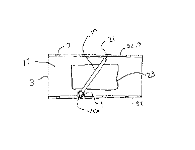
Linvention concerne un appareil de treuil destiné à être monté sur un lit de chargement comprenant un support de montage conçu pour être monté sur un bord latéral du lit de chargement, et un support de pivot monté de manière pivotante sur le support de montage autour dun axe de pivotement de treuil sensiblement vertical. Un treuil est fixé au support de pivot et configuré de telle sorte que, lorsque le support de montage est monté sur le bord latéral du lit de charge, un arbre de treuil du treuil est orienté sensiblement horizontalement et un fond du treuil est à un emplacement vertical qui est au-dessus dune surface supérieure du lit de charge de telle sorte que le treuil peut pivoter sur la surface supérieure du lit de charge. Le treuil peut être configuré pour être facilement entraîné par une clé à cliquet classique et communément disponible dune taille appropriée au treuil particulier.


Abrégé anglais


A winch apparatus for mounting to a load bed comprises a mounting bracket
adapted to
be mounted to a side edge of the load bed, and a pivot bracket pivotally
mounted to the
mounting bracket about a substantially vertical winch swivel axis. A winch is
attached to
the pivot bracket and configured such that, when the mounting bracket is
mounted to the
side edge of the load bed, a winch shaft of the winch is oriented
substantially horizontally
and a bottom of the winch is at a vertical location that is above a top
surface of the load
bed such that the winch can pivot over the top surface of the load bed. The
winch can be
configured to be conveniently driven by a conventional and commonly available
ratchet
wrench of a size appropriate to the particular winch.

Revendications

Note : Les revendications sont présentées dans la langue officielle dans laquelle elles ont été soumises.


CLAIMS
What is claimed is:
1. A winch apparatus for mounting to a load bed, the apparatus comprising:
a mounting bracket adapted to be mounted to a side edge of the load bed;
a pivot bracket pivotally mounted to the mounting bracket about a
substantially
vertical winch swivel axis; and
a winch attached to the pivot bracket and configured such that, when the
mounting bracket is mounted to the side edge of the load bed, a winch shaft of
the
winch is oriented substantially horizontally and a bottom of the winch is at a
vertical location that is above a top surface of the load bed such that the
winch is
pivotable over the top surface of the load bed.
2. The apparatus of claim 1 wherein the load bed includes a plurality of
stake
pockets spaced along side edges thereof, and wherein the mounting bracket is
configured to extend downward into one of the stake pockets.
3. The apparatus of any one of claims 1 and 2 comprising a cargo strap
attached to
the winch at an inner end thereof and comprising an engagement member on an
outer end thereof, and wherein when the winch is mounted on a first side edge
of
the load bed and the engagement member is attached to an opposite second side
of
the load bed, the winch extends over the top surface of the load bed
4. The apparatus of any one of claims 1- 3 wherein the winch is attached to
the
pivot bracket by bolts extending through corresponding bolt holes in the winch
and the pivot bracket.
8

5. The apparatus of any one of claims 1 ¨ 3 wherein the pivot bracket
comprises
right and left arms and wherein the winch shaft extends through shaft holes in
the
right and left arms and is rotatable in the shaft holes.
6. The apparatus of claim 5 comprising a bolt extending through the pivot
bracket
into the mounting bracket, and wherein the bolt provides the winch swivel
axis.
7. The apparatus of any one of claims 1 ¨ 6 wherein a drive end of the
winch shaft
defines a substantially square drive recess configured to receive a drive head
of a
ratchet wrench.
8. A load bed and winch apparatus, the apparatus comprising:
a load bed with a plurality of stake pockets spaced along side edges thereof;
a mounting bracket extending downward into one of the stake pockets and
attached to the stake pocket;
a pivot bracket pivotally mounted to a top end of the mounting bracket about a
substantially vertical winch swivel axis; and
a winch attached to the pivot bracket and configured such that a winch shaft
of the
winch is oriented substantially horizontally and a bottom of the winch is at a
vertical location that is above a top surface of the load bed such that the
winch is
pivotable over the top surface of the load bed.
9. The apparatus of claim 8 comprising a cargo strap attached to the winch
at an
inner end thereof and comprising an engagement member on an outer end thereof,
and wherein the winch is mounted on a first side edge of the load bed and when
the engagement member is attached to an opposite second side of the load bed,
the winch extends over the top surface of the load bed.
9

10. The apparatus of any one of claims 8 ¨ 9 wherein the winch is attached
to the
pivot bracket by bolts extending through corresponding bolt holes in the winch
and the pivot bracket.
11. The apparatus of any one of claims 8 ¨ 9 wherein the pivot bracket
comprises
right and left arms and wherein the winch shaft extends through shaft holes in
the
right and left arms and is rotatable in the shaft holes.
12. The apparatus of claim 11 comprising a bolt extending through the pivot
bracket
into the mounting bracket, and wherein the bolt provides the winch swivel
axis.
13. The apparatus of any one of claims 8 - 12 wherein a drive end of the
winch shaft
defines a substantially square drive recess configured to receive a drive head
of a
ratchet wrench.
14. A method of driving a winch to tighten a cargo strap on a load bed, the
method
comprising:
mounting the winch to a first side edge of the load bed;
winding a cargo strap onto a winch shaft of the winch, the cargo strap
comprising
an engagement member on an outer end thereof;
attaching the engagement member to a desired location;
forming a substantially square drive recess in a drive end of the winch shaft,
the
drive recess configured to receive a drive head of a ratchet wrench; and
inserting the drive head of the ratchet wrench into the drive recess and
operating
the ratchet wrench to tighten the cargo strap.

15. The method of claim 14 comprising pivotally mounting the winch to the
first side
edge of the load bed about a substantially vertical winch swivel axis such
that the
winch shaft is above a top surface of the load bed.
16. The method of claim 15 comprising attaching a mounting bracket to the
first side
edge of the load bed, pivotally mounting a pivot bracket to the mounting
bracket
about the winch swivel axis, and attaching the winch to the pivot bracket.
17. The method of claim 16 comprising attaching the winch to the pivot
bracket by
inserting bolts through corresponding bolt holes in the winch and the pivot
bracket.
18. The method of any one of claims 14 ¨ 17 comprising attaching the
engagement
member to one of a second side edge of the load bed opposite the first side
edge
and an object loaded on the load bed.
11

Description

Note : Les descriptions sont présentées dans la langue officielle dans laquelle elles ont été soumises.


CA 2965036 2017-04-24
SWIVEL MOUNT CARGO WINCH
This disclosure relates to the field of transportation equipment and in
particular a swivel
mount for a cargo winch such as is used with cargo straps to secure loads on
trailer beds.
BACKGROUND
Cargo is commonly secured to load beds on trucks and trailers by cargo straps.
Typically
stake pockets and rails are attached along each side edge of the load bed and
winches are
attached along one side of the load bed and the straps are thrown over the
load and hooks
on the outer ends of the straps are secured to the stake pockets or rails.
As a typical example United States Patent Number 8,096,740 to Parker et al.
discloses
winches mounted under the rails along one side of a trailer load bed with
cargo straps
extending upward over the rails on the winch side of the load bed and across
to the
opposite side of the load bed perpendicular to the longitudinal axis and the
edges of the
load bed.
United States Patent Number 6,626,621 to Hugg discloses winches removably
attachable
to the rails or pockets along one side of the load bed such that the winches
are somewhat
above the rails and the load bed. Again the cargo straps extend across to the
opposite
side of the load bed perpendicular to the edges of the load bed.
United States Patent Number 5,664,918 to Heider et al. discusses the problems
of
securing odd shaped loads since the straps cannot be turned to any significant
angle with
respect to the surface of the load bed, but must extend across the load bed
generally
perpendicular to the side edges thereof. It is typical therefore to use chains
and load
binders to secure odd shaped loads such as vehicles, which have their own
problems.
1

CA 2965036 2017-04-24
Heider then goes on to provide a winch mounted to the sides of the load bed
about a
horizontal pivot axis extending perpendicular from the side of the load bed.
The cargo
strap can then extend upward from the winch roller and be attached at an
elevated
location on a vehicle or like piece of equipment that is forward or rearward
of the winch.
SUMMARY OF TILE INVENTION
The present disclosure provides a winch apparatus that overcomes problems in
the prior
art.
In a first embodiment the present disclosure provides a winch apparatus for
mounting to a
load bed. The apparatus comprises a mounting bracket adapted to be mounted to
a side
edge of the load bed, and a pivot bracket pivotally mounted to the mounting
bracket
about a substantially vertical winch swivel axis. A winch is attached to the
pivot bracket
and configured such that, when the mounting bracket is mounted to the side
edge of the
load bed, a winch shaft of the winch is oriented substantially horizontally
and a bottom of
the winch is at a vertical location that is above a top surface of the load
bed such that the
winch can pivot over the top surface of the load bed.
In a second embodiment the present disclosure provides a load bed and winch
apparatus.
The apparatus comprises a load bed with a plurality of stake pockets spaced
along side
edges thereof. A mounting bracket extends downward into one of the stake
pockets and
is attached to the stake pocket, and a pivot bracket is pivotally mounted to a
top end of
the mounting bracket about a substantially vertical winch swivel axis. A winch
is
attached to the pivot bracket and configured such that a winch shall of the
winch is
oriented substantially horizontally and a bottom of the winch is at a vertical
location that
is above a top surface of the load bed such that the winch can pivot over the
top surface
of the load bed.
2

CA 2965036 2017-04-24
In a third embodiment the present disclosure provides a method of driving a
winch to
tighten a cargo strap on a load bed. The method comprises mounting the winch
to a first
side edge of the load bed; winding a cargo strap onto a winch shaft of the
winch, the
cargo strap comprising an engagement member on an outer end thereof; attaching
the
engagement member to a desired location; forming a substantially square drive
recess in
a drive end of the winch shaft, the drive recess configured to receive a drive
head of a
ratchet wrench; and inserting the drive head of the ratchet wrench into the
drive recess
and operating the ratchet wrench to tighten the cargo strap.
The present disclosure thus provides a winch apparatus and method that allows
cargo
straps to extend at various angles with respect to a winch attached to a side
edge of the
load bed to secure loaded objects of various sizes and dimensions. The winch
can be
configured to be conveniently driven by a conventional and commonly available
ratchet
.. wrench of a size appropriate to the particular winch.
DESCRIPTION OF THE DRAWINGS
While the invention is claimed in the concluding portions hereof, preferred
embodiments
are provided in the accompanying detailed description which may be best
understood in
conjunction with the accompanying diagrams where like parts in each of the
several
diagrams are labeled with like numbers, and where:
Fig. 1 is a schematic top view of an embodiment of the winch apparatus of the
present
disclosure securing a load on a load bed;
Fig. 2 is a schematic end view of the winch apparatus shown in Fig. 1;
3

CA 2965036 2017-04-24
Fig. 3 is a schematic side view of the embodiment of the winch apparatus of
Fig. 1;
Fig. 4 is a schematic top view of the embodiment of the winch apparatus of
Fig. 1;
Fig. 5 is a schematic end view of the square drive recess in the end of the
winch shaft
of the winch apparatus of Fig. 1, configured to engage the drive end of the
illustrated
conventional ratchet wrench;
Fig. 6 is a schematic top view of an alternate winch apparatus where the winch
is a
conventional off-the-shelf winch attached to the pivot bracket by bolts;
Figs. 7 and 8 are respectively schematic top and end views of two winch
apparatuses as
shown in Fig. 1 attached to opposite sides of a load bed and where the
engagement
members on the outer ends of the corresponding cargo straps are attached to
elevated
locations on a relatively high loaded object;
Fig. 9 is a schematic top view of the winch apparatus with the cargo strap in
an
extended stored position extending along the same side edge of the load bed to
which
the winch apparatus is mounted.
DETAILED DESCRIPTION OF TIIE ILLUSTRATED EMBODIMENTS
Figs. 1 ¨ 4 schematically illustrate an embodiment of a winch apparatus 1 of
the present
disclosure for mounting to a load bed 3 of a vehicle such as a truck or
trailer. The
.. apparatus 1 comprises a mounting bracket 5 adapted to be mounted to a side
edge of the
load bed 3. The illustrated load bed 3 includes, as is common in the industry,
a plurality
of stake pockets 7 spaced along right and left side edges 9R, 9L thereof The
mounting
bracket 5 is conveniently configured to extend downward into one of the stake
pockets 7
4

CA 2965036 2017-04-24
and be attached thereto by a pin or the like. A pivot bracket 11 is pivotally
mounted to
the top end of the mounting bracket 5 about a substantially vertical winch
swivel axis
W SA.
A winch 13 is attached to the pivot bracket 11 and configured such that, when
the
mounting bracket 5 is mounted to one of the side edges 9R, 9L of the load bed
3, a winch
shaft 15 of the winch 13 is oriented substantially horizontally and a bottom
of the winch
13 is at a vertical location that is above a top surface 17 of the load bed 3
such that the
winch 13 can pivot over the top surface 17 of the load bed 3 as shown in Figs.
1 and 2.
A cargo strap 19 is attached to the winch 13 at an inner end thereof and
includes an
engagement member 21, typically a hook on a short length of chain, on an outer
end
thereof. When the winch 13 is mounted on the right side edge 9R of the load
bed 3 and
the cargo strap 19 is stretched over a low loaded object 23 with the
engagement member
21 attached to the opposite left side edge 9L of the load bed 3, the winch 13
is able to
pivot and extend over the top surface 17 of the load bed 3 to any position
required to
align the winch shaft 15 perpendicular to the cargo strap 19 so same can be
wound
straight onto the winch shaft 15 and tightened.
In the apparatus 1, a bolt 27 extends through the pivot bracket 11 into the
mounting
bracket 5, and the bolt 27 provides the winch swivel axis WPA. The illustrated
pivot
bracket 11 comprises right and left arms 25R, 25L and the winch shaft 15
extends
through shaft holes in the right and left arms 25R, 25L and is rotatable in
the shaft holes.
A conventional winch ratchet 29 is mounted on one end of the winch shaft 15
and an
opposite drive end 31 of the winch shaft defines a substantially square drive
recess 33 as
shown in Fig. 5 that is conveniently configured to receive a drive head 35 of
a ratchet
wrench 37. Thus a conventional ratchet wrench 37, such as with a 3/4 or one
inch square
drive head, can be used to quickly and efficiently tighten the cargo straps
19.

CA 2965036 2017-04-24
Fig. 6 schematically illustrates an alternate winch apparatus 1' where the
pivot bracket 11'
is configured for attachment to a conventional off-the-shelf winch 13' which
can be
purchased separately. The pivot bracket 11' is configured to define holes 39'
that
correspond to holes 41' in the winch 13'. The winch 13' is then attached to
the pivot
bracket 11' by bolts 43' extending through the corresponding bolt holes 39',
41' in the
pivot bracket 11' and winch 13'. The winch 13' is driven as in conventional
winches by
inserting a pry bar or the like into the illustrated holes in the drive end of
the winch shaft.
Figs. 7 and 8 schematically illustrate winch apparatuses 1 mounted on right
and left side
edges 9R, 9L of the load bed 3 where the engagement members 21 are attached to
elevated locations on a higher loaded object 45 instead of passing over the
object 45 to
the other side of the load bed. Again the winch apparatuses 1 are able to
pivot to align
with the cargo straps 19 once they are attached to the object 45.
The present disclosure further provides a method of driving a winch 13 to
tighten a cargo
strap 19 on a load bed 3. The method comprises mounting the winch 13 to a
first side
edge 9R of the load bed; winding a cargo strap 19 onto a winch shaft 15 of the
winch 13,
the cargo strap comprising an engagement member 21 on an outer end thereof;
attaching
the engagement member 21 to a desired location; forming a substantially square
drive
recess 33 in a drive end 31 of the winch shaft 15, the drive recess 33
configured to
receive a drive head 35 of a ratchet wrench 37; and inserting the drive head
35 of the
ratchet wrench 37 into the drive recess 33 and operating the ratchet wrench 37
to tighten
the cargo strap 19.
Fig. 9 schematically illustrates a further benefit of the swivel winch
apparatus 1. In Fig.
9 the cargo strap 19 is extended along the same side edge 9 of the load bed 3
that the
winch apparatus 1 is attached to, and the engagement member 21 is engaged with
the end
of the load bed 3 and the cargo strap 19 is tightened with the winch apparatus
1 in a
6

CA 2965036 2017-04-24
stored position. Thus it is not necessary to wrap the cargo strap 19 onto the
winch
apparatus 1 for storage, as same can be tightened in the illustrated stored
position leaving
the top surface 17 of the load bed 3 clear and substantially unobstructed for
loading and
unloading.
The present disclosure thus provides a winch apparatus and method that allows
cargo
straps to extend at various angles with respect to a winch attached to a side
edge 9 of the
load bed 3 to secure loaded objects 23, 45 of various sizes and dimensions.
The winch 13
can be configured to be conveniently driven by a conventional and commonly
available
ratchet wrench 37 of a size appropriate to the particular winch.
The foregoing is considered as illustrative only of the principles of the
invention.
Further, since numerous changes and modifications will readily occur to those
skilled in
the art, it is not desired to limit the invention to the exact construction
and operation
shown and described, and accordingly, all such suitable changes or
modifications in
structure or operation which may be resorted to are intended to fall within
the scope of
the claimed invention.
7

Dessin représentatif
Une figure unique qui représente un dessin illustrant l'invention.
États administratifs

2024-08-01 : Dans le cadre de la transition vers les Brevets de nouvelle génération (BNG), la base de données sur les brevets canadiens (BDBC) contient désormais un Historique d'événement plus détaillé, qui reproduit le Journal des événements de notre nouvelle solution interne.

Veuillez noter que les événements débutant par « Inactive : » se réfèrent à des événements qui ne sont plus utilisés dans notre nouvelle solution interne.

Pour une meilleure compréhension de l'état de la demande ou brevet qui figure sur cette page, la rubrique Mise en garde , et les descriptions de Brevet , Historique d'événement , Taxes périodiques et Historique des paiements devraient être consultées.

Historique d'événement

Description Date
Demande visant la révocation de la nomination d'un agent 2024-06-05
Demande visant la nomination d'un agent 2024-06-05
Exigences relatives à la nomination d'un agent - jugée conforme 2024-06-03
Exigences relatives à la révocation de la nomination d'un agent - jugée conforme 2024-06-03
Inactive : Lettre officielle 2024-03-28
Demande visant la nomination d'un agent 2023-12-21
Exigences relatives à la révocation de la nomination d'un agent - jugée conforme 2023-12-21
Exigences relatives à la nomination d'un agent - jugée conforme 2023-12-21
Demande visant la révocation de la nomination d'un agent 2023-12-21
Inactive : Lettre officielle 2023-06-14
Lettre envoyée 2023-04-24
Requête visant le maintien en état reçue 2023-04-11
Requête visant le maintien en état reçue 2022-04-05
Requête visant le maintien en état reçue 2021-04-09
Représentant commun nommé 2020-11-07
Requête visant le maintien en état reçue 2020-01-24
Accordé par délivrance 2020-01-14
Inactive : Page couverture publiée 2020-01-13
Préoctroi 2019-11-18
Inactive : Taxe finale reçue 2019-11-18
Exigences de modification après acceptation - jugée conforme 2019-11-06
Lettre envoyée 2019-11-06
Représentant commun nommé 2019-10-30
Modification après acceptation reçue 2019-10-04
Un avis d'acceptation est envoyé 2019-09-20
Lettre envoyée 2019-09-20
Un avis d'acceptation est envoyé 2019-09-20
Inactive : Q2 réussi 2019-09-11
Inactive : Approuvée aux fins d'acceptation (AFA) 2019-09-11
Modification reçue - modification volontaire 2019-06-12
Inactive : Dem. de l'examinateur par.30(2) Règles 2019-06-03
Inactive : Rapport - Aucun CQ 2019-05-23
Requête visant le maintien en état reçue 2019-02-01
Demande publiée (accessible au public) 2018-10-24
Inactive : Page couverture publiée 2018-10-23
Lettre envoyée 2018-05-08
Toutes les exigences pour l'examen - jugée conforme 2018-05-03
Exigences pour une requête d'examen - jugée conforme 2018-05-03
Requête d'examen reçue 2018-05-03
Inactive : CIB attribuée 2017-05-16
Inactive : CIB en 1re position 2017-05-16
Inactive : Certificat dépôt - Aucune RE (bilingue) 2017-05-12
Demande reçue - nationale ordinaire 2017-05-01
Déclaration du statut de petite entité jugée conforme 2017-04-24

Historique d'abandonnement

Il n'y a pas d'historique d'abandonnement

Taxes périodiques

Le dernier paiement a été reçu le 2019-02-01

Avis : Si le paiement en totalité n'a pas été reçu au plus tard à la date indiquée, une taxe supplémentaire peut être imposée, soit une des taxes suivantes :

  • taxe de rétablissement ;
  • taxe pour paiement en souffrance ; ou
  • taxe additionnelle pour le renversement d'une péremption réputée.

Les taxes sur les brevets sont ajustées au 1er janvier de chaque année. Les montants ci-dessus sont les montants actuels s'ils sont reçus au plus tard le 31 décembre de l'année en cours.
Veuillez vous référer à la page web des taxes sur les brevets de l'OPIC pour voir tous les montants actuels des taxes.

Historique des taxes

Type de taxes Anniversaire Échéance Date payée
Taxe pour le dépôt - petite 2017-04-24
Requête d'examen - petite 2018-05-03
TM (demande, 2e anniv.) - petite 02 2019-04-24 2019-02-01
Taxe finale - petite 2020-03-20 2019-11-18
TM (brevet, 3e anniv.) - petite 2020-04-24 2020-01-24
TM (brevet, 4e anniv.) - petite 2021-04-26 2021-04-09
TM (brevet, 5e anniv.) - petite 2022-04-25 2022-04-05
TM (brevet, 6e anniv.) - petite 2023-04-24 2023-04-11
TM (brevet, 7e anniv.) - petite 2024-04-24 2024-02-26
Titulaires au dossier

Les titulaires actuels et antérieures au dossier sont affichés en ordre alphabétique.

Titulaires actuels au dossier
POWER PIN INC.
Titulaires antérieures au dossier
BRIAN R. OLSON
Les propriétaires antérieurs qui ne figurent pas dans la liste des « Propriétaires au dossier » apparaîtront dans d'autres documents au dossier.
Documents

Pour visionner les fichiers sélectionnés, entrer le code reCAPTCHA :


Pour visualiser une image, cliquer sur un lien dans la colonne description du document. Pour télécharger l'image (les images), cliquer l'une ou plusieurs cases à cocher dans la première colonne et ensuite cliquer sur le bouton "Télécharger sélection en format PDF (archive Zip)" ou le bouton "Télécharger sélection (en un fichier PDF fusionné)".

Liste des documents de brevet publiés et non publiés sur la BDBC .

Si vous avez des difficultés à accéder au contenu, veuillez communiquer avec le Centre de services à la clientèle au 1-866-997-1936, ou envoyer un courriel au Centre de service à la clientèle de l'OPIC.


Description du
Document 
Date
(aaaa-mm-jj) 
Nombre de pages   Taille de l'image (Ko) 
Dessin représentatif 2020-01-05 1 5
Abrégé 2017-04-23 1 17
Description 2017-04-23 7 250
Revendications 2017-04-23 4 109
Dessins 2017-04-23 2 46
Dessin représentatif 2018-09-23 1 7
Revendications 2019-06-11 4 116
Dessins 2019-10-03 2 22
Dessin représentatif 2018-09-23 1 7
Courtoisie - Lettre du bureau 2024-07-02 3 288
Changement d'agent - multiples 2024-06-04 4 156
Courtoisie - Lettre du bureau 2024-01-16 2 164
Courtoisie - Lettre du bureau 2024-01-16 1 189
Paiement de taxe périodique 2024-02-25 1 24
Courtoisie - Lettre du bureau 2024-03-27 2 188
Certificat de dépôt 2017-05-11 1 202
Accusé de réception de la requête d'examen 2018-05-07 1 174
Rappel de taxe de maintien due 2018-12-26 1 114
Avis du commissaire - Demande jugée acceptable 2019-09-19 1 162
Avis du commissaire - Non-paiement de la taxe pour le maintien en état des droits conférés par un brevet 2023-06-04 1 540
Paiement de taxe périodique 2023-04-10 3 92
Courtoisie - Lettre du bureau 2023-06-13 1 189
Requête d'examen 2018-05-02 2 43
Paiement de taxe périodique 2019-01-31 3 93
Demande de l'examinateur 2019-06-02 4 251
Modification / réponse à un rapport 2019-06-11 6 209
Modification après acceptation 2019-10-03 4 69
Courtoisie - Accusé d’acceptation de modification après l’avis d’acceptation 2019-11-05 1 151
Taxe finale 2019-11-17 1 39
Paiement de taxe périodique 2020-01-23 3 107
Paiement de taxe périodique 2021-04-08 3 87
Paiement de taxe périodique 2022-04-04 3 94