Note : Les descriptions sont présentées dans la langue officielle dans laquelle elles ont été soumises.
CA 02966910 2017-05-05
WO 2016/065391
PCT/AU2015/000637
1
TITLE
"GROUND SUPPORT APPARATUS"
FIELD OF INVENTION
[0001] The present invention relates to a ground support apparatus for use
in ground
support in mining, tunnelling and civil engineering operations.
[0002] More particularly, the present invention relates to a dynamic
friction rock bolt.
BACKGROUND
[0003] It is known to use a ground support apparatus such as a rock bolt
for
reinforcing a rock body in an underground or civil engineering operation for
improving
safety of personnel located in nearby environments. Known rock bolts come in
many
different forms and are chosen based on various factors including the material
and
quality of the rock body to be reinforced and the amount of geological stress
and
movement common to particular rock bodies.
[0004] Known rock bolts consist of an elongate member that is placed into a
borehole
predrilled into the rock body to be reinforced. The rock bolt is fitted with
one end
protruding from a rock face of the rock body. A thrust plate can then be
mounted to the
protruding end. The thrust plate is often used in combination with a support
mesh and/or
a spray concrete that forms a net across the rock face so as to constrain or
limit
movement of the rock face in the event of a movement or failure of the rock
body.
[0005] In order to reinforce the rock body, known rock bolts are required
to be
anchored deep within the rock body so that the rock bolt can effectively
support the rock
and limit the movement of the rock face.
[0006] Known rock bolts anchor the rock face by a mechanical means of
anchoring
such as a rock bolt having a friction bolt configuration or using a wedge
member for
example. Other means of anchoring a rock face can be used by more securely
mounting
the rock bolt in the borehole and thereby increasing a pull out force. These
other means
include use of chemical adhesion by the provision of a grout or resin which is
applied to
CA 02966910 2017-05-05
WO 2016/065391
PCT/AU2015/000637
2
a borehole which is fitted with a rock bolt. The resin/grout is then cured and
encases the
rock bolt within the resin/grout within the borehole.
[0007] Installation of known rock bolts can be costly and time consuming,
particularly in the case of rock bolts having chemical means of anchoring as
the rock bolt
must be installed into the borehole, the resin or grout applied and then left
for a period of
time before the rock bolt can be tensioned after the chemical means have cured
sufficiently. These types of installation methods require multiple passes for
a complete
installation of a rock bolt.
[0008] Problems arise in practise given the often large number of
individual rock
bolts fitted to any particular length of a rock body due to the duplication of
time and
expense of fitting rock bolts that require multiple passes for installation.
Additional costs
associated with resin cartridges or grout compounds these expenses.
[0009] Further, it known to incorporate yielding mechanisms in rock bolt
designs that
are adapted to govern a relative movement between the bolt and the rock body
being
supported, thereby permitted the bolt to withstand and accommodate a degree of
rock
body failure or movement. Such rock bolt designs are not, however, adapted to
withstand
shearing of the rock body that may occur near to the rock body's face in
dynamic
conditions.
[0010] Further, known rock bolts do not provide any means that enable mining
and
tunnelling engineers to determine easily when a rock body failure has actually
taken
place.
[0011] The present invention attempts to overcome at least in part the
aforementioned
disadvantages of previous ground support apparatus and methods.
SUMMARY OF THE INVENTION
[0012] In accordance with a first aspect of the present invention, there is
provided a
ground support apparatus for use in supporting a rock body, the apparatus
comprising an
elongated support member, an elongated collar and a localised anchor means,
wherein:
CA 02966910 2017-05-05
WO 2016/065391
PCT/AU2015/000637
3
the localised anchor means is adapted to substantially restrain the apparatus
within
a borehole formed within the rock body;
the elongated collar comprises a lumen that receives the elongated support
member;
the elongated collar also comprises a flange assembly that, at least in part,
substantially abuts a rock face of the rock body; and
in use, a movement of the rock body causes the elongated collar to travel, at
least
in part, along the elongated support member thereby permitting the apparatus
to
yield and govern the rock body movement.
[0013] The lumen of the elongated collar may have a yielding section where
a
diameter of the lumen is less than a diameter of at least one other section of
the lumen
for increasing frictional communication between the lumen and the elongated
support
member at the yielding section.
[0014] The flange assembly may comprise:
a nut that threadedly engages with a complementary threaded portion disposed
on an
exterior surface of the elongated collar; and
a thrust plate disposed between the nut and the rock face and which
substantially
abuts the rock face.
[0015] The flange assembly may additionally comprise a substantially
cylindrical seat
disposed between the nut and the thrust plate.
[0016] The nut may be a locking nut.
[0017] The apparatus may additionally comprise an elongated body having a
first
end, second end and a contoured outer portion defining, at least in part, a
lumen, wherein
the elongated support member and the elongated collar each extend, at least in
part,
through the lumen of the elongated body.
[0018] The outer portion may comprise a substantially arcuate wall formed
about the
lumen of the elongated body.
CA 02966910 2017-05-05
WO
2016/065391 PCT/AU2015/000637
4
[0019] The arcuate wall may comprise a gap that is formed between opposed
edges of
the arcuate wall and is disposed substantially along a longitudinal axis of
the elongated
body.
[0020] The outer portion may be adapted such that it undergoes radial
compression
and frictionally engages an inner surface of the borehole when the apparatus
is inserted
into the borehole.
[0021] The localised anchor means may comprise a resilient collar non-
releaseably
attached to the elongated support member, wherein the resilient collar
substantially abuts
the first end of the elongated body and, during installation of the apparatus
into the
borehole, a movement of the elongated support member causes the resilient
collar to
travel, at least in part, inside the lumen of the elongated body and displace
outwardly the
contoured outer portion thereby anchoring the apparatus in the borehole.
[0022] The resilient collar may comprise a nose portion and tail portion.
[0023] The nose portion may comprise a section that is substantially
knurled for
increasing frictional communication between the nose portion and the lumen of
the
elongated body during installation of the apparatus.
BRIEF DESCRIPTION OF DRAWINGS
[0024] The present invention will now be described, by way of example, with
reference to the accompanying drawings, in which:
[0025] Figure 1 shows a front elevation view of a ground support apparatus
according
to a preferred embodiment of the present invention;
[0026] Figure 2 shows a front elevation view of the ground support
apparatus of
Figure 1 in a partially assembled state;
[0027] Figure 3 shows an enlarged side view of the top end of the ground
support
apparatus of Figure 1;
CA 02966910 2017-05-05
WO 2016/065391
PCT/AU2015/000637
[0028] Figure 4 shows a side elevation view of the lower end of the ground
support
apparatus of Figure 1 in a first partially assembled state;
[0029] Figure 5 shows an enlarged side view of the lower end of the ground
support
apparatus of Figure 1 in a second partially assembled second;
[0030] Figure 6 shows a partial enlarged perspective view of the lower end
of the
ground support apparatus of Figure 1; and
[0031] Figure 7 shows a cross-sectional view of the ground support
apparatus of
Figure 1 following a rock failure.
DETAILED DESCRIPTION OF THE DRAWINGS
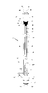
[0032] Referring to Figures 1 and 2, there is shown a ground support
apparatus 10
according to a preferred embodiment of the present invention.
[0033] The apparatus 10 comprises a first portion 12 and a second portion
14. The
first portion 12 comprises an elongated body 20 having an outer portion 17
that defines a
lumen 19. The lumen 19 extends along a longitudinal axis of the elongated body
20 and
is disposed between a first end 22 and a second end 24 of the elongated body
20.
[0034] The first portion 12 of the ground support apparatus 10 further
comprises
frictional means and, as can be seen in the Figures, the frictional means is
defined, at
least in part, by the outer portion 17 of the elongated body 20.
[0035] The outer portion 17 comprises a resilient material shaped
complementary to a
borehole into which, in use, the apparatus 10 is to be installed. The
elongated body 20
resembles or comprises a friction rock bolt configuration wherein the outer
portion 17
comprises a substantially arcuate wall 26 substantially formed about the lumen
19.
[0036] A gap 28 is formed between opposed edges 30, 32 of the arcuate wall
26. It
will be understood that the gap 28 provides for an amount of flexure of the
wall 26 such
that the edges 30,32 may be moved closer to one another during a radial
compression of
the elongated body 20. The variation in the gap 28 corresponds with a change
in an outer
CA 02966910 2017-05-05
WO 2016/065391
PCT/AU2015/000637
6
dimension of the arcuate wall 26 during fitting of the apparatus 10 to a
borehole which
has a smaller internal diameter than a free standing outer dimension of the
elongated
body 20, for example.
[0037] The resilient nature of the elongated body 20 ensures that the gap
28 is biased
toward an expanded position thereby urging the elongated body 20 into a radial
expansion after a compressive installation process and thereby provides a
source of
frictional communication between the arcuate wall 26 and an inner surface of
the
borehole.
[0038] The elongated body 20 of the preferred embodiment of the present
invention
may comprise any dimension of length and/or free standing outer diameter,
however it
will be appreciated that the dimensions of the apparatus 10 will be
substantially
complementary to a receiving rock body borehole such that the first portion 12
may be
forcefully inserted into the borehole.
[0039] During a forceful insertion, the wall 26 of the elongated body 20 is
compressed such that the opposed edges 30,32 move closer to one another
thereby
narrowing the gap 28. The resilient and tensile material of elongated body 20
acts to
provide a resultant internally generated radially expanding force acting along
the length
of the elongated body 20 and urging the elongated body 20 into an interference
fit with
the borehole. It will be understood that a force acting in an orientation
generally parallel
with the longitudinal axis upon the first portion 12 of an installed apparatus
10 will be
opposed by the frictional force generated by the radially expanding force.
[0040] It is also an advantage of the present invention that there is no
pull ring
required on the elongated body 20. Known friction rock bolts comprise a pull
ring
welded to a peripheral end of the rock bolt for limiting travel of the rock
bolt into the
borehole and for assisting in removing the rock bolt from the borehole. Known
pull rings
are welded about a circumference of the rock bolt and can be counterproductive
to the
function of the rock bolt in that they operate to resist compressive or
expansive urges
developed in the bolt.
CA 02966910 2017-05-05
WO 2016/065391
PCT/AU2015/000637
7
[0041] The second portion 14 of the apparatus 10 is arranged to at least
abut and
preferably engage the first portion 12. The second portion 14 comprises a
localised
anchor means consisting of a resilient collar 42 having a lumen 44 passing
therethrough,
the collar lumen 44 being adapted to receive a support means therethrough.
[0042] The support means preferably comprises a solid and continuous
elongated
support member 50 made from a resilient metal material having a high degree of
tensile
strength. The elongated support member 50 comprises a top end 54 and a bottom
end 52
and extends substantially through the complete elongated length of the
apparatus 10.
[0043] The elongated support member 50 is disposed inside the lumen 44 of the
resilient collar 42 and is non-releasably attached therein using a secure
fastening method.
Preferably, the elongated support member 50 is fastened inside the lumen 44
permanently by a welding process (not shown).
[0044] Alternatively, the internal surface of the lumen 44 preferably
comprises a
threaded section (not shown) that engages with a complimentary threaded
section
disposed on the external surface of the elongated support member 50 towards
its top end
54 (not shown). In this arrangement, during manufacture of the apparatus 10
the collar
42 is screwed tightly onto the elongated support member 50 with sufficient
torque such
that the collar 42 is attached to the elongated support member 50 non-
releasably.
[0045] Towards the first end 22 of the elongated body 20, there is provided
an
elongated collar 100 disposed, at least in part, inside the lumen 19 of the
elongated body
20. As most clearly shown in Figures 2 and 4, the elongated collar 100 is,
preferably,
substantially cylindrical in shape and is manufactured from a resilient
material having
high tensile strength such as, for example, steel.
[0046] An outer surface of the elongated collar 100 is substantially in
contact with an
interior surface of the outer portion 17 of the elongated body 20. The co-
efficient of
friction between the two surfaces is, however, sufficiently low such that, in
use, the
elongated collar 100 is able to travel smoothly along the longitudinal length
of the lumen
19 defined by the outer portion 17.
CA 02966910 2017-05-05
WO 2016/065391
PCT/AU2015/000637
8
[0047] The elongated collar 100 extends through to the lower end of the
apparatus 10
and substantially protrudes from its lower end.
[0048] As shown in Figure 6, the elongated collar 100 is hollow and
comprises a
lumen 115 that passes through the longitudinal length of the elongated collar
100. The
elongated support member 50 is disposed inside the lumen 115 and extends
through
towards a bottom end of the elongated collar 100.
[0049] Also, disposed towards the bottom end of the elongated collar 100,
there is
further provided a flange assembly. The flange assembly consists of a
substantially
threaded portion 110 disposed on the exterior surface of the elongated collar
100 which
also extends towards the lower end of the apparatus 10. The flange assembly,
further,
consists of a complementary nut 55 (preferably, a locking nut, as customarily
used in the
art) that threadedly engages with the threaded portion 110. The nut 55 is
preferably
dimensioned to be complementary to installation equipment, such as a jumbo rig
for
example. As shown in Figures 1 and 2 (omitted in all other Figures), the
flange
assembly, further, consists of thrust plate 62 that is disposed between the
nut 55 and a
rock face of the rock body to be supported and which substantially abuts the
rock face.
[0050] Disposed towards the top end of the elongated collar 100, there is
provided a
yielding section 70. During manufacture of the apparatus 10, the elongated
support
member 50 is guided into the lumen 115 of the hollow elongated collar 100. The
elongated collar 100 is then compressed at the yielding section 70, using a
radial press
machine or equivalent cold pressing method. This causes the elongated collar
100 to
undergo a substantial deformation and, as shown schematically in Figure 1,
causes the
radius of the lumen 115 to reduce at the yielding section 70 forming a
stricture.
[0051] The stricture that is formed increases considerably the co-efficient
of friction
between the interior wall of the lumen 115 and the surface of the elongated
support
member 50 disposed therein at the yielding section 70. This results in an
extremely
strong interference fit between the elongated support member 50 and the
elongated collar
100 at the yielding section 70. This interference fit provides that the
elongated collar 100
is not able slide along the elongated support member 50 unless a considerable
force is
applied to the support member 50 relative to the elongated collar 100.
CA 02966910 2017-05-05
WO 2016/065391
PCT/AU2015/000637
9
[0052] The flange assembly may additionally comprise a cylindrical seat 61
disposed
between the thrust plate 62 and the nut 55. As shown in Figures 1, 2, 4 and 5,
the top end
of the cylindrical seat 61 is tapered providing a substantially rounded
surface. In use,
when the nut 55 is tightened during installation of the apparatus the
cylindrical seat 61
may freely rotate about, and travel along, the threaded section 110 of the
elongated collar
100.
[0053] The cylindrical seat 61 serves to evenly distribute and spread the
load that
would otherwise be placed on the thrust plate 62 by the nut 55 thus allowing
the thrust
plate 62 to move more easily along the longitudinal axis of the apparatus 10
as the
apparatus is pre-tensioned during installation. Further, the tapering at the
top end of the
cylindrical seat 61 enables the thrust plate 62 to be secured to a rock face
effectively in
situations where the rock face surface is aligned at an angle that is not
perpendicular to
the elongate length of the elongated body 20; for example, because the
apparatus 10 has
been driven into the rock face at an angle. The rounded surface of the
cylindrical seat 61
at its tapered end ensures that a uniform, evenly distributed force is applied
to the thrust
plate 62 in these situations thereby allowing the apparatus 10 to support the
rock face
effectively.
[0054] The apparatus 10 may be fitted to a borehole using known forceful means
such
as those provided by underground installation equipment, including jumbo rigs
and/or
production drills for example. The apparatus 10 is arranged with the thrust
plate 62 fitted
over the threaded portion 110 of the elongated collar 100, followed by the
cylindrical
seat 61 and then the nut 55.
[0055] The apparatus 10 is positioned adjacent a borehole such that the
collar 42 and
the second portion 14 is inside the borehole. A force is then applied to the
apparatus 10,
preferably via the nut 55, urging the apparatus 10 into the borehole and
compressing the
friction means of the first portion 12. The apparatus 10 is urged into the
borehole until
the elongated body 20 is substantially received therein and the bottom end 52
of the
elongated support member 50 substantially protrudes from the rock face.
[0056] A pre-tensioning step is then applied to the apparatus 10 for
activating the
localised anchor means and developing a point anchor 18 between the first and
second
CA 02966910 2017-05-05
WO 2016/065391
PCT/AU2015/000637
portions 12, 14. The pre-tensioning step involves tightening the nut 55 to a
predefined
tension which causes the nut 55 to bear against the cylindrical seat 61. This,
in turn,
causes a downwards force to be applied to the elongated collar 100 which, in
turn, causes
a downwards force to be applied to the elongated support member 50 by virtue
of the
substantial friction at the yielding section 70. These forces urge the first
and second
portions 12, 14 to engage one another at the junction 57. The resilient collar
42 is drawn
into the lumen 19 simultaneously urging the outer portion 17 outwardly and
developing
the point anchor 18 at the junction 57.
[0057] The collar 42 comprises a tapered nose 45 and tail 48 and, as most
clearly
shown in Figure 3, additionally comprises a gripping section 15 having a
series of
indentations or protuberances applied to its surface by knurling or a similar
manufacturing process. The gripping section 15 provides additional friction
torque
between the collar 42 and the inner surface of the lumen 19 at a junction 57
between the
collar 42 and the elongated body 20. This additional friction torque impedes
rotation of
the collar 42 when a nut 55 is tightened when the bolt apparatus 10 is pre-
tensioned
during the installation process described above.
[0058] After the apparatus 10 has been pre-tensioned, locking means (not
shown)
may, optionally, be added to the threaded section 110 of the elongated collar
100 that is
protruding from rock face in order to lock the nut 55 in place and to stop it
from
loosening or coming free. In one preferred embodiment of the present
invention, the
locking means comprises a spring (now shown) having one or more coils that are
complementary to the threaded section 110. In use, the spring is fed onto the
lowermost
end of the elongated collar 100 and is forcefully pushed up the threaded
section 110 until
the spring abuts the nut 55. The coils of the spring occupy the space defined
by the roots
of the threaded section 110 which significantly impedes the ability of the nut
55 to
revolve around the threaded section 110, thus locking the nut 55 in place.
[0059] Once installed, mesh and spray concrete or similar means may also be
used as
known in the art.
[0060] It is to be understood that the friction means of the first portion
12
substantially restrains the apparatus 10 within the borehole and anchors the
second
CA 02966910 2017-05-05
WO 2016/065391
PCT/AU2015/000637
11
portion 14 collar 42 in position. Upon a rock body failure, creep or similar
geological
event whereby the rock face loses support and can move, a weight of the rock
face is
transferred to the thrust plate 62 and, by extension, to the cylindrical seat
61, nut 55 and
elongated collar 100.
[0061] As shown in Figure 7, the friction between the elongated collar 100
and the
elongated support member 50 at the yielding section 70 allows the elongated
collar 100
to slide in a controlled manner along the elongate length of the elongated
support
member 50 by a distance proportional to the rock face weight that has been
transferred to
the thrust plate 62. In the Figure, a rock body is shown wherein the rock face
has broken
off from the main rock body and moved by a distance D following a seismic or
other
dynamic rock event. The movement of the elongated collar 100 relative to the
elongated
support member 50 allows the apparatus 10 to yield thereby extending its
ability to
continue to support the rock face and provide a safe environment for persons
present in
the area.
[0062] Further, as the elongated collar 100 slides along the elongate
length of the
support member 50 during the yielding process, as shown in Figure 7 this, in
turn, causes
the bottom end 52 of the elongated support member 50 to move inside the lumen
115 of
the elongated collar 100 at the bottom of the apparatus 10. In effect, the
relative
movement of the elongated support member 50 inside the lumen 115 of the
elongated
collar 100 indicates that the apparatus' yielding means have been engaged.
Mining
operators may, therefore, easily determine when a rock body failure or
movement event
has taken place by inspecting the base end of rock bolts installed in the rock
area.
[0063] Further, known prior art rock bolts that feature yielding mechanisms
comprise
yielding means that are disposed substantially towards the top of the bolt.
Such bolts are,
therefore, not able to withstand and support rock bodies that have experienced
shear
fractures near to the rock face. Shearing near to the rock face causes these
bolts to fail as
their yielding means are not able to govern a relative movement between the
rock face
and the bolt's localised anchor means effectively. The shearing causes such
bolts to
twist, substantially reducing their load bearing strength, and in extreme
cases snap. In
contrast, in the present invention the yielding section 70 is disposed
substantially
towards the lower end of the apparatus 10. The yielding mechanism is,
therefore, capable
CA 02966910 2017-05-05
WO 2016/065391
PCT/AU2015/000637
12
of operating when significant forces are placed on the lower end of the
apparatus 10 by
the shearing action, thus enabling the apparatus 10 to withstand and
accommodate these
types of rock failures.
[0064] Modifications and variations as would be apparent to a skilled
addressee are
deemed to be within the scope of the present invention.